Akai Alesis LD32 User manual

SPECIFICATIONS
TECHNICAL SPECIFICATIONS
Audio Outputs: 1 TRS ¼” (aux)
2 TS ¼” (main)
1 TRS ¼” (phones)
Pads: 12 velocity sensitive (w/Dynamic Articulation™)
Sample/DAC Bit
Resolution 16 / 24
Sounds: 700+
Sounds Accessible via
Pads 12
Sounds Accessible via
MIDI 120
Polyphony 32 voice
Panning 7-position user programmable
Velocity Response 8 loudness levels via pads, 127 via MIDI
Timing Resolution 96 ppq
Time Signature Range 1-128 beats per pattern
Tempo Range 30-300 BPM
Notes/Patterns/Songs
150,000 / 200 (100 user, 100 preset) / 100
Kits 100 user, 100 preset
MIDI Prog Change
Response Kit
Sync MIDI Clock with Song Position Pointer
Footswitch
Jacks/Functions Start / Stop
Count / A / B / Fill
Microphone Input TS 1/4”
Other Features Step Editing, Stereo Samples, Reverb and Compressor / EQ effects.
Power 12 VAC External Transformer, UL and CSA Approved
6 AA batteries (not included)
SERVICE MANUAL
MODEL:
ACD1

Diagnostic Specification
For
XR-20 and Alesis LD32
Product Code: ACD1/LD32
Document Version 0.90
Last Revised: 2008/01/01

1. Memory Test
Upon startup, holding down [PLAY] should run the memory test from boot code. The
screen will indicate whether the test was successful or a failure. After this test, power
down the unit to enter diagnostics mode.
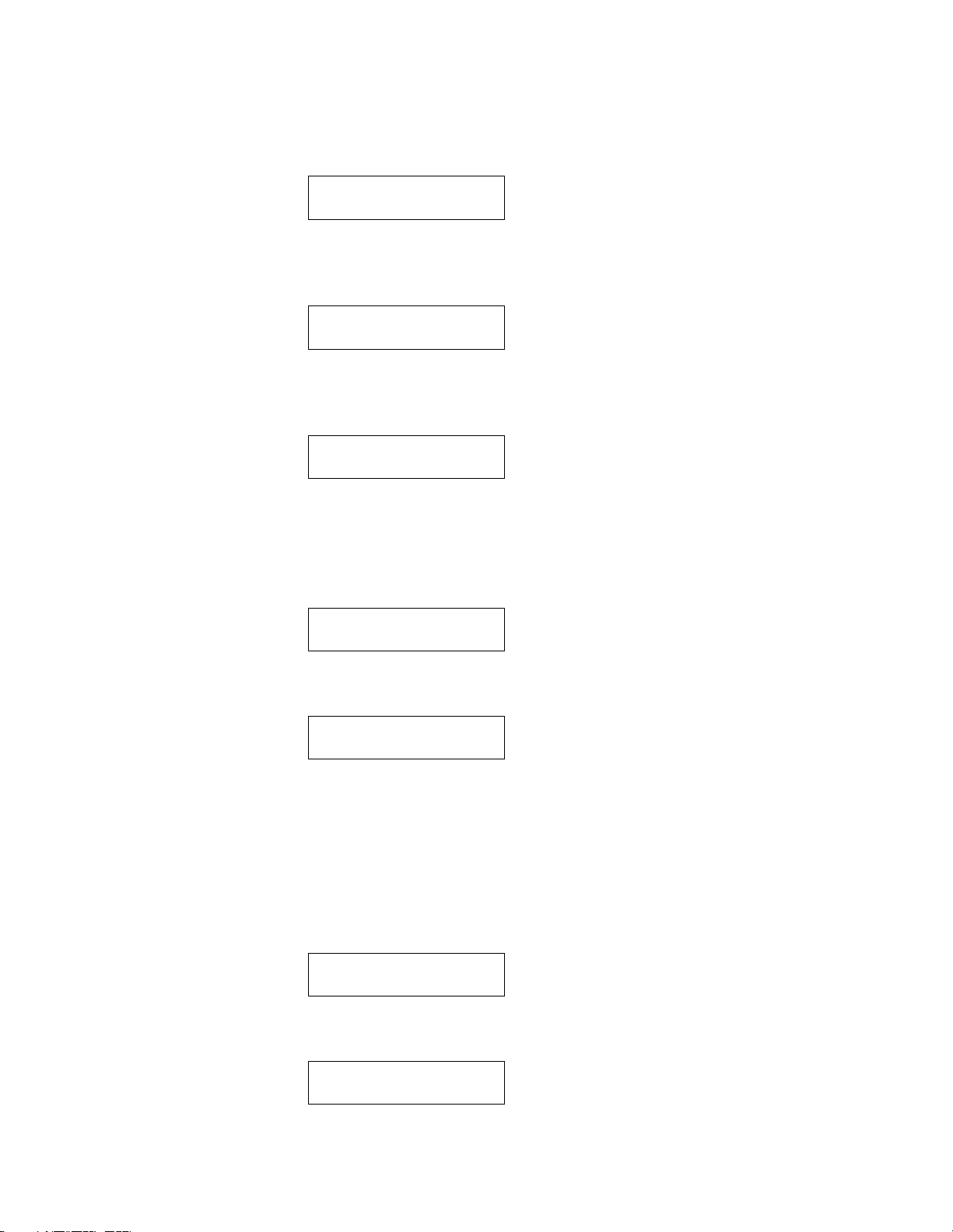
RAM Test
Wait..
And once the test is complete:
RAM Test
Passed
Or RAM Test
Failed
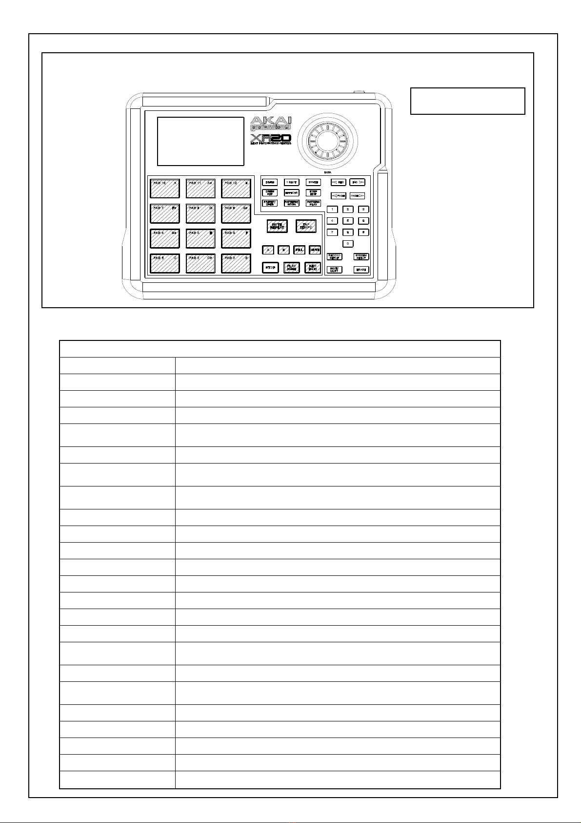
2. Entering Diagnostics Mode
Upon startup, holding down [1] and [3] should enter diagnostic mode. A restart is
required to exit diagnostic mode.
After start-up is complete the LCD should display the first test. On the test selection
page, these buttons are active.
[PAGE >] Advance to next test.
[< PAGE] Advance to the previous test
[PLAY] Execute Test.
Once within a test, the [STOP] button will exit the test to return to the test selection page.
3. Test 1: LCD Test
The LCD should show display the following:
Diags
LCD
When the test is executed, all pixels will be turned on.
4. Test 2: LED Test
The LCD should show display the following:

Diags
LED
When the test is executed, the LCD should show:
LED
All On
All LEDs shall turn on.
5. Test 3: Switch Test
The LCD should show display the following:
Diags
Switch
When the test is executed, the LCD should show:
SWITCH
The user will then press the switches one at a time. When each switch is pressed, its
name shall appear on the second line:
Drum
1Shot (“Perc” for LD32)
Synth (“Bass” for LD32)
DrmSet
Effect
StpEdt
Preset
PatSng
PatPly
NotRep (“Roll” for LD32)
TapTem
A
B
Fill
Mute
Stop
Play
Rec
Dec
Inc
<Page
Page>

1
2
3
4
5
6
7
8
9
0
RecSet
SysSet
Copy
Erase
Once all switches are pressed the LCD will display:
SWITCH
Passed
Pressing [STOP] will then bring the user to the test select page. Pressing [STOP] twice
in a row during the test will abort the test, and the LCD will display:
SWITCH
Abort
Pressing [STOP] will then bring the user to the test select page. If during the test more
than one switch is detected, the LCD should display:
SWITCH
Failed
6. Test 4: Pad Test
The LCD should show display the following:
Diags
Pads
When the test is executed, the LCD should show:
PADS

The user will then press the pads one at a time. When each pad is pressed, its number
and the input velocity shall appear on the second line, such as:
PADS
16v127
or PADS
1 v001
Once all pads are pressed the LCD will display:
PADS
Passed
Pressing [STOP] will then bring the user to the test select page. Pressing [STOP] during
the test will abort the test, and the LCD will display:
PADS
Abort
Pressing [STOP] will then bring the user to the test select page. If during the test more
than one pad is detected, the LCD should display:
PADS
Failed
7. Test 5: Footswitch Test
The LCD should show display the following:
Diags
Footsw
When the test is executed, the LCD should show:
FOOTSW
The user will then press the footswitches one at a time. When each pad is pressed, its
name shall appear on the second line, such as:
FOOTSW
Start
or FOOTSW
Count

Once all footswitches are pressed the LCD will display:
FOOTSW
Passed
Pressing [STOP] will then bring the user to the test select page. Pressing [STOP] during
the test will abort the test, and the LCD will display:
FOOTSW
Abort
Pressing [STOP] will then bring the user to the test select page. If during the test more
than one footswitch is detected at a time, the LCD should display:
FOOTSW
Failed
8. Test 6: Jog Test
The LCD should show display the following:
Diag
Jog
When the test is executed, the LCD should show:
JOG
0
As the user turns the jog wheel, the value should update on the display by increasing or
decreasing the current value. The second line should show the current integer value in
signed format.
9. Test 7: Audio Out Test
The LCD should show display the following:
Diags
Audio
When the test is executed, the LCD should show:
AUDIO
All

In this test the unit should generate a 300 Hz tone and output on all the outputs.
If [PAGE >] or [<PAGE] is pressed then the display should cycle through the following
outputs in incrementing or decrementing order based on the button (PAGE> is increase
and <PAGE will decrease).
All
MainL
MainR
AuxL
AuxR
Pressing [STOP] will stop the test and jump back to the diagnostic menu.
10. Test 8: MIDI Test
The LCD should show display the following:
Diags
MIDI
Before executing the test, a MIDI cable should be connected from the MIDI Out to the
MIDI In. When the test is executed, 16 different MIDI messages should be sent out the
MIDI output. The same MIDI input messages should be detected. If all the input
messages are the same as was sent, then the LCD should display “Passed”, otherwise the
LCD should show “Failed”.
MIDI
Passed
Or MIDI
Failed
11. Test 9: Flash Test
The LCD should show display the following:
Diags
Flash
Upon the user pressing [PLAY] the system will write/read a small reserved section of the
Flash and verify the results:

FLASH
Passed
Or FLASH
Failed
12. Test 10: Serial EEPROM Test
The LCD should show display the following:
Diags
EEPROM
Upon the user pressing [PLAY] the system will write/read a small reserved section of the
EEPROM and verify the results:
EEPROM
Passed
Or EEPROM
Failed
13. Test 11: Board ID Test
The LCD should display the following:
Diags
Board
Upon the user pressing [PLAY] the system will test that the front panel PCB and main
PCB are both stuffed for the same product
BOARD
Passed
Or BOARD
Failed

Audio Spec Test
This procedure verifies the audio specifications for mass production.


DISASSEMBLY PROCEDURES
1. DISASSEMBLE THE CABINET (Fig1)
(A) REMOVE 4 SCREWS FROM BOTTOM PANEL.
(B) REMOVE 2 PCS OF CABLE CONNECTOR FROM THE MAIN PCB.
(Fig1)

2. DISASSEMBLE THE FONCTION PCB ASS’Y. (Fig2)
(A) REMOVE THE CABLE FROM LCM
(B) REMOVE 26 SCREWS
(Fig.2)
3.DISASSEMBLE THE ENCODER PCB ASS’Y. (Fig.3)
REMOVE 3 SCREWS
(Fig.3)

4.DISASSEMBLE THE MAIN PCB ASS’Y. (Fig.4)
(A) REMOVE 1 CABLE CONNECTOR
(B) REMOVE 2 SCREWS
(Fig.4)


LEVEL
P/N DESCRIPTION QTY REF
2 TP022620T TAPE D26.5 X d20MM 4
2 PT1304702 PLATE 1
1 BA71028-130 BATTERY TERMINAL 71028-130 1 31
1 BA71209-130 BATTERY TERMINAL 71209-130 1 33
1 BA71228-130 BATTERY TERMINAL 71228-130 1 32
1 BAAR-142 RUBBER FEET 4 24
1 BAAR-8.7X5 RUBBER GASKET 2 35
1 EVA1304434 EVA 29x50x0.5mm 2 3
1 EVA1304435 EVA 70x5x0.5mm 2 4
1 EVA1304436 EVA 155x28x0.5mm 1 22
1 K46-1 CABLE TIE 1
1 LAC22AKA23 BARCODE LABEL 1 28
1 LAC67ALE59 DEMO LABEL 1 27
1 LAC67YAH261 INDICATED LABEL(GREEN) 0.5
1 LAP67YAH255 LABEL 4
1 MT133033008 BOTTOM PANEL PRINTING 1 19
2 MT1330330 BOTTOM PANEL 1
1 NP215AKA05 NAME PLATE 1 1
1 PACD1AKA01 PACK ASS'Y 1
2 AL7-51-0226 SAFETY MANUAL 1
2 AL7-91-1002 GEL SILICA 1
2 CB513S032 PARTITION 1
2 CGACD1310AKA01 GIFT BOX 1
2 CTACD1513AKA01 OUTET CARTON 0.5
2 OPACD1AKA01 OPERATION MANUAL 1
2 OPACD1AKA02 QUICK OPERATION MANUAL 1
2 PE111580BO POLYBAG 1
2 PE150350BO POLYBAG 1
2 PLACD101 POLYFOAM 1
2 PLACD102 POLYFOAM 1
2 SD30025000 SOFT SHEET 1
2 SD330308 SOFT SHEET 1.5
1 PT1304316 BATTERY HOLDER 1 15
1 PT1304317 POWER CABLE RETAINER 1 16
1 PT1330104 BATTERY COVER 1 23
1 PT151064201 JOG KNOB PRINTING 1 11
2 PT1510642 JOG KNOB 1
1 PT1510643 ALPHA KNOB 1 18
1 PT151064401 KNOB 1 20
2 AL9-15-1112 CAP KNOB 1
1 PT1530006 MAIN CABINET 1 2
1 RU1504307 FUNCTION KEYPAD 1 14
1 RU1504308 DRUM KEYPAD 1 6
1 SC0306PBBI SCREW M3*6MM PPB TAPPING 2 30
1 SC0306RIBI SCREW M3*6MM PRB 1 17
1 SC0306RICI SCREW M3*6MM PRZ 2 21
1 SC0308PBBI SCREW M38mm PPB TAPPING 4 9
1 SC0308RBNI SCREW M3x8mm PRN TAPPING 3 13
1 SC2605RBNI SCREW M2.6x5mm PRN TAPPING 26 8
1 AL9-79-0448 MAIN PCB ASS'Y 1
2 AL0-09-0074 POTENTIOMETER ROTARY 10K 25A S 1 P1
2 AL0-15-0103 RESISTOR 17 R16,24,25,59,75,76,107,110,112,116
ACD1AKA BOM

R158~164
2 AL0-16-1151 RESISTOR 1.15K(SMD)1%0805 2 R3,128
2 AL0-16-3830 RESISTOR 1 R123
2 AL0-16-8251 RESISTOR 6 R26,52,55,86,87,92
2 AL1-08-0223 ELECT 1 C99
2 AL1-51-0475 C.CAP 150P/50V 1 C98
2 AL1-55-0470 CERMAIC 47PF NPO 50V 0805 4 C31,32,63,65
2 AL1-55-0561 CAP 560PF NPO 0805 2 C76,78
2 AL1-55-0680 CERAMIC 4 C30,43,48,62
2 AL1-55-0751 CAP 750PF NPO 0805 4 C17,34,60,69
2 AL1-56-0102 CAP 1000PF NPO 100V 0805(SMD) 12 C1,4~6,11,16,18~20,22,35,50
2 AL1-70-2102 CAP 10UF TANT-A 20% 10V 3 C88,117,121
2 AL2-50-4149 DIODE IN4148 SOT-23 2 D5,6
2 AL2-51-0140 DIODE MBRS140LT3 4 D1,2,11,14
2 AL2-51-4401 TRANSISTOR 2N4401 3 Q1,2,13
2 AL2-51-4403 TRANSISTOR 2N4403 9 Q5,7,9,16~21
2 AL2-54-0138 TRANSIST0R 2 Q11,15
2 AL2-54-2114 TRANSIST0R 2SD2114K 6 Q3~4,6,8,10,12
2 AL2-61-2674 IC REG VOLTAGE LM2674M-ADJ 150 1 U9
2 AL2-62-0245 IC 1 U20
2 AL2-71-4580 IC NJM4580E 1 U17
2 AL2-72-0339 IC LM339 SOP-14 1 U3
2 AL2-74-0181 IC TLP181 1 U1
2 AL2-75-4345 IC CS4345 TSSOP-10 2 U4,10
2 AL4-00-0002 JACK 2 J3,4
2 AL4-02-0006 JACK 5 J1,2,5,7,8
2 AL4-02-0007 JACK 2 J6,9
2 AL4-14-0014 CONNECTOR 1 J14
2 AL6-02-0001 SWITCH 1 SW1
2 AL7-20-0070 BEAP 0805 SMD 42 L1,2,6~15,R14,22,89,99,118,119,122,126
R127,137~139,142~144,146~148,166~177
2 AL7-20-0071 BEAD SMD 1806 2 L5,17
2 AL7-20-0087 INDUCTOR 15UH 2.3A ±15% DIP 1 L3
2 AL7-20-1039 INDUCTOR 39UF PE-53814SNL SMD 1 L4
2 AL9-40-0431 MAIN PCB 6Layer FR-4 1.6T 198X 1 -
2 AL9-61-0183 IC FIRMWARE FLASH(ICS29GL256N) 1 U19
3 ICS29GL256N IC S29GL256N TSOP-56 1 -
2 CS103K5003X7R CAP SMD 0.01uF 10%50V 03X7R 7 C72,100,101,104,106,124,130
2 CS104K5003X7R CAP SMD 0.1uF 10%50V 03X7R 68 C2,3,8,12,13,15,26,27,33,37,49,51,52,58
C59,61,64,66,71,73,74,77,80,83,84,86,87
C90,93,95~97,102,103,105,107~109,110,111
C113~115,118~120,122,123,125~129,131,133
C134~138,140~146,168
2 CS105K1605X7R CAP SMD 1UF 10%16V 05X7R 2 C42,116
2 CS122J5005NPO CAP SMD122J50-05NPO 2 C75,79
2 CS151J5005NPO CCAP SMD 150pF/50V 5% 0805 NPO 1 C10
2 CS180J5005NPO CCAP SMD 18pF/50V 5% 0805 NPO 4 C29,46,85,94
2 CS334K5005X7R CAPACITOR 2 C36,112
2 EC10735TLE E. CAPACITOR 1 C54
2 ECS15725F Aluminum Electrolytic Capacito 2 C38,39
2 ECS22616C Aluminum Electroltic Capacitor 24 C7,14,21,23,24,25,28,40,41,44,45,47,53
C55,56,57,67,68,70,81,91,92,132,139
2 ECS68606D Aluminum Electrolytic Capacito 1 C82
2 IC74AHC174 IC 74AHC174 SOP-16 1 U14
2 IC74AUP1G32 IC 74AUP1G32 SOT23-5 1 U11
2 IC74LVC14 IC 74LVC14 SOP-14 2 U5,16
2 IC74VHC27M IC 74VHC27M SOP-14 1 U12

2 ICBF531 IC DSP ADSP-BF531 1 U21
2 ICK4S641632E SDRAM IC 1 U23
2 ICLM317 IC LM317 1.5A SOT-223 1 U22
2 ICM25PE80 IC 8Mbit , low-voltage,Page-Er 1 U15
2 ICMC34074A IC MC34074ADR2G SOIC-14 3 U6~8
2 ICMIC809SU RESET IC(2.93V) 1 U13
2 ICNJM2387 IC 1 U2
2 JKDJ-0702B-025 JACK 1 J10
2 LDLTST-C190KRKT LED 5 D7,15~18
2 PT1304702 PLATE 1 (J4)
2 RS00018J05 RES 0
5% SMD 0805 7 R46,98,108,114,121,140,151
2 RS001K08J05 RES SMD 1K 8 R15,32,36,41,44,49,56,77
2 RS020K08J05 RES SMD 20K 5% 0805 9 R28,29,33,37,38,42,57,78,94
2 RS022008J05 RES SMD 220
1 R5
2 RS024908F05 RES 249
1% SMD 0805 1 R95
2 RS043208F05 RES 432
1% SMD 0805 1 R102
2 RS047008J05 RES SMD 470
8 R23,45,64,66,82,83,84,88
2 RS04K708J05 RES SMD 4K7 7 R20,47,74,124,131,134,152
2 RS100K08J05 RES 100K (SMD) 6 R21,63,73,96,100,106
2 RS15318J05 RES 15K 5% SMD 0805 2 R117,125
2 RS18218J05 RES 1.8K SMD 1 R68
2 RS18318J05 RES 18K (SMD) 1 R43
2 RS24018J05 RESISTOR 6 R132,135,136,141,149,157
2 RS30018J05 RESISTOR 3 R133,155,156
2 RS30418F05 RES 300K(SMD)1% 1 R62
2 RS43318J05 RES 43K(SMD) 1 R109
2 RS4K1208F05 RESISTOR 4.12K 1% 0805 19 R27,50,51,53,54,60,61,69,70,71,85,90
R91,93,97,101,103,104,105
2 RS51018J05 RESISTOR 9 R7,58,111,115,129,130,150,153,154
2 RS560K08J05 RES 560K 5% SMD 0805 1 R165
2 RS62018J05 RESISTOR 62 4 R65,79~81
2 RS62318J05 CAPACITOR 1 R48
2 RS6K1908F05 RESISTOR 6.19K 1% 0805 2 R67,72
2 RS75218F05 RESISTOR 1 R4
2 RSN0470104J03 RES NETWORK 470
5% 1/10W SMD 1 R113
2 TCS107M040B CAP 100uF B-CASE LOW-ESR 1 C89
2 TE612000202 TERMINAL 2P 2.0 180° 1 J11
2 TE612000402 TERMINAL(4P)180° 1 J12
2 TE962003002 BOX HEADER STRAIGHT PITCH 2.0M 1 J15
2 TRFDS9431A TRANS FDS9431A 20V 3.5A SOIC-8 1 Q14
2 UHPH3001IG PLATE CORE 114
@100MHZ 30X1.5 1 (U21)
2 XTM08000X6F1 CRYSTAL 8MHZ HC49SMD 1 X1
1 AL9-79-0447 FUNCTION PCB ASS'Y 1
2 AL0-15-0102 RESISTOR 8 R4,6,32~36,43
2 AL0-15-0103 RESISTOR 14 R2,5,37~42,93~98
2 AL0-15-0222 RESISTOR 6 R1,27~31
2 AL1-56-0104 CERAMIC 8 C1~8
2 AL2-51-4401 TRANSISTOR 2N4401 23 Q13~19,24,25,30,31,36,37,42,43,48,49
Q54,55,60,61,66,67
2 AL2-51-4403 TRANSISTOR 2N4403 7 Q7~12,20
2 AL2-56-5592 TRANSIST0R 6 Q1~6
2 AL2-62-0541 IC 1 U2
2 AL2-64-2573 IC 74HCT573M SOIC-20 2 U1,3
2 AL7-00-0001 PIEZO 4.6KHZ 4 X1~4
2 AL9-40-0447 FUNCTION PCB 1 -
2 EC10625SM ELECTRIC CAPACITOR 2 C12,13
This manual suits for next models
2
Table of contents
Other Akai Music Equipment manuals

Akai
Akai MPC Touch User manual

Akai
Akai DPS24 User manual

Akai
Akai Professional LPK25 User manual

Akai
Akai MPD218 User manual

Akai
Akai Analog Custom shop User manual

Akai
Akai S612 User manual

Akai
Akai ME25S User manual

Akai
Akai RPM500 User manual

Akai
Akai S1100 User manual

Akai
Akai Analog Custom Shop Analog Delay User manual