Akai PDP4210EA1 User manual


PDP4210EA1
Model:
SERVICE MANUAL
Safety Precaution
Technical Specifications
Block Diagram
Circuit Diagram
Basic Operations & Circuit Description
Main IC Information
Panel Information
Spare Part List
Exploded View
If you forget your V-Chip Password
Software Upgrade
This manual is the latest at the time of printing, and does not
include the modification which may be made after the printing,
by the constant improvement of product.

Safety Precaution
PRECAUTIONS DURING
SERVICING
1. In addition to safety, other parts and
assemblies are specified for conformance with
such regulations as those applying to spurious
radiation. These must also be replaced only
with specified replacements.
Examples: RF converters, tuner units, antenna
selection switches, RF cables, noise-blocking
capacitors, noise-blocking filters, etc.
2. Use specified internal Wiring. Note especially:
1) Wires covered with PVC tubing
2) Double insulated wires
3) High voltage leads
3. Use specified insulating materials for hazardous
live parts. Note especially:
1) Insulating Tape
2) PVC tubing
3) Spacers (insulating barriers)
4) Insulating sheets for transistors
5) Plastic screws for fixing micro switches
4. When replacing AC primary side components
(transformers, power cords, noise blocking
capacitors, etc.), wrap ends of wires securely
about the terminals before soldering.
5. Make sure that wires do not contact heat
generating parts (heat sinks, oxide metal film
resistors, fusible resistors, etc.)
6. Check if replaced wires do not contact sharply
edged or pointed parts.
7. Make sure that foreign objects (screws, solder
droplets, etc.) do not remain inside the set.
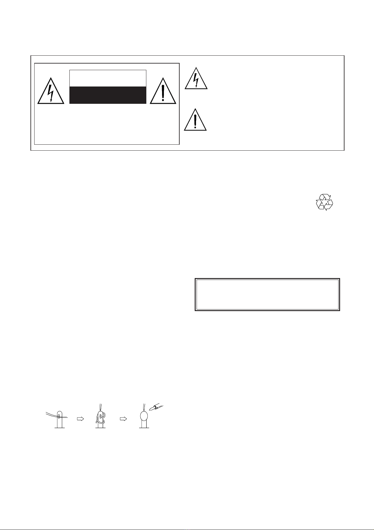
The lightning flash with arrowhead symbol,
within an equilateral triangle, is intended to
alert the user to the presence of uninsulated
“dangerous voltage” within the product’s enclo
sure that may be of sufficient magnitude to
constitute a risk of electric shock to persons.
The exclamation point within an equilateral
triangle is intended to alert the user to the
presence of important operating and
maintenance (servicing) instructions in the
literature accompanying the appliance.
CAUTION: TO REDUCE THE RISK OF
ELECTRIC SHOCK, DO NOT REMOVE COVER
(OR BACK). NO USER-SERVICEABLE PARTS
INSIDE. REFER SERVICING TO QUALIFIED
SERVICE PERSONNEL ONLY.
CAUTION
RISK OF ELECTRIC SHOCK
DO NOT OPEN
MAKE YOUR CONTRIBUTION
TO PROTECT THE
ENVIRONMENT
Used batteries with the ISO symbol
for recycling as well as small accumulators
(rechargeable batteries), mini-batteries (cells) and
starter batteries should not be thrown into the
garbage can.
Please leave them at an appropriate depot.
WARNING:
Before servicing this TV receiver, read the
SAFETY INSTRUCTION and PRODUCT
SAFETY NOTICE.
SAFETY INSTRUCTION
The service should not be attempted by anyone
unfamiliar with the necessary instructions on this
apparatus. The following are the necessary
instructions to be observed before servicing.
1. An isolation transformer should be connected in
the power line between the receiver and the
AC line when a service is performed on the
primary of the converter transformer of the set.
2. Comply with all caution and safety related
provided on the back of the cabinet, inside the
cabinet, on the chassis or picture tube.
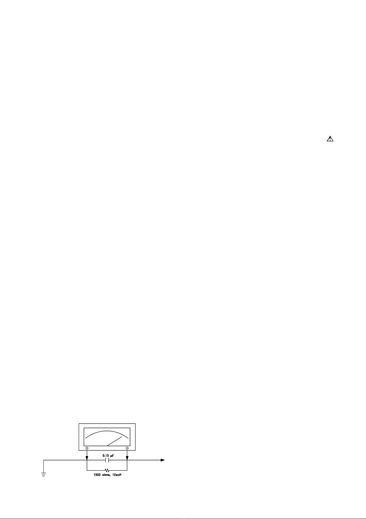
3. To avoid a shock hazard, always discharge the
picture tube's anode to the chassis ground
before removing the anode cap.
4. Completely discharge the high potential voltage
of the picture tube before handling. The picture
tube is a vacuum and if broken, the glass will
explode.

PRODUCT SAFETY NOTICE
Many electrical and mechanical parts in this
apparatus have special safety-related
characteristics.
These characteristics are offer passed
unnoticed by visual spection and the protection
afforded by them cannot necessarily be obtained
by using replacement components rates for a
higher voltage, wattage, etc.
The replacement parts which have these
special safety characteristics are identified by
marks on the schematic diagram and on the parts
list.
Before replacing any of these components,
read the parts list in this manual carefully. The
use of substitute replacement parts which do not
have the same safety characteristics as specified
in the parts list may create shock, fire, or other
hazards.
9. Must be sure that the ground wire of the AC
inlet is connected with the ground of the
apparatus properly.
5. When replacing a MAIN PCB in the cabinet,
always be certain that all protective are
installed properly such as control knobs,
adjustment covers or shields, barriers, isolation
resistor networks etc.
6. When servicing is required, observe the original
lead dressing. Extra precaution should be given
to assure correct lead dressing in the high
voltage area.
7. Keep wires away from high voltage or high
tempera ture components.
8. Before returning the set to the customer,
always perform an AC leakage current check
on the exposed metallic parts of the cabinet,
such as antennas, terminals, screwheads,metal
overlay, control shafts, etc., to be sure the set
is safe to operate without danger of electrical
shock. Plug the AC line cord directly to the
AC outlet (do not use a line isolation
transformer during this check). Use an AC
voltmeter having 5K ohms volt sensitivity or
more in the following manner.
Connect a 1.5K ohm 10 watt resistor paralleled
by a 0.15µF AC type capacitor, between a
good earth ground (water pipe, conductor etc.,)
and the exposed metallic parts, one at a time.
Measure the AC voltage across the combination
of the 1.5K ohm resistor and 0.15 uF
capacitor. Reverse the AC plug at the AC
outlet and repeat the AC voltage measurements
for each exposed metallic part.
The measured voltage must not exceed 0.3V
RMS.
This corresponds to 0.5mA AC. Any value
exceeding this limit constitutes a potential
shock hazard and must be corrected
immediately.
The resistance measurement should be done
between accessible exposed metal parts and
power cord plug prongs with the power switch
"ON". The resistance should be more than
6M ohms.
Good earth ground
such as the water
pipe, conductor,
etc.
Place this probe
on each exposed
metallic part
AC VOLTMETER
AC Leakage Current Check

1. Standard Test Conditions
All tests shall be performed under the following conditions, unless otherwise specified.
1.1 Ambient light : 150ux (When measuring IB, the ambient luminance
≦0.1Cd/m2)
1.2 Viewing distance : 50cm in front of PDP
1.3 Warm up time : 30 minutes
1.4 PDP Panel facing : no restricted
1.5 Measuring Equipment : Minolta CA 210 photometer
1.6 Magnetic field : no restricted
1.7 Control settings : Brightness, Contrast, Tint, Color set at Center(50)
1.8 Power input : 120Vac,60Hz
1.9 Ambient temperature : 20°C ± 5°C (68°F ± 9°F)
1.10 Display mode : 31.5KHz/60Hz (Resolution 852 x 480)
1.11 Other conditions :
1.11.1 With image sticking protection of PDP module, the luminance will descend
by time on a same still screen and rapidly go down in 5 minutes. When
measuring the color tracking and luminance of a same still screen, be sure
to accomplish the measurement in one minute to ensure its accuracy.
1.11.2 Due to the structure of PDP, the extra-high-bright same screen should not
hold over 5 minutes for fear of branding on the panel.
Technical Specifications PDP4210EA1

ELECTRICAL CHARACTERISTICS
2. Power Input
2.1 Voltage : 120VAC
2.2 Input Current : 3.5A
2.3 Maximum Inrush Current : <30 A (FOR AC 120V ONLY)
Test condition : Measured when switched off for at least 20 mins
2.4 Frequency : 60Hz(±3Hz)
2.5 Power Consumption : ≤330W
Test condition : full white display with maximum brightness and
contrast
2.6 Power Factor : Meets IEC1000-3-2
2.7 Withstanding voltage : 1.5kVac or 2.2kVdc for 1 sec
3. Display
3.1 Screen Size : 42” Plasma display
3.2 Aspect Ratio : 16:9
3.3 Pixel Resolution : 852x480
3.4 Peak Brightness : 1500 cd/m² (Panel module without filter)
3.5 Contrast Ratio (Dark room) : 10000:1 (Panel module without filter)
3.6 Viewing Angle : Over 160°
3.7 OSD language : English,Spaish, French
4. Signal
4.1 AV & Graphic input
4.1.1 TV standard : NTSC/ATSC
4.1.2 TV Tuning system : 181CH (for NTSC), 2~69CH (for ATSC)
4.1.3 CATV : 125CH (for NTSC)
4.1.4 Composite signal : AV
4.1.5 Y,C Signal : S-Video
4.1.6 omponent signal :YPbPr HDTV compatible
4.1.7 Graphic I/P : D-Sub 15 pin detachable cable
4.1.8 HDMI : HDMI
4.1.9PnP compatibility :DDC 1.0
4.1.10 I/P frequency : fH: 31.5kHz to 60kHz/fV: 56.25Hz to 75Hz (640x480
recommended)
Tchnical Specifications PDP4210EA1

4.2 Audio input
Audio I/P(L/Rx5) : 1 for DVI / D-Sub
2 for YPbPr
1 for S-Video
1 for AV
4.3 Audio output
Audio O/P(L/Rx1) : Monitor out(L/R)
SPDIF : Optical x 1 (only for ATSC)
5. Environment
5.1 Operating environment
5.1.1 Temperature : 5º to 33°C
5.1.2 Relative humidity: 20% to 85%(non-condensing)
5.2 Storage and Transport
5.2.1 Temperature : -20°C to 60°C(-4º to 140°F)
5.2.2 Relative humidity: 5% to 95%
6. Panel Characteristics
6.1 Type : LG V7
6.2 Size : 42”, 1005mm(width)x597mm(height)x61mm(depth)±1
mm)
6.3 Aspect ratio : 16:9
6.4 Viewing angle : Over 160°
6.5 Resolution : 852x480
6.6 Weight : 14.7kg ±0.5 kg (Net 1EA)
6.7 Color : 1073.7 million colors by combination of 10 bits R,G,B digital
6.8 Contrast : Average 100:1 (In a bright room with 100Lux at center)
Typical 10000:1 (In a dark room 1/100 White Window
pattern at center).
6.9 Peak brightness : Typical 1500cd/㎡(1/100 White Window)
6.10 Color Coordinate Uniformity : Contrast; Brightness and Color control
at normal setting
Test Pattern : Full white pattern
Average of point A,B,C,D and E +/- 0.01
Technical Specifications PDP4210EA1

6.11 Color temperature : Contrast at center (50); Brightness center (50);
Colortemperature set at Middle
x=0.285±0.02
y=0.293±0.02
6.12 Cell Defect Specifications
Subject to Panel supplier specification as appends.
7. Front Panel Control Button
7.1 CH Up / Down Button : Press the key to changing the channel up or down.
When selecting the item on OSD menu.
Volume Up/ Down Button : Press the key to increase the volume up or down.
When selecting the adjusting item on OSD menu
increase or decrease the data-bar.
Menu Button : Press the key to display or exit the menu.
It has the function of Enter in the Menu.
Input Button : Press the key to select the input signals source.
7.2 Stand by Button : Switch on main power, or switch off to enter power
Saving modes.
7.3 Main Power Switch : Turn on or off the unit.
8. OSD Function
Full on screen display
9. Agency Approvals
Safety UL60950
Emissions FCC class B
10. Reliability
10.1 MTBF:20,000 hours (Use moving picture signal at 25°C ambient)
11. Accessories: User Manual x 1, Remote Control x 1, Stand x 1, Power Cord x 1, Battery x2.
Technical Specifications PDP4210EA1

Technical Specifications PDP4210EA1
12. Remote Control
Standby ( ): Press to turn on and off.
Mute ( ): Press to mute the sound.
Press again to restore the sound.
0~9 Number Buttons: Press 0~9 to
select a channel, and used to input the
password; the channel changes
after
2 seconds.
EPG (Electronic Program Guide):
Press to display EPG mode.
Press again to exit EPG mode.
Input: Press to select the signal
source, such as DTV, TV, AV, S-Video,
YPbPr 1, YPbPr 2, VGA, or HDMI.
DTV: Press to choose DTV directly.
Dot: Press number buttons with it to
select the channels directly in DTV.
VOL +/-: Press to adjust the volume.
CH +/- : Press to select the channel
forward or backward.
MTS: Press repeatedly to cycle through
the Multi-channel TV sound (MTS)
options: Mono, Stereo and SAP
(Second Audio Program).
◄,►,▲,▼, Enter: Press ◄,►,▲,
▼ to move the on-screen cursor. To
select an item, press Enter to confirm.
Exit: Press this button to exit.
Menu: Press to enter into the on-screen
setup menu, press again to exit.
V-Chip: Press to select the child
protect mode.
CCD: Press to select the Closed
Caption mode.
Freeze: Press to freeze the picture,
press again to restore the picture.
Display: Press to display the channel information and it disappear after 3 seconds.
Favorite: Press repeatedly to cycle through the favorite channel list.
Add/Erase: Press to add or delete favorite or dislike channels.
S. Mode: Press repeatedly to select the sound mode:
Normal
, News, Cinema, Concert and
User.
PIC Size: Press repeatedly to cycle through the picture size that best
corresponds your
viewing requirements:
Full, 4:3 and Panoramic.
(Continued on next page)

Technical Specifications PDP4210EA1
Note: Press CH +/- button on the remote control can turn on TV set from standby mode.
If the volume is too loud from the other external devices (such as, DVD, VCR, etc.), we
suggest that you press VOL +/- button to adjust the volume of PDP into appropriate.
If the volume of the other external devices (such as, DVD, VCR, etc.) and PDP are too
loud, the audio quality will be influenced.
Insertion of Batteries:
- Turn the remote control upside down, press and slide off the battery cover.
- Insert two 1.5V (AAA) batteries into the compartment, take care to observe the and
markings indicated inside.
- Replace the cover and slide in reverse until the lock snaps.
P. Mode: Press repeatedly to cycle
through the picture mode: Cinema,
Normal
, Vivid, Hi-Bright and User.
System:
Press repeatedly to cycle
through the system options: AUTO,
NTSC 3.58 and PAL. (Only for AV
or S-Video)
Recall: Press to return to previous
channel.
Sleep: Press repeatedly until it
displays the time in minutes (15 Min,
30 Min, 60 Min, 90 Min, 120 Min and,
Off) that you want the TV to remain
on before shutting off. To cancel sleep
time, press Sleep button repeatedly
until sleep Off appears.
Red: Press this button to access the
red item or page.
Blue: Press this button to access the
blue item or page.
Green: Press this button to access
the green item or page.
Yellow: Press this button to access
the yellow item or page.

Technical Specifications PDP4210EA1
13. Support the Signal Mode
A. VGA Mode
- When the signal received by the Display exceeds the allowed range, a warning message shall
appear on the screen.
- You can confirm the input signal format from the on-screen.
Resolution
Horizontal
Frequency
(KHz)
Vertical
Frequency
(Hz)
640 x 480 31.50 60.00
37.86 72.81
800 x 600
35.16 56.25
37.90 60.32
46.90 75.00
48.08 72.19
1024 x 768 48.40 60.00
Resolution
Horizontal
Frequency
(KHz)
Vertical
Frequency
(Hz)
480i 15.734 59.94
480p(720x480) 31.468 59.94
720p(1280x720) 45.00 60.00
1080i(1920x1080) 33.75 60.00
Resolution
Horizontal
Frequency
(KHz)
Vertical
Frequency
(Hz)
480p 31.468 59.94
720p 45.00 60.00
1080i 33.75 60.00
B. YPbPr Mode
C. HDMI Mode

PHYSICAL CHARACTERISTICS
14. Power Cord
Length : 1.8m nominal
Type : optional
15. Cabinet
15.1 Color :“Black” colour as defined by colour plaque reference number
15.2 Weight
Net weight : 33.6kg(with stand) /31.4kg(without stand)
Gross weight : 41.0 kg
15.3 Dimensions(w/o stand)
Width : 1050mm
Height : 657 mm
Depth : 99.5 mm
Technical Specifications PDP4210EA1

BLOCK DIAGRAM
Control Signal
LVDS Input
Color Plasma Display Panel
852 X 480 pixels
Address Driver
Scan Driver
Common sustain driver
Display data, Driver timing
Memory
Controller
Driver
Timing
Controller
Input
Interface
Controller Vcc(+5V)
Va(60V~65V)
Vs(180V~190V)
(I2C)
☞Applied Voltage level is specified at the time when Full-White pattern is displayed on the panel.

A
A
B
B
C
C
D
D
E
E
4 4
3 3
2 2
1 1
Title
Size Document Number Rev
Date: Sheet of
ZhongShan KAWA Electronic Inc.
Drawn:
Checked:
AKAI_MT8202_MT5351_V1.0
1
C
12Friday, March 17, 2006
MT5351 Block
KAWA Confidential
<Designer>
<Checker>
Title
Size Document Number Rev
Date: Sheet of
ZhongShan KAWA Electronic Inc.
Drawn:
Checked:
AKAI_MT8202_MT5351_V1.0
1
C
12Friday, March 17, 2006
MT5351 Block
KAWA Confidential
<Designer>
<Checker>
Title
Size Document Number Rev
Date: Sheet of
ZhongShan KAWA Electronic Inc.
Drawn:
Checked:
AKAI_MT8202_MT5351_V1.0
1
C
12Friday, March 17, 2006
MT5351 Block
KAWA Confidential
<Designer>
<Checker>
ATSC SYSTEM
MT5111
DTV Front_end
(U11)
MT5351
DTV Back_end
(U14)
32Mb
Flash
(U17)
Video[0...23]
data audio signal
TO MT8202
UART0(Communication
with MT8202)
control signal
UART2(Download)
DDR
256Mb
(U15)
DDR
256Mb
(U18)
LP2996
(U19)
1.25V
2.5V
Data[0..31]
Address[0..11]
X6965D
SAW Filter
(U9)
TD1336
Tuner
(U8)
Coaxial
Power Supply
1.8V
1.25V
3.3V
2.5V
UPC3218
AGC Amplifier
(U10)
I2C
2nd_IF+&2nd_IF-
Differential
Data Stream
5v
SPDIF
TS[0..7]
Contral
Signal
I2C
EEPROM
24C16
(U13)

A
A
B
B
C
C
D
D
E
E
4 4
3 3
2 2
1 1
Title
Size Document Number Rev
Date: Sheet of
ZhongShan KAWA Electronic Inc.
Drawn:
Checked:
AKAI_MT8202_MT5351_V1.0
1
D
22Friday, March 17, 2006
MT8202 Block
KAWA Confidential
<Designer>
<Checker>
Title
Size Document Number Rev
Date: Sheet of
ZhongShan KAWA Electronic Inc.
Drawn:
Checked:
AKAI_MT8202_MT5351_V1.0
1
D
22Friday, March 17, 2006
MT8202 Block
KAWA Confidential
<Designer>
<Checker>
Title
Size Document Number Rev
Date: Sheet of
ZhongShan KAWA Electronic Inc.
Drawn:
Checked:
AKAI_MT8202_MT5351_V1.0
1
D
22Friday, March 17, 2006
MT8202 Block
KAWA Confidential
<Designer>
<Checker>
AUDIO Bypass
WM8776
(U41)
AV1 Audio
YPbPr1 Audio in
YPbPr2 Audio in
S_Video Audio
HEF4052
(U52)
MT8202
U12
Video[0...23]
data audio signal
control signal
From MT5351
J24
74LVC244A
U30-U33
(BUFFER)
UART0
(Communication with MT5351)
VGA
EEPROM
24C02
(U53)
VGA_I2C
MAX3232
(U54)
Level shift
UART
(TXD/RXD)
MT8202 Download
VGA Signal Input
3.3V
5V
AV Audio inAV2 Audio
VGA Audio in
Din
Dout
CLK
EEPROM
24C16
(U2)
MT8293
HDMI Receiver
(U25)
Video/audio signal
control signal
EEPROM
24C02
(U51)
I2C(MT8202I2C)
5V UPA672T
(U34)
Level Shift
HDMI_I2C
MT8253
I2C
NJM4558
OPA
(U60)
HDMI
Connector
P1
TMDS0~3
HDMIPLUG_PWR
I2C(MT8202I2C)
R2S15103
(U57) TO
Speaker
Flash
16Mb
(U17)
DDR
128Mb
(U18)
DDR
128Mb
(U19)
5V
3.3V
LP2996
(U20)
1.25V
2.5V
Data[0..31]
Address[0..11]
HDCP_I2C
EEPROM
24C04
(U50)
3.3V
CVBS3(CVBS0 is from tuner)
YPbPr×2
S_VIDEO
Video Bypass
PDP
Connector
TO PDPLVDS Data
PDP
Control Signal
Audio Bypass
3.3v
2.5v
NJM4558
OPA
(U46)
1.8v

Circuit Diagram
- Power supply board of PDP Module, 1H273W
- Main (Video) board
- Audio/Tuner board
- ATSC board
- Keypad board
- Remote control receiver board
- External L/R Speakers board
- Remote control board


5
5
4
4
3
3
2
2
1
1
D D
C C
B B
A A
9. WM8776 & VIDEO BYPASS
2. LDO
SYSTEM EEPROM
12. LVDS OUT
13. BACK LIGHT / KEYPAD
Rev DateP#History
AKAI_MT8202_27US_LVDS_V0.0
5. DDR MEMORY & FLASH
New 2005/11/22
H : WP DISABLE
L : WP ENABLE
8202UP3_1 HIGH :POWER OFF
8202UP3_1 LOW :POWER ON
3. MT8202E PBGA388
1. INDEX / POWER / RESET / EEPROM
4. MT8202 DECOUPLING
6. MT5351 INTERFACE
8. DAUGHTER BOARD IN
11 . VGA & PC AUDIO IN
POWER ON RESET# CIRCUIT
POWER DOWN RESET# CIRCUIT
10. AUDIO / VIDEO IN CIRCUIT
FROM POWER BOARD
MT8202E (PBGA388) LCDTV BOARD 4 LAYERS FOR AKAI
AKAI_MT8202_27US_HDMI_LVDS_V0.0
17.AUDIO Amplifier
14. TUNER IN
15. AV IN
16. AUDIO IN
7. HDMI MT8293
ADD HDMI / VIDEO /AUDIO CONNECTOR INPUT IN
HI = > POWER ON
LO = > POWER OFF
INDEX / POWER / RESET / EEPROM
1
C
117Monday, February 27, 2006
AKAI_MT8202_27US_LVDS_V0.0
KAWA Confidential
<Designer>
<Checker>
Title
Size Document Number Rev
Date: Sheet of
ZhongShan KAWA Electronic Inc.
Drawn:
Checked:
8202UP3_1
SCL
SDA
URST#
GPIO4
8202UP3_1
URST#
GPIO4
+5V/+6V
9VV
SYSROMWP
SCL
SDA
9V
9VV
VS_ON
RELAY_ON
LVDSVDD
9VV
VCC
12V
12V
12V
9VV
RELAY_ON
VS_ON
12V +12V
+12V
+5V/+6V VCC
SYS_PWR
URST#
9VV
VCC +5V/+6V
GPIO14
GPIO14
GPIO19
GPIO19
GPIO2
GPIO2
9VV
9VV 9V
9V
9V
LVDSVDD
8202UP3_1 3
SDA 9,14
SCL 9,14
URST# 3
GPIO4 3
9V 7,9,14
12V 12,13
RELAY_ON 12
VS_ON 12
GPIO14 3,13
GPIO19 3,13
GPIO2 3,12
LVDSGND 2,3,4
5VSB
SB33A
5VSB
5VSB
SB33B
SB33B
5VSB
SB33B
SB33B
+5V/+6V
+12V
+12V
VCC
5VSB
SB33B
5VSB
J23
DIP7/W/H/P2.54
1
2
3
4
5
6
7
D26
1N4001/SMD
R635
10k/NC
R57 1K
Q19
2N3904
SOT23/SMD
1
3 2
C4
1uF
FB39 FB/NC
R675 100
R776
10k
C153
1000pF/NC
CB188
0.1uF
R337 10
R52
NC
D1
1N4148/SMD
R8
47k
R339
10k
R14 10K
FB40 FB/NC
R7770/NC C681
1uF/NC
R645
10K
C154
1000pF/NC
R37
NC
D23
1N4001/SMD
=
DIODE SMD/NC
+
CE144
220uF/16v
R744
470 U61 KA278RA05/NC TO-220F-4L
4
1 2
3
VDIS
IN OUT
GND
CB5
0.1uF
R22 NC
U2
EEPROM 24C16
SOP8/SMD
1
2
3
4 5
6
7
8
NC
NC
NC
GND SDA
SCL
WP
VCC
C176
20pF
CB2
0.1uF/NC
+
CE110
47uF/16v
FB42 FB/NC
R324
10K
CB3
0.1uF
CB6
0.1uF/NC
H3 HOLE/GND
2
3
4
5
9
8
7
6
1
2
3
4
5
9
8
7
6
1
+
CE4
10uF/25v
U62
IRF7316
SOIC8/SMD
1
2
3
45
6
7
8S1
G1
S2
G2D2
D2
D1
D1
R340
4.7k
CB15
0.1uF
Q20
2N3904
1
3 2
+
CE3
100uF/16v/NC
FB2 FB/NC
R13
20K
R7780
R10
4.7K
R9
1k/NC
D24
1N4001/SMD
R77922K
R. ANGLE
J7
DIP10/WH/P2.54/R
1
2
3
4
5
6
7
8
9
10
J6
11x1
DIP11/P2.54
1
2
3
4
5
6
7
8
9
10
11
FB43 FB/NC
R674 100
+
CE1
220uF/16v
R639
0
R676 10K/NC
R637
10K
D2
1N4148
CB207
0.1uF
FB3 FB/NC
CB20
0.1uF
+
CE6
100uF/16v.NC
H1 HOLE/GND
2
3
4
5
9
8
7
6
1
2
3
4
5
9
8
7
6
1
CB1
0.1uF
Q44
2N3904
SOT23/SMD/NC
1
3 2
H2 HOLE/GND
2
3
4
5
9
8
7
6
1
2
3
4
5
9
8
7
6
1
D25
1N4001/SMD
+
CE145
470uF/16v
C175
20pF
R338
0
R638
10K
R11
100k/NC
Q4
2N3904
SOT23/SMD
1
3 2
R15
10K/NC
Q21
2N3904
SOT23/SMD
1
3 2
CB4
0.1uF/NC
U1
LM809
SOT-23/SMD/NC
1
2
3
GND
RESET
VCC
R775
22k
+
CE12
100uF/10v
C100UF10V/D5H11
Q45
2N3904
1
3 2
+
CE2
100uF/16v
H4 HOLE/GND
2
3
4
5
9
8
7
6
1
2
3
4
5
9
8
7
6
1

5
5
4
4
3
3
2
2
1
1
D D
C C
B B
A A
Power ON alive source
1.25x(1+180/300)=1.99V
1.25x(1+62/110)=1.95V
change 2/16
LDO
1
C
217Monday, February 27, 2006
AKAI_MT8202_27US_LVDS_V0.0
KAWA Confidential
<Designer>
<Checker>
Title
Size Document Number Rev
Date: Sheet of
ZhongShan KAWA Electronic Inc.
Drawn:
Checked:
ADCV18A
VFE_GND1
VFE_GND
LVDS_GND
VFE_GND1
ASB33A
ASB18A
AV18A
AV33A
AV33A
SB18ASB18SB33A
LVDS_GND
DV18A
LVDS_GND
LVDS_GND
LVDS_GND
LVDS_GND
DACVDD
LVDS_GND
SB18
VFE_GND
SB33
VFE_GND1 3,4,8,11
VFE_GND 3,4,8,11
LVDS_GND 3,4,12
ADCV33A
DV33B
ASB33A
SB18ASB33A
ASB18A
AV18A
AV33A
DV18A
DV33A
VCC
SB33
SB33B
5VSB
ADCV18A
DACVDD
VCC
L10 FB
CB18
0.1uF
+
CE79
100uF/16v
CB9
0.1uF
+
CE81
100uF/16v
CB22
0.1uF
CB187
0.1uF
+
CE11
100uF/16v
U4
AZ1117/adj
SOT223/SMD
1
23
ADJ/GND
OUTIN
U7
AZ1117-3.3V
SOT223/SMD
1
23
ADJ/GND
OUTIN
L6 FB
U37
AZ1117/adj
SOT223/SMD
1
23
ADJ/GND
OUTIN
CB24
0.1uF
+
CE10
100uF/16v
CB10
0.1uF
+
CE15
220uF/16v
L50 FB
R773
110 1%
CB206
0.1uF
L51 FB
+
CE108
220uF/16v
CB17
0.1uF
L47 FB
+
CE109
220uF/16v
CB189
0.1uF
CB23
0.1uF
CB8
0.1uF
+
CE13
100uF/16v
R325
300 1%
R774
62 1%
CB202
0.1uF
CB7
0.1uF
+
CE80
100uF/16v
+
CE20
220uF/16v
L43 FB/1206
+
CE78
100uF/16v
+
CE9
100uF/16v
+
CE8
100uF/16v
+
CE18
220uF/16v
+
CE14
100uF/16v
L4 FB
L7 FB
+
CE103
470uF/16v
U8
AZ1117-1.8V
SOT223/SMD
1
23
ADJ/GND
OUTIN
+
CE17
220uF/16v
L5 FB
L42
FB
CB21
0.1uF
R326
180 1%
L8 FB
+
CE7
100uF/16v
L48 FB
+
CE21
220uF/16v
+
CE82
100uF/16v
L49 FB/NC
U11
AZ1117-3.3V
SOT223/SMD
1
23
ADJ/GND
OUTIN
L46 FB
+
CE104
470uF/16v
U3
AZ1117-3.3V
SOT223/SMD
1
23
ADJ/GND
OUTIN
Table of contents
Other Akai TV manuals

Akai
Akai PDP5006H User manual

Akai
Akai 29CT24FS User manual

Akai
Akai 21CTF66BC User manual

Akai
Akai PT50DL14 User manual

Akai
Akai ATF-505 User manual

Akai
Akai PS-4210X User manual

Akai
Akai CT-S21MTD-E3 User manual

Akai
Akai 21CTS92FS User manual

Akai
Akai CT-S14MTD-E3 User manual

Akai
Akai LEA-19H03P User manual