manuals.online logo
Brands
  1. Home
  2. •
  3. Brands
  4. •
  5. AKCP
  6. •
  7. Accessories
  8. •
  9. AKCP Airflow User manual

AKCP Airflow User manual

Airflow Sensor User
Manual
On / Off Type & Percentage
Firmware versions SP+ 1.0.4997 - SP76 - SEC405s
Copyright © 2019, AKCP Co., Ltd.
Airflow Sensor User Manual
- 2 -
Introduction
There are two versions of AKCP Airflow sensors. The percentage type and the On and Off type.
The percentage type was replaced by the On and Off type around August of 2011. The old
percentage type Airflow sensors are obsolete and not supported any longer.
The first type, the On / Off type will be covered first. These sensors are not supported on
sensorProbe units that use the ATmega128 flash memory and use the 459i firmware version.
They are supported on our sensorProbe+ (SP2+ & SPX+) & our securityProbe base units (see
our support section firmware upgrade page for more information on identifying your unit type).
On / Off Type Airflow Sensor
AKCP is only shipping the On/Off type of Airflow sensor.
Configuring the Airflow sensor on your sensorProbe+ unit
a) Plug the sensor into one of the RJ45 ports on the rear, or front panel of the unit. The Airflow
sensors can be extended using CAT5/CAT6 UTP straight through cables. The maximum run
length from the AKCP base units RJ-45 sensor port to the sensor is 100 feet or 30 meters.
Important Note: When extending the sensor you cannot use patch panels, RJ-45 couplers or
running these extension cables near or on any equipment that will emit EMI (electrical magnetic
interference).
b) Now point your browser to the IP address of the unit (default, 192.168.0.100). Next you need
to login as the administrator using your administrator password (default is “public”). You will then
be taken to the main page.
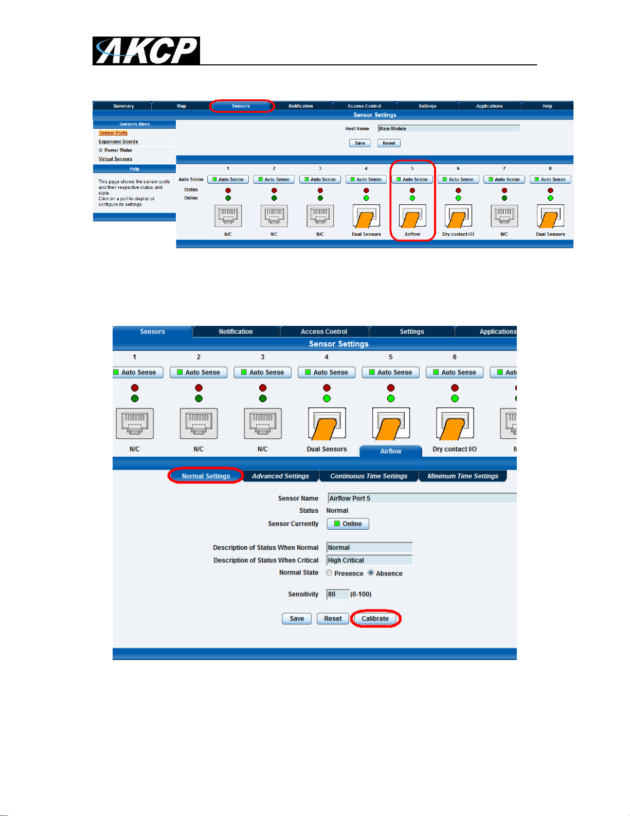
c) From the summary page you need to select the sensors link. The layout of the next page will
vary depending on your unit so please refer to your AKCP base unit’s product manual on our
website (“All Manuals” link).
Now we will cover the settings that are specific to your base unit.
sensorProb2+ & sensorProbeX+ (SP2+ & SPX+) Base Units
Airflow Sensor User Manual
- 3 -
After connecting the sensor it will be auto sensed as the Airflow Sensor as shown above.
Now you can re-name your Airflow sensor, adjust the rearm and sensitivity settings and
change the Normal State.
You can change the Normal state to be in the normal state when the airflow is present or
not present. This is quite convenient in the event you required to be alerted if airflow is
present that is not desired, for example, an air sealed clean lab where Airflow should only
be flowing out of the room and not in. However, most applications are for cooling fans or
air conditioning.
Sensitivity –You may want to adjust the Airflow sensors sensitivity. This will allow you to
allow the sensor to be more sensitive to the presence of air. 100 is most sensitive to
Airflow and 0 is least sensitive. Do keep in mind this is not a high priced precision Airflow
sensor. Also, to be as accurate as possible at sensing and not sensing the Airflow, the
sensor must be placed so the Airflows over the top of the sensor.
Airflow Sensor User Manual
- 4 -
Important Note: When changing the sensitivity setting you must re-calibrate the Airflow
sensor again running both the 100% followed by a 0% calibration. The calibration steps
will be covered next.
Calibration –The Airflow sensors MUST be calibrated before they will function properly.
To begin the calibration of the sensor, first ensure the sensor is still online, then click on
the “Calibrate” button.
Next select the air state. 100% when the Airflow is present and 0% when the Airflow is
not present.
Important Note: Be sure to WAIT for 2 minutes BEFORE clicking on the Calibrate
button. Also keep in mind it takes 30-45 seconds to register the state change of the
sensor. These details also apply to our sensorProbe and securityProbe base units below.
Polling the On/Off Type Airflow sensor via SNMP.
The Airflow sensor is not a switch type sensor, as it is measuring and reporting a level of
airflow from 0 to 100, but it has only 2 status’s.
This sensor uses the sensorProbeHumidityTable OID. Kindly refer to our latest MIB file
located on our support website and also OID manual for more details on this.
continued
Airflow Sensor User Manual
- 5 -
Advanced Tab –The Rearm setting affects the sensors status changes. This is uses to
avoid a sensor status to toggle many times when the value fluctuates around the
threshold value. So, if you are not seeing the changes in the status as expected, then you
should adjust the Rearm to 0.
Important Note: These settings including the Advanced and Continous Time settings are
covered in the SP+ product manuals, so please refer to these that are on our website.
Configuring the airflow sensor on your sensorProbe unit
a) Plug the sensor into one of the RJ45 ports on the rear panel of the unit.
b) Now point your browser to the IP address of the unit (default, 192.168.0.100). Next you need
to login as the administrator using your administrator password (default is “public”). You will then
be taken to the summary page.
c) From the summary page you need to select the sensors tab. The layout of the next page will
vary depending on your unit so please refer to your units manual.
Now we will cover the settings that are specific to your sensor.
sensorProbe Base Units
Airflow Sensor User Manual
- 6 -
After connecting the sensor it will be auto sensed as the Airflow Sensor. After clicking on
the Sensors tab you would then click on the sensor settings link as shown in the screen
shot above.
In the settings tab you first make sure the sensor is online, and then you can re-name
your Airflow sensor, adjust the rearm and sensitivity settings and change the Normal
State.
You can change the Normal state to be in the normal state when the airflow is present or
not present. This is quite convenient in the event you required to be alerted if airflow is
present that is not desired, for example, an air sealed clean lab where Airflow should only
be flowing out of the room and not in. However, most applications are for cooling fans or
air conditioning.
After clicking on Calibrate tab, you are able to calibrate the airflow sensor. The airflow
sensor should be calibrated only if the sensor does not seem to be detecting airflow
properly.
To calibrate the sensor follow the instructions on the screen and click on the calibrate b
utton as shown in the screen shot above.
Airflow Sensor User Manual
- 7 -
After clicking on the Calibrate button, a reminder will be displayed as shown above, then
you would click the OK button to begin the calibration of the airflow sensor.
For the Relay Control and Siren Control please see the Dry Contact, Sensor Controlled
Relay or the Siren / Strobe user manuals for information on these options.
Clicking on the Status Filters tab we can see now that you can enable or disable the email and traps for this,
enable or disable the email or trap when the status returns to a Normal State and also set the Continuous Time
settings to elimate false warnings, set the Minimum time between each Email or Trap and also set the Day and
Time filter as shown in the screen shot above.
Airflow Sensor User Manual
- 8 -
securityProbe Base Units
After connecting the sensor to the RJ-45 sensor port and logging into the unit as the
Admin and navigating to the Sensors page the airflow sensor will be auto sensed and
displayed as shown in the screen shot above.
After clicking on the Airflow sensor the Normal Settings will be displayed where you are
able to then rename the sensor, rename the Status and change the Normal State to the
Presence or Absence of airflow.
The sensitivity can be set to a specific number in the event the airflow is a lot or very low.
Airflow Sensor User Manual
- 9 -
To calibrate the Airflow Sensor, click in the Calibrate button as shown above.
After clicking on Calibrate button, you are able to calibrate the airflow sensor. The airflow
sensor should be calibrated only if the sensor does not seem to be detecting airflow
properly.
To calibrate the sensor follow the instructions on the screen and click on the calibrate
button as shown in the screen shot above.
Airflow Sensor User Manual
- 10 -
After clicking on the Calibrate button, a reminder will be displayed as shown above, then
you would click the OK button to begin the calibration of the airflow sensor.
Percentage Reading Type Airflow Sensor
The way the percentage type Airflow sensor works is there are two thermistors, one internal and
one external. A thermistor changes resistance based on air temperature. The internal thermistor
is the reference point and the external thermistor changes when the airflow is blown across the
top of the sensor, the difference is this raw output reading. Then the raw output reading is
calculated into the percentage of airflow.
Important Note: Again, as noted in the beginning section, this percentage type Airflow sensor is
obsolete and not supported any longer on the sensorProbe (firmware 476), securityProbe (405s)
and our sensorProbe+ units (SP2+ & SPX+).
The calculations are as follows;
rawAnalog 550 = 1.375 Volt = 100%
rawAnalog 150 = 0.375 Volt = 0%
The sensor will be much more accurate if it is positioned so the Airflows across the top of the
sensor and this is not a precision sensor. It is basically designed to sense the presence and
non-presence of airflow.
The airflow sensor is really designed to sense the presence of air, not to measure the amount of
airflow. The best application is to place it near the air source but if you want a reading of less than
100% then you need to place it further away but again it is not designed to be an anemometer. It
is best used to send an alert in the case of a fan, or in your case, AC failure.
Airflow Sensor User Manual
- 11 -
If you need a more precision sensor then these are much more expensive but can be integrated
into the AKCP base units. Please contact support for more information.
The Airflow Sensor is a device that registers airflow in areas where consistent flow is needed; for
example, in cabinets and racks where the consistent operation of a fan is critical to the
operational safety of electronic equipment.
The Airflow sensor is placed in the air stream, where the user can monitor the status and the
amount of flowing air. In addition to an on/off indication, it also graphs the analog values over a
period of time. Although this is not a precision airspeed measurement device, it can be used, for
example, to indicate if a fan slows down the user will be given an indication of the change over
time. This may happen if the fan is close to failure or the air filter is clogged.
The recognized OID for the Airflow sensor on RJ45#1 is .1.3.6.1.4.1.3854.1.2.2.1.17.1.3.0
Features:
oOn/Off alarm signal of airflow
oAirflow data graphically displayed over time
oAccurate, cost effective flow sensing
o2 LEDs indicate the status of Airflow and that the sensor is securely plugged into the
unit
oElectronics are mounted in a small plastic case
oPower source: powered by the unit. No additional power needed.
oThe unit auto detects the presence of the airflow sensor .
oFull Autosense including disconnect alarm
Specifications:
oData graphically displayed via a web page
oData collection possible via any SNMP based network management system
oMeasurement rate: one reading each second, data logging once per minute
oCommunication cable: RJ-45 jack to the unit
oSensor type: Thermistor
oTrap information: Status, Sensor number, Sensor description, Airflow (%) (ONLY on
the older type airflow sensor)
oMaximum CAT5/6 Cable Extension Run Length: 60 meters or 200 feet.
Configuring the airflow sensor
a) Plug the sensor into one of the RJ45 ports on the rear panel of the unit.
Airflow Sensor User Manual
- 12 -
b) Now point your browser to the IP address of the unit (default, 192.168.0.100). Next you need
to login as the administrator using your administrator password (default is “public”). You will then
be taken to the summary page.
c) From the summary page you need to select the sensors tab. The layout of the next page will
vary depending on your unit so please refer to your units manual.
Now we will cover the settings that are specific to your sensor.
Current Reading: The percentage of airflow is displayed in this field. This is a read-only field. It is
an integer SNMP OID field. This value can be polled via SNMP and the data can be used to
graph the air-flow. The values range is from 0 to 100 %.
Status: If the sensor is offline, the status shows “No Status”. If the sensor is online, the status
will be formed by comparing the readings to the low thresholds. If at any time communications
with the Airflow Sensor are lost, the status of the Airflow Sensor is changed to “sensorError”.
Can I extend the airflow sensor, if yes, how do I do that and how far can I extend it?
Yes, you can extend the airflow sensor using standard CAT5 LAN cable. The total run length of
this sensor is 30 meters or roughly 98 feet.
This concludes the Airflow sensor user manual.
Please contact s[email protected] if you have any further technical questions or problems setting up your
modem or your alerts.
Thanks for Choosing AKCess Pro!

Other AKCP Accessories manuals

AKCP IO-digital8 User manual

AKCP

AKCP IO-digital8 User manual

AKCP ropeWater User manual

AKCP

AKCP ropeWater User manual

AKCP UFLS User manual

AKCP

AKCP UFLS User manual

AKCP Thermal Map User manual

AKCP

AKCP Thermal Map User manual

AKCP SP2+ User manual

AKCP

AKCP SP2+ User manual

Popular Accessories manuals by other brands

Honeywell Home PROSiXPANIC installation instructions

Honeywell Home

Honeywell Home PROSiXPANIC installation instructions

Techlink RECHARGE 2600 instructions

Techlink

Techlink RECHARGE 2600 instructions

Campbell CS511 product manual

Campbell

Campbell CS511 product manual

Mobicool T35 instruction manual

Mobicool

Mobicool T35 instruction manual

Steren TIM-250 instruction manual

Steren

Steren TIM-250 instruction manual

Chillout QUANTUM PRO installation guide

Chillout

Chillout QUANTUM PRO installation guide

Hedstrom MO8681 user guide

Hedstrom

Hedstrom MO8681 user guide

Axis T8341 user manual

Axis

Axis T8341 user manual

Flex-a-Lite 32050 installation instructions

Flex-a-Lite

Flex-a-Lite 32050 installation instructions

S+S Regeltechnik HYGRASGARD RPFF Operating Instructions, Mounting & Installation

S+S Regeltechnik

S+S Regeltechnik HYGRASGARD RPFF Operating Instructions, Mounting & Installation

Sygonix 2572668 operating instructions

Sygonix

Sygonix 2572668 operating instructions

Dometic 8270000.401 Series installation instructions

Dometic

Dometic 8270000.401 Series installation instructions

Lorex B463AJ Series quick start guide

Lorex

Lorex B463AJ Series quick start guide

Wellcare Oasis manual

Wellcare

Wellcare Oasis manual

Ningbo Fiercer Leopard Electrical Appliance Co., Ltd. S-1801 manual

Ningbo Fiercer Leopard Electrical Appliance Co., Ltd.

Ningbo Fiercer Leopard Electrical Appliance Co., Ltd. S-1801 manual

La Crosse Technology TX24U instruction manual

La Crosse Technology

La Crosse Technology TX24U instruction manual

Cooper Controls Greengate OAWC-DT-120W installation instructions

Cooper Controls

Cooper Controls Greengate OAWC-DT-120W installation instructions

Four-Faith F8L10GW user manual

Four-Faith

Four-Faith F8L10GW user manual

manuals.online logo
manuals.online logoBrands
  • About & Mission
  • Contact us
  • Privacy Policy
  • Terms and Conditions

Copyright 2025 Manuals.Online. All Rights Reserved.