Akern BIA 101 BIVA PRO User manual

Instruction manual

INSTRUCTION MANUAL
Rev. 0 dated 09/2020 Pages 2to 67
Read this instruction manual carefully and keep it on hand for future consultation.
The information in this document is subject to revision without notice.
Visit the website for the latest versions.
All rights reserved. No part of this document may be photocopied, reproduced or translated into other languages without prior
written consent.
Document code: Man_BIVA_PRO REV 0 | 09-2020
Revision status: rev. 0 of 18/09/2020

INSTRUCTION MANUAL
Rev. 0 dated 09/2020 Pages 3to 67
CONTENTS
CONTENTS ...........................................................................................................................................3
CHAPTER 1: GENERAL AND SAFETY INFORMATION ................................................................................5
1.1 INTENDED USE ...................................................................................................................................................................5
1.2 INTENDED USER STAFF ......................................................................................................................................................5
1.3 INTENDED PLACE OF USE ..................................................................................................................................................5
1.4 MISUSE...............................................................................................................................................................................5
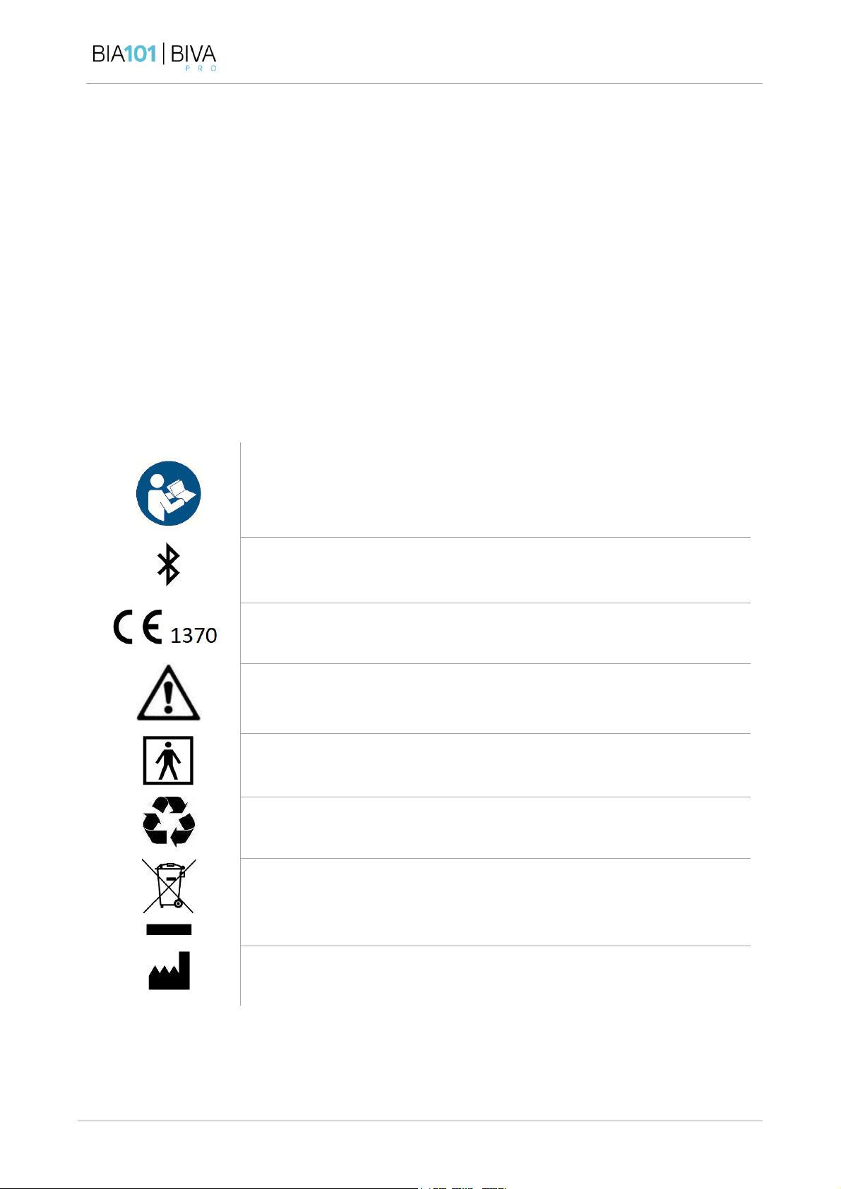
1.5 DEFINITIONS AND SYMBOLS...............................................................................................................................................6
1.6 ELECTROMAGNETIC COMPATIBILITY....................................................................................................................................6
1.7 SAFETY WARNINGS ............................................................................................................................................................7
1.8 NORMATIVE REFERENCES...................................................................................................................................................9
1.9 CLASSIFICATION OF THE DEVICE ........................................................................................................................................9
1.10 CLINICAL VALIDATION..................................................................................................................................................... 10
1.11 APPLIED PARTS...............................................................................................................................................................10
CHAPTER 2: DEVICE AND ACCESSORIES................................................................................................ 11
2.1 DESCRIPTION OF THE DEVICE.......................................................................................................................................... 11
2.2 DESCRIPTION OF ACCESSORIES....................................................................................................................................... 13
CHAPTER 3: USE OF THE DEVICE ..........................................................................................................20
3.1 PRELIMINARY PROCEDURES .............................................................................................................................................20
3.2 SWITCHING ON AND OFF................................................................................................................................................ 20
3.3 AUTOTEST .......................................................................................................................................................................20
3.4 HOME.............................................................................................................................................................................. 21
3.5 CLINIC &FIELD WORKING MODES ............................................................................................................................... 22
3.6 TOTAL BODY |BIA ANALYSIS .......................................................................................................................................23
3.7 REGIONAL ANALYSES |BIA...........................................................................................................................................30
3.8 SETTINGS MENU ..............................................................................................................................................................36
CHAPTER 4: STANDARD OPERATING PROCEDURE (SOP).......................................................................43
4.1 PRELIMINARY INFORMATION............................................................................................................................................ 43
4.2 POSITIONING THE PATIENT ..............................................................................................................................................43
4.3 POSITIONING THE ELECTRODES .......................................................................................................................................44
4.4 PRECAUTIONS AND WARNINGS .......................................................................................................................................47
CHAPTER 5: DEVICE MAINTENANCE..................................................................................................... 49
5.1 POWER SUPPLY............................................................................................................................................................... 49
5.2 CHARGING THE BATTERIES .............................................................................................................................................. 49
5.4 CALIBRATION AND TESTING.............................................................................................................................................50

INSTRUCTION MANUAL
Rev. 0 dated 09/2020 Pages 4to 67
5.4 CLEANING........................................................................................................................................................................ 53
5.5 STORAGE.........................................................................................................................................................................53
5.6 MAINTENANCE AND REPAIR ............................................................................................................................................ 54
5.7 DISPOSAL........................................................................................................................................................................54
CHAPTER 6: TROUBLESHOOTING FOR COMMON PROBLEMS................................................................55
6.1 BIA101 BIVA PRO SYSTEM ALERTS ........................................................................................................................... 55
6.2 IF MEASUREMENTS ARE INACCURATE OR UNINTELLIGIBLE ................................................................................................56
6.3 IF THE DEVICE WILL NOT SWITCH ON ...............................................................................................................................57
6.4 IF THE DEVICE DOES NOT DISPLAY RESULTS DURING MEASUREMENT............................................................................... 57
6.5 IF DATA TRANSFER IS UNSUCCESSFUL.............................................................................................................................. 57
CHAPTER 7: TECHNICAL SUPPORT AND SERVICE...................................................................................58
7.1 WARRANTY TERMS AND CONDITIONS ............................................................................................................................. 58
7.2 TECHNICAL SUPPORT SERVICE CONTACTS ......................................................................................................................58
7.3 REPORTING INCIDENTS OR NEAR MISSES ........................................................................................................................59
CHAPTER 8: OPERATING PRINCIPLES ...................................................................................................60
8.1 THEORETICAL BASES OF BIOIMPEDANCE ANALYSIS........................................................................................................60
8.2 BLOCK DIAGRAM OF OPERATION OF THE BIA101 BIVA PRODEVICE........................................................................ 61
CHAPTER 9: TECHNICAL SPECIFICATIONS .............................................................................................63
CHAPTER 10: DECLARATION OF CONFORMITY .....................................................................................64
CHAPTER 11: CONTENTS CHECKLIST ....................................................................................................65
11.1 BIA101 BIVA PRO DEVICE CHECKLIST ........................................................................................................................65
11.2 REGIONAL KIT CHECKLIST ...............................................................................................................................................66

INSTRUCTION MANUAL
Rev. 0 dated 09/2020 Pages 5to 67
CHAPTER 1: GENERAL AND SAFETY INFORMATION
1.1 INTENDED USE
The BIA101 BIVA PRO medical device was developed for real-time measurement of the electrical properties
of tissue (Resistance, Reactance and Phase Angle), used to evaluate body composition and to monitor non-
vital physiological parameters, such as hydration and nutritional status.
1.2 INTENDED USER STAFF
The use of the BIA101 BIVA PRO is intrinsically safe and non-invasive. The device can be used without
restrictions by any adult who has read the instruction manual with care.
Blind users are unable to use the device unaided.
Data obtained using BIA101 BIVA PRO may only be interpreted for therapeutic, clinical or diagnostic purposes
by suitably qualified health professionals.
Akern S.r.l. (hereinafter “Akern”) declares that the device, used as described in this manual and within the
limits set out in sections 1.7 Safety Warningsand 0 Precautions and Warnings, has been designed and
manufactured to have no effect on the patient's clinical condition and to ensure the safety of the patient,
user or any third parties.
1.3 INTENDED PLACE OF USE
Akern considers any location which complies with the environmental operating conditions specified in
CHAPTER 9: TECHNICAL SPECIFICATIONS as an intended place of use.
1.4 MISUSE
"Misuse" is any condition of use not appropriately covered by the intended use, fields of application or
operating conditions.
Any research or application protocols must comply with a preset procedure agreed with the manufacture,
which conforms to the relevant regulations.
The user must refer to the instruction manual to ensure correct use.

INSTRUCTION MANUAL
Rev. 0 dated 09/2020 Pages 6to 67
1.5 DEFINITIONS AND SYMBOLS
1.5.1 Definitions
Rz (Ohm): Electrical resistance. Defines a conductor’s opposition to the flow of an alternating electric current.
Value in Ohms.
Xc (Ohm): Capacitive Reactance. Defines the opposition of a capacitor to the flow of an alternating electric
current. Value in Ohms.
PhA (°): Phase Angle. Defines the ratio between resistance and reactance, which depends on tissues’ cellular
and electric concentration. Value in degrees.
1.5.2 Symbols
Symbol referring to the manual
Icon of Bluetooth, used for wireless communication between the BIA101 BIVA
PRO and the IT device
Marking indicating conformity to medical device Directive 93/42/EEC, as
amended
Symbol indicating a warning
Symbol indicating the subject’s protection class against direct and indirect
electrical contact: type BF applied part
Symbol recommending the recycling of polluting components
Symbol indicating controlled disposal of the product at the end of its life cycle
(in compliance with the WEEE directive)
Production site symbol
1.6 ELECTROMAGNETIC COMPATIBILITY
The device has passed electromagnetic compatibility testing in accordance with the relevant standard, IEC

INSTRUCTION MANUAL
Rev. 0 dated 09/2020 Pages 7to 67
60601-1-2, as required by directive 93/42/EEC as amended.
1.7 SAFETY WARNINGS
This section describes the precautionary measures recommended to restrict the risks due to
use of the device. Please familiarise yourself with this information to ensure the safety of
procedures when using this device, in order to minimise the risk related to its use.
Failure to comply with warnings and/or instructions may damage the device and/or its
components or be dangerous for the user.
BIA101 BIVA PRO complies with IEC 60601-1 concerning the general requirements for the electrical safety
of medical devices. A risk management procedure in accordance with EN ISO 14971 has been implemented
by the manufacturer and was approved at the time of certification. The device has also undergone the
required electromagnetic compatibility, electrostatic immunity and radio emission tests and complies with
IEC 60601-1-2. Contact the manufacturer if you wish to receive the certification documentation.
BIA101 BIVA PRO is designed for use in conjunction with other medical and/or electronic equipment
belonging to the same certification class.
Do not use the device in the presence of flammable gases, anaesthetic gases and any gaseous mixture
containing oxygen or flammable substances.
A potential risk may be caused by the injection of a 7-12 volt direct current into the human body. However,
the probability of this event is negligible because the electrode/skin contact has a high capacitive
component and the skin offers very high impedance to direct current. The use of a power distribution unit
with IEC 60601-1 certification for charging the battery further reduces the residual risk.
The use of insulated alligator clips eliminates the risk of the electrical grounding of the patient, a possibility
that may arise in the extremely unlikely eventuality of accidental disconnection of the clip. However, we
recommend that you take care to avoid accidental clip detachment. Before starting a test, verify that the
patient is suitably insulated. Besides being exposed to risks, “grounded” patients cause unreliable
measurements.
The sensor circuit board is disabled using charging of the device, and performance of a test during charging
is therefore impossible. The residual risk is therefore largely theoretical.

INSTRUCTION MANUAL
Rev. 0 dated 09/2020 Pages 8to 67
Comply with the recommendations and warnings in the manual and the messages
displayed on the device.
•Do not use the device close to water and do not pour water onto it.
oThe IPX0 protection class does not protect against penetration by liquids and the device might be
irreversibly damaged, without service or warranty cover.
•Do not place the device on unstable surfaces or trolleys.
oThe device may fall and be seriously damaged.
•To ensure operation of the device throughout its life-cycle, avoid exposure to temperatures above
45°C and therefore do not place it near radiators or in containers lacking adequate ventilation.
•During storage, relative humidity in the environment must not exceed 90% without condensation.
•Never apply any weight to the battery charger cable, the patient cable, the measuring electrodes or
the device itself.
•Do not place the device in an obstructing position when it is being charged.
•Do not plug any object into the multipole sockets of the battery charger and/or patient cables.
•Only use the accessories provided with the device.
•Do not try to repair the device: it does not contain any parts which can be repaired by unskilled staff.
Maintenance and repair must only be performed by qualified technical personnel. Tampering by
unauthorised staff causes expiry of the warranty and the certification, and could damage the device
beyond repair and put the user and the patient being analysed at risk.
•The device must only be charged using the power distribution unit supplied.
•Do not charge the device if:
othe battery charger power cord shows signs of damage;
othe device does not work properly although operating instructions have been followed correctly;
othe device has been dropped and/or the container is damaged;
othe device shows clear signs of malfunction that may require technical servicing.
•Do not replace batteries without contacting Akern or an authorized dealer. Lithium batteries have a
high explosion risk if not correctly recharged.
Remark: To replace the battery contact the Technical Support Service or Authorised Dealer

INSTRUCTION MANUAL
Rev. 0 dated 09/2020 Pages 9to 67
Important! The lithium-ion battery may explode if handled incorrectly. Do not remove it or
throw it away. Lithium-ion batteries must be disposed of in compliance with statutory
legislation. Ref. Italian Legislative Decree no. 188 of 20 November 2008, as amended by
Legislative Decree no. 21 of 11 February 2011.
Important! Use only BIATRODES or BIVATRODES electrodes, as per manufacturer’s
indications. The use of different electrodes may interfere with measurements and is defined
as an UNACCEPTABLE risk. The user is completely responsible for any use of different
electrodes.
1.8 NORMATIVE REFERENCES
This Manual was prepared in compliance with Annexes I –VI –VII of Directive 93/42/EEC, as amended.
1.8.1 Standards applied (in their most recent editions):
-Quality management systems EN ISO 13485 and EN ISO 9001
-Medical electrical equipment - Electrical safety IEC 60601-1
-Medical electrical equipment - Electromagnetic compatibility IEC 60601-1-2
-Radio frequency ETSI EN 300328 V1.8.1 / ETSI EN 301489-1; ETSI EN 301489-17
-IEC 60601-1-6 Usability
-EN 62366 Application of usability engineering to medical devices
-EN ISO 14971 Risk analysis and management
-Directive 2001/65/EC RoHS 2
-IEC 62304: Software for medical devices
-EN ISO 15223-1: Symbols for use in the labelling of medical devices
1.9 CLASSIFICATION OF THE DEVICE
BIA101 BIVA PRO is classified as a class IIa medical device (annex IX, rule 9, points 3.1, 3.2, Directive
93/42/EEC, as amended).

INSTRUCTION MANUAL
Rev. 0 dated 09/2020 Pages 10 to 67
1.10 CLINICAL VALIDATION
All clinical validation documents for the device are contained in the Clinical Evaluation Report (CER),
available for consultation by the competent authorities and for audit by Notified Bodies.
1.11 APPLIED PARTS
Akern defines the BIATRODES / BIVATRODES electrode as the only type BF applied part in direct contact
with the subject.

INSTRUCTION MANUAL
Rev. 0 dated 09/2020 Pages 11 to 67
CHAPTER 2: DEVICE AND ACCESSORIES
2.1 DESCRIPTION OF THE DEVICE
Figure 1: BIA101 BIVA PRO front panel
The BIA101 BIVA PRO has a 5” touchscreen display.
To ensure correct touchscreen operation, remember to try not to scratch it, and not to use pens,
pencils or other objects with sharp tips.
2.1.1 Connection Panel
The connection panel parts are as follows (Figure 2):
1. On / Off Button
2. AUXILIARY BIA CABLE connector for Regional Patient Cable or Regional Tester (for BIA101 BIVA
PRO devices enabled for Regional Tests)
3. BIA CABLE - CHARGE Connector for Total Body Patient Cable, Battery Charger or Total Body Tester.
4. USB connector

INSTRUCTION MANUAL
Rev. 0 dated 09/2020 Pages 12 to 67
Figure 2: BIA101 BIVA PRO connection panel
Remark: To connect a tester or a patient cable correctly, point the connector in the
direction shown in the diagram below, then fit the connector into the panel, pressing gently
until it clicks into place.
To disconnect the cable/tester from the panel, simply pull the connector towards you. Do
not attempt to unscrew the connector by turning it while it is connected.

INSTRUCTION MANUAL
Rev. 0 dated 09/2020 Pages 13 to 67
2.2 DESCRIPTION OF ACCESSORIES
The device is supplied complete with the following accessories:
•BIATRODES™ / BIVATRODES™ electrodes
•Total Body four-pole cable / Total Body BIVATRODES cable
•Regional four-pole cable / Regional BIVATRODES cable
•Battery charging power distribution unit
•Mini-USB cable
•Tester for checking Total Body / Regional calibration
2.2.1 Electrodes
The BIA101 BIVA PRO device can be used with the following types of electrodes.
BIATRODES™
BIATRODES™ single-use electrodes, class I medical
device, compliant with Directive 93/42/EEC as
amended.
The electrodes are compliant with ISO 10993 (non-
cytotoxic, non-irritant and non-sensitising).
BIVATRODES™
BIATRODES™ and BIVATRODES™ electrodes can be used only for bioimpedance analyses and are defined as
a BF Applied Part.
Figure 4: BIVATRODES™ single-use electrodes
BIVATRODES™ pre-spaced single-use electrodes,
class I medical device, compliant with Directive
93/42/EEC as amended.
The electrodes are compliant with ISO 10993 (non-
cytotoxic, non-irritant and non-sensitising).
Figure 3: BIATRODES™ single-use electrodes

INSTRUCTION MANUAL
Rev. 0 dated 09/2020 Pages 14 to 67
All devices produced by Akern are tested and calibrated with relation to the physical specifications of these
two types of electrodes, which provide the user with a stable, accurate measurement.
The quality and technical characteristics of the contact electrode are of critical importance for correct reading
of the bioimpedance values and to ensure the device retains its performance characteristics, as defined in
the risk analysis.
The use of unsuitable electrodes, not certified for bioimpedance measurement, may interfere
with the device's essential performance characteristics, generating incorrect measurements
with poor repeatability; in the worst cases it may lead to incorrect interpretation of the data.
2.2.2 Patient Cables
The patient cables described below are supplied, for use depending on the type of electrodes used for the
analysis (BIATRODES™ or BIVATRODES™).
TOTAL BODY ANALYSIS
REGIONAL ANALYSIS
BIATRODES™ electrodes
Total Body four-pole cable
Regional four-pole cable
BIVATRODES™ electrodes
Total Body BIVATRODES cable
Regional BIVATRODES cable
The patient cables associated with the BIA101 BIVA PRO device have a high level of screening, mitigating
electromagnetic interferences from the outside and also auto-induced disturbances.
However, when in use cables should be completely extended, with no loops or spirals that could
induce an auto-inductive effect and interfere with the measurement.
To avoid damaging the cable, do not twist or bend it at its ends.

INSTRUCTION MANUAL
Rev. 0 dated 09/2020 Pages 15 to 67
Total Body four-pole cable
Figure 5: Total Body four-pole cable
Four-pole patient cable for Total Body analyses using BIATRODES™ electrodes.
The cable is fitted with 4 insulated red and black alligator clips, for connection to the electrodes.
For bioimpedance measurement, the patient cable must be connected to the device via the connector
marked BIA CABLE / CHARGE (Figure 2).
Remark: The Total Body four-pole cable can be recognised by the connector colour:
blue for the Total Body cable and grey for the Regional cable. The two colours are
also used on the connection panel, to enable the user to connect each cable to the
device correctly.
Regional four-pole cable (for BIA101 BIVA PRO devices enabled for Regional analyses)
Figure 6: Regional four-pole cable
Regional four-pole patient cable, for use together with the Total Body cable for Regional analyses using
Blue splitter: HAND electrode terminals
Grey splitter: FOOT electrode terminals
Blue splitter: HAND electrode terminals
Grey splitter: FOOT electrode terminals
Blue connector
Grey connector

INSTRUCTION MANUAL
Rev. 0 dated 09/2020 Pages 16 to 67
BIATRODES™ electrodes.
The cable is fitted with 4 insulated red and black alligator clips, for connection to the electrodes.
For bioimpedance measurement, the patient cable must be connected to the device via the connector
marked AUXILIARY BIA CABLE (Figure 2).
Remark: The Regional four-pole cable can be recognised by the connector colour:
grey for the Regional cable and blue for the Total Body cable. The two colours are
also used on the connection panel, to enable the user to connect each cable to the
device correctly.
BIA 101 BIVA PRO is also compatible with dedicated BIVATRODES™ patient cables.
Total Body BIVATRODES cable
Figure 7: Total Body BIVATRODES cable
BIVATRODES cable for Total Body analyses using BIVATRODES™ electrodes.
The cable is fitted with 2 insulated blue and grey alligator clips, for connection to the hand and foot electrodes
respectively (Figure 7).
For bioimpedance measurement, the patient cable must be connected to the device via the connector
marked BIA CABLE / CHARGE (Figure 2).
Blue alligator clip: HAND
electrodes
Grey alligator clip : FOOT
electrodes
Blue connector

INSTRUCTION MANUAL
Rev. 0 dated 09/2020 Pages 17 to 67
Remark: The Total Body BIVATRODES cable can be recognised by the connector
colour: blue for the Total Body cable and grey for the Regional one. The two colours
are also used on the connection panel, to enable the user to connect each cable to
the device correctly.
Regional BIVATRODES cable (for BIA101 BIVA PRO devices enabled for Regional analyses)
Figure 8: Regional BIVATRODES cable
BIVATRODES cable for Regional analyses using BIVATRODES™ electrodes.
The cable is fitted with 2 insulated blue and grey alligator clips, for connection to the hand and foot electrodes
respectively (Figure 8).
For bioimpedance measurement, the patient cable must be connected to the device via the connector
marked AUXILIARY BIA CABLE (Figure 2).
Remark: The Regional BIVATRODES cable can be recognised by the connector
colour: grey for the Regional and blue for the Total Body cable. The two colours
are also used on the connection panel, to enable the user to connect each cable
to the device correctly.
Blue alligator clip: HAND
electrodes
Grey connector
Grey alligator clip : FOOT
electrodes

INSTRUCTION MANUAL
Rev. 0 dated 09/2020 Pages 18 to 67
2.2.3 Battery charger power distribution unit
Figure 9: Battery charger
Certified medical power distribution unit.
The battery charger output is a controlled
12 Vdc signal. The permissible input is from
100 to 240 Vac.
For instructions on charging the device, see
point 5.2 Charging the Batteries.
2.2.4
USB cable
Figure 10: Mini-USB cable for data transfer
The BIA101 BIVA PRO device has a Mini-USB
cable for transferring data to the
BODYGRAM™ DASHBOARD program (§3.8.2
Importing the database to BODYGRAM™
DESKTOP via USB ).
2.2.5
Bluetooth accessory for PC
Figure 11: Bluetooth module
Bluetooth module for use only if the PC
available does not have one (Installing the
Bluetooth module
)

INSTRUCTION MANUAL
Rev. 0 dated 09/2020 Pages 20 to 67
CHAPTER 3: USE OF THE DEVICE
3.1 PRELIMINARY PROCEDURES
First use: Before switching on the device, charge the battery and wait until it is completely
charged.
•It takes about two hours to charge the battery completely.
•Do not switch the device on during the first battery charging cycle.
•For battery charging, follow the instructions provided in point 5.2 Charging the Batteries.
Before performing a bioimpedance analysis with the BIA101 BIVA PRO device:
Comply carefully with the instructions provided in CHAPTER 4: STANDARD OPERATING PROCEDURE
(SOP)
Make sure that the cable(s) to be used is/are properly connected to the device.
3.2 SWITCHING ON AND OFF
The device's ON/OFF button is on its connection panel (Figure 2) and is identified by the symbol: . Press
the button firmly to power up and switch off the device.
An auto-off system switches off the device if it is disconnected from the patient or not used for more than 5
minutes.
If the battery charge level islow at when the device is switched on, a warning message appears on the display.
If the battery power level is insufficient, the system shuts down automatically to eliminate the risk of
potentially incorrect measurements.
3.3 AUTOTEST
At each power-up, the device runs the autotest (Figure 13) to check the correct operation of:
1.
BATTERY
2.
INTERNAL FUNCTIONS
3.
SENSOR CALIBRATION
Other manuals for BIA 101 BIVA PRO
1
Table of contents
Other Akern Medical Equipment manuals