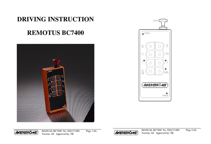
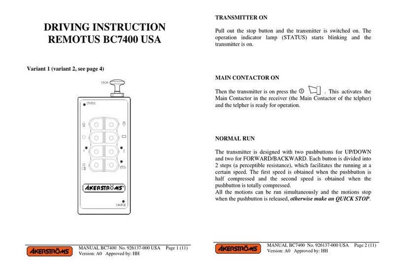
Akerstroms Jupiter Era 4B User manual

950455-000 EN/SV C0
OPERATING MANUAL/
ANVÄNDARMANUAL
REMOTUS JUPITER
Era 4/6/8B
(AQ80)

Revision History
Version Date Reason
A0 2014-05-20 1st released version
A1 2014-07-03 External power supply information, battery depleted alternation
B0 2014-11-18 Dig in 2 symbol on display moved next to dig in 1
C0 2015-08-12 External supply removed

MANUAL LANGUAGES 3 (32)
Jupiter Era 4B, 6B & 8B Document-ID: 950455-000 EN/SV
Version: C0 Author: SH
EN
SV
MANUAL LANGUAGES
Operating Manual JUPITER Era 4/6/8B 4
Tandem and multi-operator operation (only Era 8B - 9/10 Buttons) 13
Användarmanual JUPITER Era 4/6/8B 15
Tandem- och erförardrift (endast Era 8B - 9/10 Buttons) 24
TRANSMITTER OVERVIEW JUPITER Era 4/6/8B 26
Symbol layout overview Jupiter Era 4B & 6B 27
Symbol layout overview Jupiter Era 8B - 8/9 Buttons 28
Symbol layout overview Jupiter Era 8B - 10 Buttons 29
Symbol explanation / Symbolförklaring 30

Operating Manual JUPITER Era 4/6/8B 4 (32)
Jupiter Era 4B, 6B & 8B Document-ID: 950455-000 EN/SV
Version: C0 Author: SH
EN
OPERATING MANUAL JUPITER Era 4/6/8B
!The equipment has to be controlled by a qualied operator
1 MAINTENANCE
To maintain availability and operational safety, a regular maintenance is necessary on
the system.
Daily maintenance
Before each use of the transmitter, check the following items for faults or damages:
• Visual inspection of the transmitter enclosure (cracks, dents)
• Visual inspection of rubber cover for buttons (cracks)
• Broken/faulty buttons
• Visual inspection of carrying device
• Visual inspection of battery (cracks, dents)
• Test that the battery lock is functioning normally
• Test of safety stop button (it shall be intact and easy to move)
If there is any damage or fault contact an authorized service technician.
Weekly maintenance
• Clean the battery contacts and the contacts on the transmitter and
charger
• Clean the transmitters control panel and check that the print is still
readable
!For cleaning use a dry cleaning cloth, if necessary use a wet cleaning cloth
and a soap solution. Never use an alcohol-based product for cleaning;
it can seriously damage the plastic.

Operating Manual JUPITER Era 4/6/8B 5 (32)
Jupiter Era 4B, 6B & 8B Document-ID: 950455-000 EN/SV
Version: C0 Author: SH
EN
2 START THE TRANSMITTER AND ACTIVATE THE MAIN CONTACTOR
The following procedure has to be followed when starting the transmitter:
1. Make sure no buttons are pressed.
2. Pull up the STOP button.
3. The status indicator should show slow blinking green
(if not PIN locked)
4. Activate the main contactor (MC) in the receiver, push down the
button B7 (1st step).
The unit is now in operating mode.
3 PIN LOCKED
When PIN is enabled the transmitter will not start to transmit before the correct PIN
code is entered. If the transmitter is PIN locked at startup the status indicator shows
red continuous light. Display will show “Enter PIN”.
Enter the 4-digit PIN code by press B1 repeatedly to select number and B8 to choose
the number. Delete a number with button B2. When all 4-digit are selected, press B8
once again to select the PIN code.
At successful login the status indicator shows green ashing. Display shows “PIN
OK!”. The unit is now in operating mode. See installation manual for conguration
of the PIN lock.
4 NORMAL OPERATION
The transmitter is designed with two push buttons for HOIST Up/Down, TROLLEY
Left/Right and BRIDGE Forward/Reverse.
Each button is divided into 2 steps (a perceptible resistance) which facilitate the run-
ning at a certain speed. The rst speed is obtained when the push button is half com-
pressed and the second speed is obtained when the push button is totally compressed.
All the motions can be run simultaneously and the motions will be stopped when the
push button is released, if not make a forced STOP using the safety STOP button.

Operating Manual JUPITER Era 4/6/8B 6 (32)
Jupiter Era 4B, 6B & 8B Document-ID: 950455-000 EN/SV
Version: C0 Author: SH
EN
5 SIGNAL
A signal can be emitted at any time during the run and sounds as long as the push
button
is depressed (1st step).
Risk of high noise sound, hearing protection required.
6 EXTRA FUNCTION
Press button B7 to the 2nd step for extra function .
7 SLOW SPEED (MICRO) OPERATION AND EXTRA FUNCTION
Button B8, 1st step: Micro
Push in the button* to step one for Slow speed (micro) and the LED for Slow speed
will be lit. The objects motion will now only operate at a factory pre-set slow speed
regardless of the compression of the push buttons. The buttons are interlocked during
this time so that only one movement can be operated at a time. The other functions
work normally.
*For Era 8B “10 Buttons” press down the botton for 0.3 seconds.
Button B8, 2nd step: Extra function
Push in the button to step two for extra function.
8 DUPLEX
In a duplex system the transmitter gets information from the receiver and shows it on
the display, for example weight.
See “12.1 Display indications” on page 8.
9 STOP
Depress the safety STOP button for stop.

Operating Manual JUPITER Era 4/6/8B 7 (32)
Jupiter Era 4B, 6B & 8B Document-ID: 950455-000 EN/SV
Version: C0 Author: SH
EN
10 TRANSMITTER & MAIN CONTACTOR OFF
Depress the STOP button which switches off the transmitter. At the same time the
main contactor in the receiver is deactivated (the main contactor of the crane cuts
out). The status indicator light goes out.
11 AUTOMATIC SWITCH-OFF FUNCTION
The transmitter is equipped with automatic switch-off function, switching off the
transmitter after 2, 5, or 15 minutes after the latest use. It is also possible to set the
transmitter for continuous operation. The status indicator goes out and the main con-
tactor is deactivated upon automatic switch-off. Continued operation requires restart,
press down the stop button and wait a few seconds, then restart the transmitter.
See the Installation manual for instructions how to set the automatic switch-off time.
Low battery voltage will also cause automatic switch-off.
12 INDICATIONS
If the transmitter during start up (if not PIN locked) or while in operation detects a
fault in any of the transmitters self-tests it will indicate a continuous red light. After
that the transmitter powers down. If one of the push buttons has a fault during start-up
it indicates a continuous red light for 3 seconds after that the transmitter powers down.
INDICATIONS EXPLANATIONS
Greenashing Operating
Yellowquickashing Battery voltage low <3,5 V
Yellow continuous, during operating Battery empty
Transmitter will shut-off within 10s
Yellow continuous, at start-up Congurationmode
Red continuous at start-up PIN locked
Red continuous, during operating Hardware fault
Blue continuous,
other indications may occur simultaneously
High power

Operating Manual JUPITER Era 4/6/8B 8 (32)
Jupiter Era 4B, 6B & 8B Document-ID: 950455-000 EN/SV
Version: C0 Author: SH
EN
12.1 Display indications
These default symbols can appear on the display depending on the conguration.
Crane 1
14.1kg
1212AB
1 2 3 4
5
6
9
7 8
1. Radio signal / MC
2. SHIFT-selection (Era 8B 9/10 Buttons)
3. Text eld (crane id etc.)
4. Battery level
5. Dig. In 1 & 2 (shows if active)
6. Overload warning
7. Weight load graph (full-scale=max load)
8. Weight, up to 5 digits
9. Weight unit (kg,t or lb)
Radio signal quality
No radio link
established Weak signal Good signal Strong signal Very
strong signal
MC on is indicated by a line beneath the radio signal symbol, example .
Text eld (crane id etc.)
This text is congured in the receiver (8 characters). For knowing which crane the
transmitter is controlling.
Battery level
Battery empty 25% 50% 75% 100% (fully charged)
Weight / Graph / Overload
The weight is shown with the unit symbol kg, ton or lb. depending on the receiver
conguration.
The bar graph displays the weight load. Full scale= maximum load. The graph is only
shown if a maximum weight limit is congured in the receiver.
This symbol appears if the load on the crane reaches the weight limit (overload)
SHIFT-selection
Shows which selections that currently are active.

Operating Manual JUPITER Era 4/6/8B 9 (32)
Jupiter Era 4B, 6B & 8B Document-ID: 950455-000 EN/SV
Version: C0 Author: SH
EN
13 BATTERY
The transmitter is equipped with a status indicator showing battery status. The indica-
tor blinks slowly green when the battery voltage is normal, but starts to blink rapidly
yellow, when it gets low. When the indicator has started blinking rapidly yellow, the
transmitter can be operated for approximately 5-10 minutes before the voltage is so
low that the transmitter switches off automatically.
• Remove the battery from the charger when the power supply is turned off.
• A well maintained battery is necessary for faultless operation.
!The battery must not be charged if the temperature is lower than
+10ºC or higher than +45ºC.
!Only use chargers approved by the supplier.
!
Warning! If an incorrect battery type is used in the unit, the battery
may explode.
Disposal of a Li-Ion battery poses a smaller threat to the environment
when compared to other battery types. All used Li-Ion batteries should be
immediately sent to a qualied battery collection centre for recycling.
Depleted batteries shall be returned for recycling.
Exchange battery:
1
2
13.1 Charger instructions
Please read the documentation supplied with the charger for charging instructions.

Operating Manual JUPITER Era 4/6/8B 10 (32)
Jupiter Era 4B, 6B & 8B Document-ID: 950455-000 EN/SV
Version: C0 Author: SH
EN
14 CIM CARD
On the back of the MAIN board there is a connector for a “CIM card”. This is used
for storing conguration information. You can take out the CIM-module from one
system and place it in a spare transmitter with the same system program and it will
work exactly the same. This has to be done in a clean, dry and ESD safe environ-
ment.
!To avoid personal and/or property damages; exchange CIM card ONLY
when the transmitter battery has been removed.
!*Note that some settings does not follow with the CIM card and need to
be set in the “spare” transmitter. These settings are; Radio comm power,
FX sequence 0-119 and Remote type, refer to installation manual.
14.1 Removing/mounting CIM card
12
1. Remove the battery. Unscrew the 6 screws holding
together the enclosure.
2. The CIM card 1is located at the top of the
transmitter above the display board 2. Gently
remove the CIM card straight up.
3. Install the CIM card primarily in the original
transmitter, alternative spare transmitter. Be
sure to insert the CIM card properly in its
connector.
4. Reinstall the enclosure. The screws should be
tightened with 1 Nm.
5. Insert battery. Now, the transmitter is ready for
operation.

Operating Manual JUPITER Era 4/6/8B 11 (32)
Jupiter Era 4B, 6B & 8B Document-ID: 950455-000 EN/SV
Version: C0 Author: SH
EN
15 INSTRUCTIONS FOR CRANE OPERATORS
These instructions have to be followed.
!
Check that the radio transmitter operates on the crane that you are going to operate
(for instance give a signal). Check all functions of the radio transmitter.
!
Check that no unauthorized person is on or near the crane when you start to operate
it. Any blocking device at the entry of the crane should be closed.
!
Check the position of the symbols for operating direction
(crane-trolley-travel).
!
At the beginning of each shift the crane operator is to test all brakes, limit switches
and emergency stop functions as well as the STOP button on the transmitter.
!
The crane operator should when operating the crane stand at a suitable
distance from the crane hoist in order to have adequate overview of the
operation.
!
It is prohibited to move the crane load over oneself or coworkers.
Signal in order to warn others.
!
Avoid driving into end stops since equipment and goods can be damaged.
!
Check your own free passageway in order to avoid tripping over material on the
ground when you operate the crane. Keep the workplace in good order.
!
If you loose control of the crane movements, release the push buttons to obtain the
zero position in order to stop the crane. If the crane still does not stop, actuate the
STOP function.
!
Find out where the crane’s main power disconnect is, in order to be able to quickly
switch off if required.

Operating Manual JUPITER Era 4/6/8B 12 (32)
Jupiter Era 4B, 6B & 8B Document-ID: 950455-000 EN/SV
Version: C0 Author: SH
EN
!
Never hand over the transmitter to anyone who has not undergone training in radio-
control crane operation.
!
After completed operation you should always switch the transmitter off with STOP.
Note! Do not put the transmitter aside without switching the transmitter off with
STOP.
!
The main contactor of the crane is to be switched off after the end of working hours.
The transmitter is then to be kept inaccessible to unauthorized persons.
!
In case of faults or breakdowns in the radio control equipment the crane should per-
mit operation from the cab or with suspended operating gear. In such case rst turn
the switch from radio operation to manual operation. Make certain how this switch-
over is to be made before you start operating the crane.
!
Make sure that the receiver can not be activated when you service
the transmitter.
!
When working on the crane ensure that all radio transmitters and oth-
er controls are locked or otherwise under supervision
ALWAYS REPORT DEFECTS TO THE WORKPLACE MANAGEMENT.

Tandem and multi-operator operation (only Era 8B - 9/10 Buttons) 13 (32)
Jupiter Era 4B, 6B & 8B Document-ID: 950455-000 EN/SV
Version: C0 Author: SH
EN
TANDEM AND MULTI-OPERATOR OPERATION
(only Era 8B - 9/10 Buttons)
16 TANDEM OPERATION
Tandem operation means that two cranes can be operated from the same transmitter,
which makes it easier, for example to lift two objects simultaneously or a big object
using two cranes. The function and symbol layout of the transmitter for tandem opera-
tion is different from the standard.
17 MULTI-OPERATOR OPERATION
Multi-operator operation means that two transmitters can operate the same object. This
can be benecial, for example, when the view is blocked. The control of the object can
be passed between two transmitters. Active crane selection and deselection guarantees
that only one transmitter is in control of the object at a time. The function and symbol
layout of the transmitter for multi-driver operation is different from the standard.
18 START THE TRANSMITTER AND ACTIVATE THE MAIN CONTACTOR
The following procedure has to be followed when starting the transmitter:
1. Make sure no buttons are pressed.
2. Pull up the STOP button.
3. The status indicator should show slow blinking green (if not PIN locked).
4. Check that the crane/cranes are free to operate.
5. Selectcrane/s.Thersttransmitterthatmaketheselectioncan
operate the crane/s and the other transmitter will automatically be
blocked.
6. Activate the main contactor (MC) in the receiver, push down the
button B7 (1st step).
The unit is now in operating mode.

Tandem and multi-operator operation (only Era 8B - 9/10 Buttons) 14 (32)
Jupiter Era 4B, 6B & 8B Document-ID: 950455-000 EN/SV
Version: C0 Author: SH
EN
19 TRANSMITTER & MAIN CONTACTOR OFF
Deselect the crane/cranes before the transmitter is turned off, otherwise the transmitter
remains to block the crane/s selection. Depress the STOP button which switches off
the transmitter. At the same time the main contactor in the receiver is deactivated (the
main contactor of the crane cuts out). The status indicator light goes out. Operation can
now, if desired, be performed with another transmitter.
20 SELECT CRANE DURING OPERATION
1. Check that the crane/cranes are free to operate.
2. Selectcrane/s.Thersttransmitterthatmaketheselectioncan
operate the crane/s and the other transmitter will automatically be
blocked. To select crane/s press down the SHIFT-button B8 to 2nd
step and make the selection
3. Push down the button B7 (1st step) .
20.1 Era 8B - 9/10 Buttons Selection 1, 2 or 1+2
The SHIFT (B8) button, B5 and B6 are used for trolley selection.Selected trolley
is shown on the display. With SHIFT pressed down to 2nd step press down B5/B6 for
selection/deselection 1, 2 or 1+2.
Selection 1
Selection 2
20.2 Era 8B - 9 Buttons Selection A, B or A + B
The SHIFT (B8) button, B3 and B4 are used for crane selection. Selected crane is
shown on the display. With SHIFT pressed down to 2nd step press down B3/B4 for
selection/deselection A, B or A+B.
Selection A
Selection B

Användarmanual JUPITER Era 4/6/8B 15 (32)
Jupiter Era 4B, 6B & 8B Document-ID: 950455-000 EN/SV
Version: C0 Author: SH
SV
ANVÄNDARMANUAL JUPITER Era 4/6/8B
!Utrustningen får endast manövreras av kvalicerad operatör
1 UNDERHÅLL
För att upprätthålla tillgängligheten och driftsäkerheten är ett regelbundet underhåll
nödvändig på systemet.
Dagligt underhåll
Före varje användning av sändaren, kontrollera följande för fel eller skador:
• Visuell inspektion av kapsling (sprickor, bulor)
• Visuell inspektion av gummimattan för knapparna (sprickor)
• Trasiga/defekta knappar
• Visuell inspektion av bäranordningen
• Visuell inspektion av batteri (sprickor, bulor)
• Kontrollera att batterilåset fungerar normalt
• Kontrollera STOPP-knappen (den ska vara intakt och lätt att röra)
Om det nns några skador eller fel kontakta auktoriserad servicetekniker.
Veckovist underhåll
• Rengör batteriets kontakter samt kontakterna på sändaren och laddaren
• Rengör sändarens kontrollpanel och kontrollera att trycket fortfarande
är läsbart
!För rengöring använd en torr rengöringsduk, om nödvändigt använd en
våt rengöringsduk och tvållösning. Använd aldrig en alkohol-baserad
produkt för rengöring, det kan allvarligt skada plasten.

Användarmanual JUPITER Era 4/6/8B 16 (32)
Jupiter Era 4B, 6B & 8B Document-ID: 950455-000 EN/SV
Version: C0 Author: SH
SV
2 STARTA SÄNDARE OCH AKTIVERA HUVUDKONTAKTOR
Följande procedur måste följas vid start av sändaren:
1. Se till att inga knappar är nedtryckta.
2. Dra upp stoppknappen.
3. Sändarens statusindikator ska blinka långsamt grönt
(om inte PIN-låst).
4. Aktivera mottagarens huvudkontaktor genom att trycka ned
knapp B7 (steg 1).
Enheten är nu i driftläge.
3 PIN-LÅST
När PIN-lås är aktiverat kommer sändaren inte att börja sända förrän rätt PIN-kod är
angiven. Om sändaren är PIN-låst vid uppstart lyser statusindikeringen med ett fast
rött sken. Displayen visar ”Enter PIN”.
För att välja siffra tryck på knappen B1 upprepade gånger välj siffran med knapp B8.
För att radera en siffra tryck ned knapp B2. När alla 4 siffrorna är inmatade tryck
återigen på B8 för att välja PIN-koden.
Om rätt PIN-kod matas in börjar statusindikeringen att blinka grönt.
Displayen visar ”PIN OK!”. Enheten är nu i driftläge.
Se installationsmanualen för kongurering av PIN-lås.
4 NORMAL KÖRNING
Sändaren är designad med tryckknappar för:
LYFT lyft/sänk, TRALLÅK vänster/höger och KRANÅK fram/back,
där varje knapp är uppdelad i 2 steg (ett kännbart motstånd) som underlättar körning
i en viss hastighet. Första hastigheten erhålls när knappen är halvt intryckt och andra
hastigheten fås när knappen är helt intryckt. Flera rörelser kan köras samtidigt och
rörelserna stannar när knapparna släpps, i annat fall tryck ner STOPP-knappen.

Användarmanual JUPITER Era 4/6/8B 17 (32)
Jupiter Era 4B, 6B & 8B Document-ID: 950455-000 EN/SV
Version: C0 Author: SH
SV
5 SIGNAL
Signal kan ges när som helst under körningen och ljuder så länge tryckknappen
är intryckt (steg 1).
Risk för hörselskador, använd hörselskydd.
6 EXTRA FUNKTION
Tryck in knapp B7 till steg 2 för extra funktion .
7 LÅGFARTS (MIKRO) KÖRNING OCH EXTRA FUNKTION
Knapp B8, steg 1: Mikro
Tryck in knappen* för Lågfartskörning (mikro) och lysdioden för Lågfart tänds. Ob-
jektets rörelse går nu i en förinställd långsam fart oberoende av knapparnas nedtryck-
ning. Knapparna är förreglade så att endast en rörelse kan manövreras åt gången, icke
simultan. Övriga funktioner verkar som vid normalkörning.
*För Era 8B ”10 Buttons” tryck ner knappen till steg 1 i 0,3 sekunder.
Knapp B8, steg 2: Extra funktion
Tryck in knappen för funktion.
8 DUPLEX
I ett duplex system visar displayen på sändaren information ifrån mottagaren, exem-
pelvis vikt. Se ”12.1 Display indikering” på sidan 19.
9 STOPP
Stopp erhålles genom att trycka in STOPP-knappen.
10 STÄNG AV SÄNDARE & AVAKTIVERA HUVUDKONTAKTOR
För att stänga av sändaren tryck in STOPP-knappen. Då avaktiveras även huvudkon-
taktorn i mottagaren (mottagarens huvudkontaktor går ifrån).
Statusindikeringen för drift slocknar.

Användarmanual JUPITER Era 4/6/8B 18 (32)
Jupiter Era 4B, 6B & 8B Document-ID: 950455-000 EN/SV
Version: C0 Author: SH
SV
11 AUTOMATISK AVSTÄNGNING
Sändaren är försedd med automatisk avstängning som stänger av sändaren efter 2,
5, eller 15 minuter efter senaste användningen beroende på vilken tid som ställts in.
Även kontinuerlig drift kan ställas in. Vid utgången tid slocknar statusindikeringen och
huvudkontaktorn faller. För fortsatt drift krävs omstart, tryck in stopp-knappen vänta
några sekunder starta sedan om sändaren. Se installationsmanualen för inställning av
den automatiska avstängningstiden.
För låg batterispänning orsakar också automatisk avstängning.
12 SÄNDARINDIKERINGAR
Om sändaren vid uppstart (om inte PIN-låst) eller under drift upptäcker ett fel vid
någon av självtesterna indikeras detta med fast rött sken, varefter sändaren stänger
av sig. Indikeras fast rött sken i 3 sekunder vid uppstart är någon tryckknapp felaktig,
sändaren stänger av sig.
INDIKERINGAR FÖRKLARING
Grönt blinkande Drift, ok
Gult snabbt blinkande Batterispänning låg <3,5 V
Gult fast sken, vid uppstart Kongurationsläge
Gult fast sken, under drift Batteriet tomt
Sändaren stängs av inom 10s
Rött fast sken, vid uppstart PIN-låst
Rött fast sken, under drift Hårdvarufel
Blått fast sken,
andra indikationer kan förekomma samtidigt
Högeffekt

Användarmanual JUPITER Era 4/6/8B 19 (32)
Jupiter Era 4B, 6B & 8B Document-ID: 950455-000 EN/SV
Version: C0 Author: SH
SV
12.1 Display indikering
Dessa standardsymboler kan visas på displayen beroende på konguration.
Crane 1
14.1kg
1212AB
1 2 3 4
5
6
9
7 8
1. Radiosignal / HK
2. SHIFT-val (Era 8B 9/10 Buttons)
3. Textfält (kran-id etc.)
4. Batterinivå
5. Dig. In 1 & 2 (visas om aktiva)
6. Överbelastningsvarning
7. Viktbelastningsgraf (full skala=max belastning)
8. Vikt, upp till 5 tecken
9. Viktenhet (kg,t eller lb)
Radiosignal
Ingen radiolänk
etablerad Svag signal Bra signal Stark signal Mycket
stark signal
HK till indikeras av en linje under radiosignalens symbol, exempel .
Textfält (kran-id etc.)
Denna text nns kongurerad i mottagaren (8 tecken). För vetskapen om vilken kran
sändaren kontrollerar.
Batterinivå
Batteriet tomt 25 % 50 % 75 % 100 % (fulladdat)
Vikt/Graf/Överbelastning
Vikten visas med enhetenssymbol kg, ton eller lb. beroende på mottagarens kongu-
ration.
Stapeldiagrammet visar viktbelastning. Full skala = maximal belastning. Grafen visas
bara om en högsta viktgräns är kongurerad i mottagaren.
Denna symbol visas om belastningen på kranen når viktgränsen (överbelastning).
SHIFT-val (endast Era 8B 9/10 Buttons)
Visar vilka val (1,2,A,B) som för tillfället är aktiva.

Användarmanual JUPITER Era 4/6/8B 20 (32)
Jupiter Era 4B, 6B & 8B Document-ID: 950455-000 EN/SV
Version: C0 Author: SH
SV
13 BATTERI
Sändaren är försedd med indikeringslampa för batteristatus. Lampan blinkar lång-
samt grönt när batterispänningen är normal, men börjar blinka snabbt gult när den
blir låg. Efter det att indikeringslampan börjat blinka gult kan sändaren manövreras i
cirka 5-10 minuter innan spänningen är så låg att sändaren automatiskt stänger av sig.
• Ta batteriet ur laddaren när matningsspänningen bryts.
• En störningsfri drift kräver ett välskött batteri.
!Batteriet bör ej laddas om det har lägre temperatur än
+10 °C eller högre än +45 °C
!Använd endast av leverantören godkänd laddare.
!
Varning! Om en felaktig batterityp används i enheten
kan batteriet explodera.
Li-Jon-batterier är miljöanpassade, men bör som alla batterier lämnas in
för återvinning. Vid byte av batteri ska det förbrukade Li-Jon-batteriet
lämnas tillbaka till återförsäljaren där ett nytt batteri kan köpas. Då
erhålles också rätt ny typ av batteri.
Urladdade batterier ska lämnas till återvinning.
Byta batteri:
1
2
13.1 Laddningsinstruktioner
Läs dokumentationen som medföljer laddaren för instruktioner.
Other manuals for Jupiter Era 4B
2
This manual suits for next models
3
Table of contents
Languages:
Other Akerstroms Transmitter manuals
Popular Transmitter manuals by other brands

BD Sensors
BD Sensors DPS 200 Mounting instructions

Comet
Comet T8148 instruction manual

Vaisala
Vaisala GMM220 Series quick guide

Inovonics
Inovonics FA223S installation instructions

Sensor Electronics
Sensor Electronics SEC3120 Instruction and operation manual

Emerson
Emerson Rosemount 644h quick start guide