1.1 Sicherheit
1.2 Umwelt
2.1 Einleitung
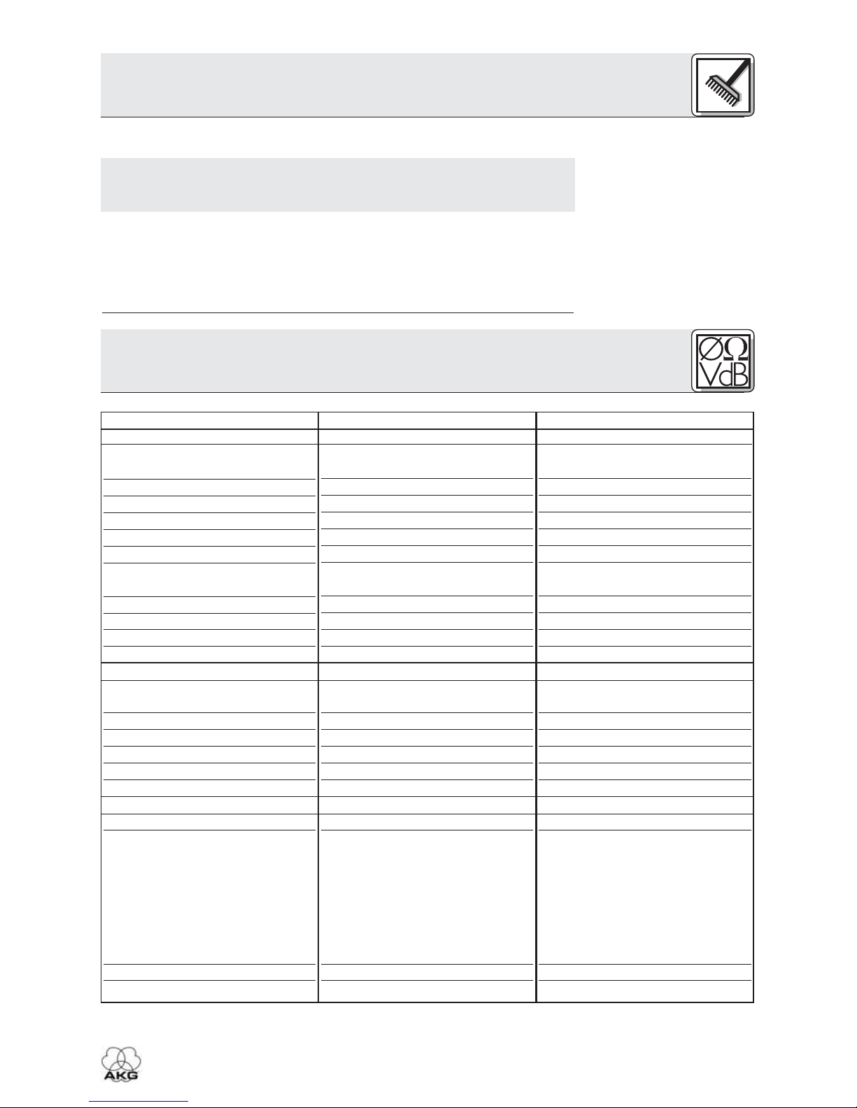
2.2 Lieferumfang
Tabelle 1: Headsets
und mitgeliefertes
Zubehör
2.3 Allgemeine
Beschreibung
• Überprüfen Sie bitte, ob das Gerät, an das Sie die Sprechgarnitur
anschließen möchten, den gültigen Sicherheitsbestimmungen ent-
spricht und mit einer Sicherheitserdung versehen ist.
1. Wenn Sie das Gerät verschrotten, entfernen Sie die Batterien bzw.
Akkus, trennen Sie Gehäuse, Elektronik und Kabel und entsorgen Sie alle
Komponenten gemäß den dafür geltenden Entsorgungsvorschriften.
2. Die Verpackung ist recyclierbar. Entsorgen Sie die Verpackung in einem
dafür vorgesehenen Sammelsystem.
Vielen Dank, dass Sie sich für ein Produkt aus dem Hause AKG ent-
schieden haben. Bitte lesen Sie die Bedienungsanleitung aufmerk-
sam durch, bevor Sie das Gerät benützen, und bewahren Sie die
Bedienungsanleitung sorgfältig auf, damit Sie jederzeit nachschlagen
können. Wir wünschen Ihnen viel Spaß und Erfolg!
Kontrollieren Sie bitte, ob die Verpackung alle zu Ihrem Modell gehö-
renden Teile enthält. Falls etwas fehlt, wenden Sie sich bitte an Ihren
AKG-Händler.
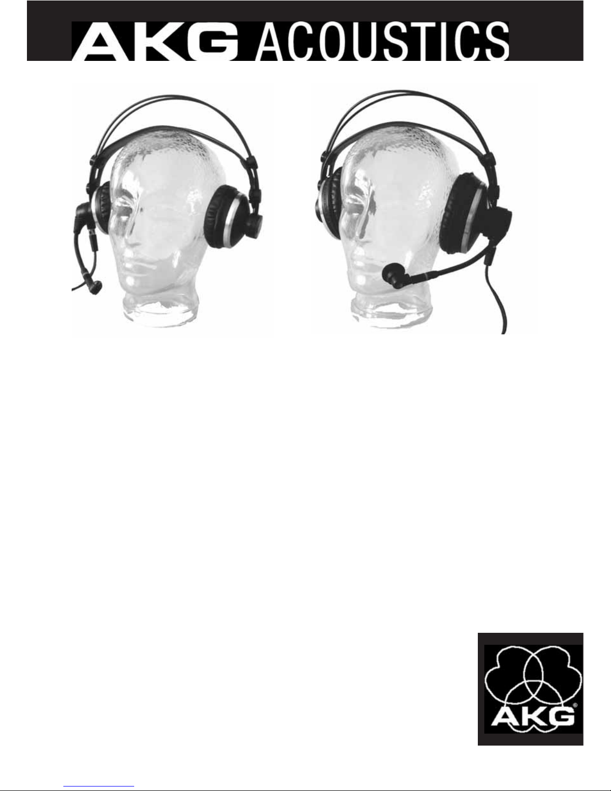
Jedes der professionellen Headsets HSC 171, HSC 271, HSD 171,
HSD 271 und HSD 271 Single besteht aus einem Kopfhörer der AKG
Studio-Serie und einem auf einem flexiblen Mikrofonarm montierten
hochwertigen dynamischen oder Kondensatormikrofon. Der Frequenz-
gang dieser Mikrofone ist speziell für Sprachübertragung ausgelegt und
gewährleistet eine hervorragende Tonqualität. Die elastische Lagerung
des Mikrofons garantiert eine weitgehende Unterdrückung von Han-
tierungsgeräuschen.
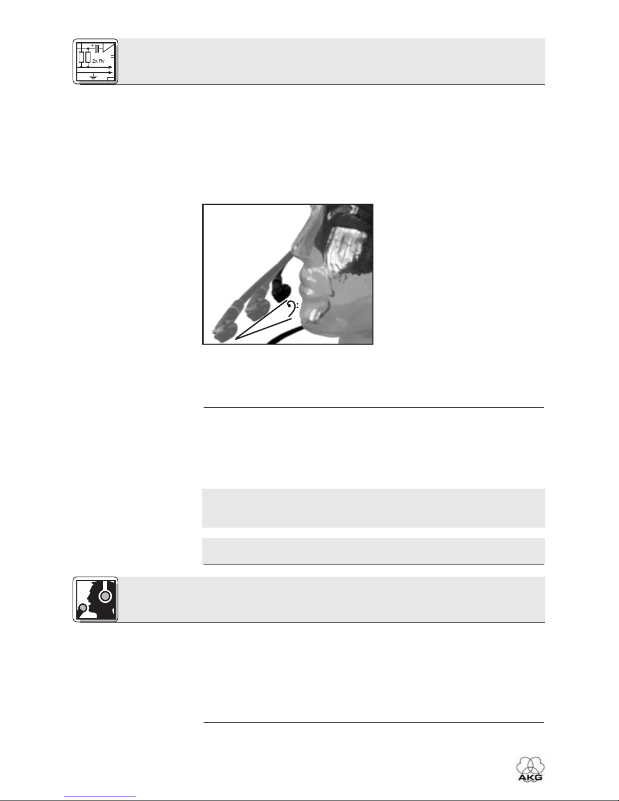
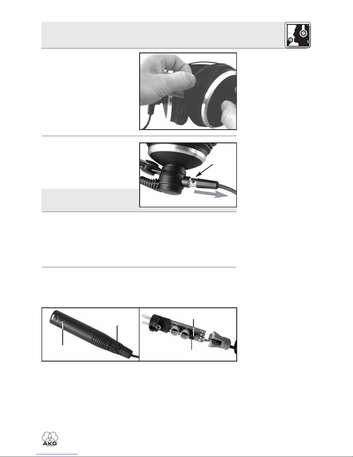
Der Mikrofonarm ist um 270° schwenkbar für rechts- oder linksseitiges
Tragen und mit einer Mikrofon-Stummschaltfunktion ausgerüstet.
2 Beschreibung
2HSC 171/271, HSD 171/271/Single
1 Sicherheit und Umwelt
HSC 171
1 x Headset
HSC 171
HSC 271
1 x Headset
HSC 271
HSD 171
1 x Headset
HSD 171
HSD 271
1 x Headset
HSD 271
HSD 271
Single
1 x Headset
HSD 271
Single
1 x Velours-
Ohrpolster
für
Kopfhörer
1 x Windschutz W 44 für
Mikrofon
1 x Anschlusskabel mit
Phantomspeiseadapter
HSC-PA für Mikrofon 1 x Anschlusskabel
2 x Velours-Ohrpolster für Kopfhörer
1 x Windschutz W HSD für Mikrofon