Instructions
GB
1572H402 Ed.04
351572402 REV.03 2012
AKO ELECTROMECÀNICA, S.A.L.
We reserve the right to supply materials slightly different to those described in our Data
Sheets. Updated information in our website: www.ako.com
Av. Roquetes, 30-38
08812 Sant Pere de Ribes
Barcelona (España)
www.ako.com
Tel. (34) 938 142 700
Fax (34) 938 934 054
AKO-15724 AKO-15725
1- Warnings
-The unit should be installed in a place protected from vibrations,
water and corrosive gases, where the ambient temperature does not
exceed the value indicated in the technical data.
-For the unit to operate correctly, use only the probes supplied by AKO.
-For the reading to be correct, the probe should be used in a place
without heat influences apart from the temperature you want to
measure or control.
-The probe and its cable should NEVER be installed in a conduit together
with power, control or feeder cables.
-In the event of lengthening the NTC probe, always used shield cable and
earth the mesh. In these cases, the maximum deviation will be 0.25 ºC
from -40 ºC to +20 ºC (Maximum 1000 m with a minimum section of
2
0.5 mm ). We recommend using AKO-15586 cable.
-Always disconnect the power supply to do the wiring.
-The power circuit should be equipped with a switch marked as
disconnecting device of the equipment of at least 2 A, 230 V, situated
near the appliance.
-The power supply cable should be H05VV-F or H05V-K type. The gauge
will depend on local regulations, but should in no case be less than
2
1 mm . The electrical installation should be carried out under pipe.
-Using the logger not observing the manufacturer's instructions may
alter the appliance safety requirements. Only probes supplied by AKO
should be used for the appliance to operate correctly.
2- Installation
In programming, confirms the selection and saves the entered value.
N + P keys : Pressing for over 10 seconds accesses the data log
display menu.
Press N / Q to select the log block and press SET to access it. Press
N / Q to select the log to be displayed, after 1 second the value of
each input will be displayed, indicating the date and time of the log.
N + O keys : Pressing for over 10 seconds accesses the alarms log
display menu.
Press N / Q to select the input to be displayed and press SET. Press
N / Q to select the event to be displayed (no. 1 is the most recent
event), after 1 second the value of each input will be displayed,
indicating the date and time of the event.
N + Q keys: Pressing them for over 10 seconds accesses the
programming menu.
1
2
2
2
60
41,5
94
125,535
ø max. 3,7
171
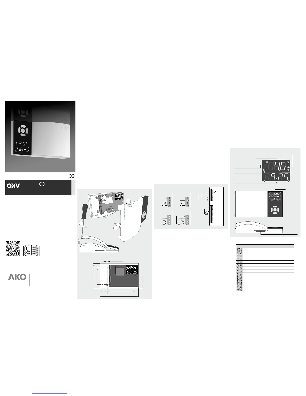
3
SET
Display
Temperature
indication
Time indication
Alarm active
Communication
with SD card
Maximum and minimum
temperature indicator
Active event
(digital input)
Browser
Slot for
SD card
3- Technical specifications
Power supply . . . . . . . . . . . . . . . . . . . . . . . . . . . . 90-240 V~ 50/60Hz
Alarm relay .........................8 A cos j=1
NTC range (AKO-14931)...............-50 ºC to 99.9 ºC
Range 4-20 mA . . . . . . Configurable from -100 to 900 (1000 levels)
Resolution . . . . . . . . . . . . . . . . . . . . . . . . . . . . . . . . . . . . . . . . . . 0,1
Accuracy class (-40 ºC to 40 ºC): . . . . . . . . . . ±1 ºC acc/ EN 12830
Response time: ......................< 20 seconds
Maximum relative time error: . . . . . . . . . . . . . . . . . . . . . . . . . < 0.1 %
Marked according to UNE-EN 12830 .......S,A,1,-40 ºC + 40 ºC
. . . . . . . . . . . . . . . . . . . . . . . . . . . . . . . . . . . Apt for use in storage (S)
. . . . . . . . . . . . . . . . . . . . . . . . . . . . . . . Climatic environment type (A)
. . . . . . . . . . . . . . . . . . . . . . . . . . . . . . . . . . . . . . . Accuracy class (1)
Maximum input power . . . . . . . . . . . . . . . . . . . . . . 8.5 VA
Working ambient temperature ...............0 ºC to 40 ºC
Storage ambient temperature ..............-20 ºC to 60 ºC
Degree of protection . . . . . . . . . . . . . . . . . . . . . . . . IP40
Double insulation between power supply, secondary circuit and relay
output.
Installation category .................II acc/ EN 61010-1
Pollution degree ...................II acc/ EN 61010-1
Maintenance of date and time without power supply ...Up to 2 days
Internal buzzer ......................70dB at 30 cm
SD cards accepted . . . . . . . . . . . . . . . . SD/SDHC (FAT / FAT32)
4- Wiring
5- Operation
Key function
N key
cording to parameter P50).
: A short press displays the maximum value reached in the last
24h, and the time when all the active inputs were reached.
In the programming menu it allows scrolling around the different levels,
or during the setting of a parameter, changing its value.
Q key: A short press displays the minimum value reached in the last
24h, and the time when all the active inputs were reached.
In the programming menu it allows scrolling around the different levels,
or during the setting of a parameter, changing its value.
O key: A short press downloads the data of the ongoing log onto the SD
card (if it has been inserted)
P key: A short press downloads ALL the logged data onto the SD card (if
it has been inserted). The save without changes, return to previous level
or exit programming parameter appears on the programming menu.
SET key: A short press downloads the data of the last log onto the SD
card (if it has been inserted).
Silences the acoustic alarm (ac
8 A
Gnd
Gnd
Tr+
Tr -
+15V
+15V
+15V
+
+
+
_
_
AKO-80040
AKO-80013
+
+
+
s
s
s
s
s
s
S1
S1
S1
DI1
4-20 mA
2 wires pasivo
4-20 mA
2 wires active 4-20 mA
3 wires
Digital
inputs
Modbus
(Only AKO-15725)
NTC S2
S2
S2
DI2
1 6
6 6
66
2 7
7 7
77
3 8
8 8
88
4 9
9 9
99
5 10 11 12
AKO-15724 / AKO-15725
90-240 V~
50/60 Hz
MESSAGES
Error accessing the logger's internal memory
Probe 2 broken (Open, crossed circuit or probe out of range)
Input disabled
Top log reached
Bottom log reached
Probe 1 broken (Open, crossed circuit or probe out of range)
SD card not detected
Writing error in SD card
Error in access to the real time clock (RTC)
Error in the format of the SD card. It must be FAT/FAT32
The SD card is write protected
Password request
Reading information from the internal memory.
Internal memory empty
Message table
For further information, refer to the application note available in our website
www.ako.com
http://www.ako.com/w4pu/page/qr/?qrcode=AKODOC0002