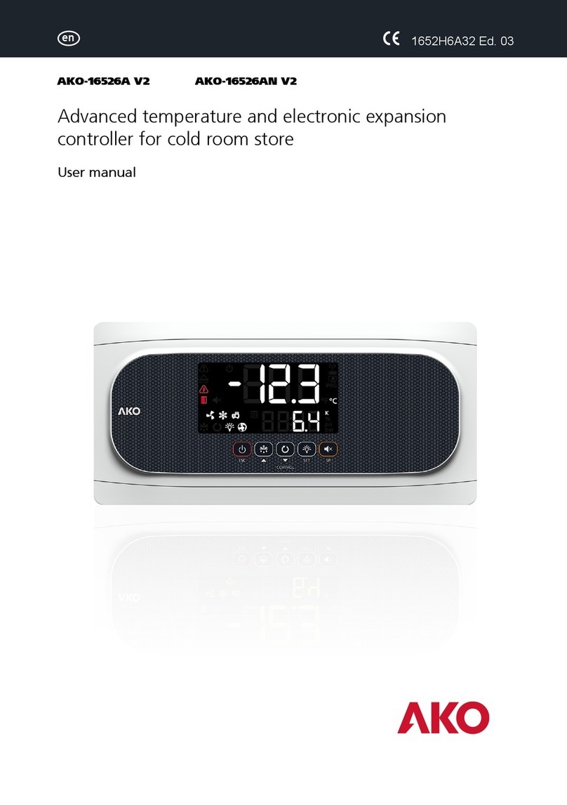
AKO AKO-21006 User manual

2100H602 Ed.01 we make it easy
AKODUO User Manual
The new generation of controllers for compressor
racks
GB

2
Minimum requirements
Chapter 1: Introduction
Chapter 2: Control unit: DUOControl
Chapter 3: User terminal: DUOVision
Chapter 4: Compressor regulation
Chapter 5: Fan regulation
Chapter 6: Alarm management
Chapter 7: Other functionalities
Appendix A: Technical specifications
Appendix B: Selection of the DUOControl controller
Appendix C: User parameters
Appendix D: Cable for connection to the local MODBUS network
Page 3
Page 6
Page 31
Page 84
Page 89
Page 93
Page 96
Page 98
Page 105
Page 107
Page 116
we make it easy
AKO Electromecànica thanks you and congratulates you on the purchase of our product, the development and manufacture of which
involved the most innovative technologies, as well as rigorous production and quality control processes.
Our commitment to achieving customer satisfaction and our continuous efforts to improve day by day are confirmed by the various quality
certificates obtained.
This is a high performance, technologically advanced product. Its operation and the final performance achieved will depend, to a great
extent, on correct planning, installation, configuration and commissioning. Please read this manual carefully before proceeding to install it
and respect the indications in the manual at all times.
Only qualified personnel may install the product or carry out technical support.
This product has been developed for use in the applications described in the manual. AKO Electromecànica does not guarantee its
operation in any use not foreseen in this document and accepts no liability in the case of damage of any type which may result from
incorrect use, configuration, installation or commissioning.
Complying with and enforcing the regulations applying to installations where our products are destined to be used is the responsibility of
the installer and the customer. AKO Electromecànica accepts no liability for damage which may occur due to failure to comply with these
regulations. Rigorously follow the instructions described in this manual.
In order to extend the lifetime of our products to the maximum, the following points must be observed:
Do not expose electronic equipment to dust, dirt, water, rain, moisture, high temperatures, chemical agents or corrosive
substances of any type.
Do not subject equipment to knocks or vibrations or attempt to handle them in any way differently to that indicated in the
manual.
Do not under any circumstances exceed the specifications and limitations indicated in the manual.
Respect the indicated environmental conditions for operation and storage at all times.
During installation and on completion of this, avoid the presence of loose, broken or unprotected cables or cables in poor
condition. These may constitute a risk for the equipment and its users.
AKO Electromecànica reserves the right to make any modification to the documentation and the product without prior notification.

3
1.- INTRODUCTION
The AKODUO controller family forms part of the new generation of electronic controls for regulating the
capacity of refrigerating plant.
DUOControl carries out the management of the installed components, the detection of alarms and the
recording of events (historical log of alarms and hours of operation of the compressors).
As display units, DUOControl enables the use of the DUOVision terminal and AKO-5004 Server Software.
La nueva generación de controladores para centrales de compresores
The new controllers generation for compressor racks and condenser fans
AKO-21006: Control unit with 6 outputs
AKO-21012: Control unit with 12 outputs
AKO-21018: Control unit with 18 outputs
DUOVision: User terminal
we make it easy

4
GENERAL CHARACTERISTICS
Usability: A family of products especially designed to make configuration and monitoring of
refrigeration plant easy.
Modularity: Model selection according to current and future needs.
Reliability: Use of automation technology as Control Hardware.
Unlimited number of operations: Control with transistor outputs (TRT).
Connectivity: Enables MODBUS connection for remote control / monitoring (AKO-5004).
DUOControl
Designed for refrigerating plant with compressors of equal characteristics
Flexible wiring: Multiple compressor – fan configurations
Up to 6 compressors (with up to 4 stages each)
Up to 8 fans
Compressor ON/OFF control
Fan ON/OFF or inverter control: 4-20 mA output with built in PI Control
Algorithms for compressor rotation: Sequential or by hours of operation
Algorithm for fan rotation: Sequential
Selectable algorithm for compressor control: Neutral Zone or Proportional Band
Selectable algorithm for fan control: Neutral Zone or Proportional Band
3 Inputs for 4-20 mA probes: Evaporation pressure, Condensation pressure and Air ambient
temperature
Floating condensation
Pump-Down: By time or level
Energy saving: Programmable interval synchronised with the internal real time clock
Options for working with any refrigerant gas in bar, and in bar and °C with R404A -
R134A - R717 - R22 - R410A - R507A - R744 (CO )
2
Reading of probes in the analogue input module itself
we make it easy

5
Safety circuit for each element controlled (compressors, fans and inverter)
3 Fixed digital Inputs: General high pressure switch, General low pressure switch and
Manual/Automatic selector.
Alarm RY Output (provided an output is available depending on configuration)
DIN rail mounting
2 User terminals: DUOVision or AKO-5004
Programming assistant: Basic installation configuration.
Input/Output test: Wizard for checking input/output wiring.
Dual multicolour graphic screen: Provides more information than conventional Displays.
Dynamic display of compressor and fan status
Intuitive menus with on-screen help: System programming without the instruction manual.
7-key navigator
Password for access to configuration parameters
DUOVision
we make it easy

6
2.- Control unit: DUOControl
The family of DUOControl controllers is made up of:
AKO-21006 Controller with 6 outputs made up of:
1 AKO-21801 Module: Control unit with 8 digital inputs and 6 digital outputs
1 AKO-21802 Module: Extension unit with 3 inputs and 1 output at 4-20 mA
AKO-21012 Controller with 12 outputs made up of:
1 AKO-21801 Module: Control unit with 8 digital inputs and 6 digital outputs
1 AKO-21802 Module: Extension unit with 3 inputs and 1 output at 4-20 mA
1 AKO-21803 Module: Extension unit with 2 digital inputs and 6 digital outputs
AKO-21018 Controller with 18 outputs made up of:
1 AKO-21801 Module: Control unit with 8 digital inputs and 6 digital outputs
1 AKO-21802 Module: Extension unit with 3 inputs and 1 output at 4-20 mA
2 AKO-21803 Modules: Extension unit with 2 digital inputs and 6 digital outputs
we make it easy

7
When you purchase an AKO-21006/12/18 you receive all the modules which make them up, although each
of the modules can also be purchased separately.
The following table summarises the composition of the three DUOControl models.
It is recommended that the connection be made when all the modules have been fixed to
the DIN rail to prevent breakage of the flat cables.
2.1.- INTERCONNECTION OF THE MODULES
The modules are connected together using the side connector on each module:
CONTROL UNIT
4-20 mA UNIT
DIGITAL UNIT
DIGITAL INPUTS
DIGITAL OUTPUTS
4-20 mA INPUTS
4-20 mA OUTPUTS
AKO-21006
8
6
AKO-21012
AKO-21801
AKO-21802
1 x AKO-21803
10
12
3
1
AKO-21018
2 x AKO-21803
12
18
we make it easy

8
The position each of the modules needs to occupy is shown below:
we make it easy AKODUO we make it easy AKODUO
we make it easy AKODUO
we make it easy AKODUO we make it easy AKODUO we make it easy AKODUO
The modular design of DUOControl enables a controller to be expanded by adding a new AKO-21803
module to its right, up to a maximum of 2. Likewise, it is also possible to remove one of the AKO-21803
modules.
Example: By adding 1 x AKO-21803 module, the AKO-21006 controller becomes an
AKO-21012. If one more of these modules is added (2 in total), this controller becomes an
AKO-21018.
AKO-21006
AKO-21012
AKO-21018
AKO-21801 AKO-21802 AKO-21803 AKO-21803
Equipment / Modules
we make it easy

9
2.2.- TECHNICAL DESCRIPTION OF THE MODULES
AKO-21801
Module responsible for carrying out the following tasks:
SOFTWARE
Control of Inputs / Outputs.
Algorithm for compressor and fan control.
Alarm management.
Recording of events (Alarm log).
MODBUS communication in slave mode.
Communication with the user terminal (DUOVision and AKO-5004).
HARDWARE
DUOVision communication interface.
MODBUS communication interface.
Interface for connecting to other modules.
8 Insulated Digital Inputs.
6 Insulated transistor Digital Outputs.
Appendix A includes the technical specifications for this module.
we make it easy

10
1.- Position of the DIN rail.
2.- Module earth connector.
3.- DIN rail clamp.
4.- Upper terminal block.
5.- Interface for communication with other modules.
6.- Lower terminal block.
D1.- Module status display.
POWER LED always ON in normal operation.
RUN LED always ON in normal operation.
ERR LED always OFF in normal operation.
Appendix A includes the technical specifications for this module.
The purpose of each of the terminals is described in Section 2.3.
D2.- Status LEDs for the digital Inputs and
Outputs.
INPUT with LED ON: +24 V in the
corresponding terminal.
INPUT with LED OFF: 0 V in the
corresponding terminal.
OUTPUT with LED ON: +24 V in the
corresponding terminal.
OUTPUT with LED OFF: 0 V in the
corresponding terminal.
we make it easy

11
AKO-21802
Module for managing 4-20 mA inputs and outputs.
1.- Position of the DIN rail.
2.- Module earth connector.
3.- DIN rail clamp.
4.- Upper terminal block (3 x 4-20 mA Inputs).
5/6.- Interface for communication with other modules.
7.- Lower terminal block (1 x 4-20 mA Output).
8.- Button to select the input to be shown on the module Display.
The Display (D) makes it possible to see the current flowing through each of the inputs and
outputs. The input or output desired is selected using the button (8).
we make it easy

12
1.- 4-digit display with one decimal.
2.- Digit to indicate the input or output to which the value corresponds. The value of this will increase on
pressing the button (8).
0 — 4-20 mA input current from the evaporation pressure probe.
1 — 4-20 mA input current from the condensation pressure probe.
2 — 4-20 mA input current from the Ambient air temperature probe.
4 — 4-20 mA output current to control the fan inverter.
Do not take the values on Display (D) into account when this digit is any other than the values
mentioned.
Appendix A includes the technical specifications for this module.
The purpose of each of the terminals is described in Section 2.3.
1
2
we make it easy

13
1.- Position of the DIN rail.
2.- DIN rail clamp.
3.- Upper terminal block (2 Digital Inputs and 2 Digital Outputs).
4/5.- Interface for communication with other modules.
6.- Lower terminal block (4 Digital Outputs).
D.- 8 LEDs representing the voltage present in each terminal:
LED ON: +24 V present in the corresponding terminal.
LED OFF: 0 V present in the corresponding terminal.
SUPPLY LED: Lit when the module is connected and correctly supplied with power.
Appendix A includes the technical specifications for this module.
The purpose of each of the terminals is described in Section 2.3.
AKO-21803
Extension module for digital inputs and outputs.
2 Digital Inputs
6 Digital Outputs
we make it easy

14
2.3.- WIRING TERMINALS
The following figure shows the layout of the terminals and their labelling.
Terminal
Function Controller
Label
AKO-21018
AKO-21012 Controller
Label
Terminal
Function
AKO-21802 AKO-21803 AKO-21803 AKO-21801
AKO-21802 AKO-21803 AKO-21801
we make it easy

15
AKO-21006
The terminals for the AKO-21801 and AKO-21802 modules always have the same notation. In
the case of AKO-21803 modules, the notation of the terminals depends on the position
occupied.
Fixed wiring terminals: Not depending on the
installation.
NC: Not connected
TU+: Connection to the DUOVision user
terminal
TU-: Connection to the DUOVision user
terminal
TUS: Connection to the DUOVision user
terminal
24V: +24 V supply from the control panel
0V: 0 V line from the control panel
T: Earth from the control panel
I1: General high pressure switch
I2: General low pressure switch
I3: MANUAL/AUTOMATIC selector from
the control panel
Terminals can be classified as follows, according to their function:
Variable wiring terminals: Vary according to the
installation.
I4 – I12: Connection depends on the
installation
O1 – O18: Connection depends on the
installation
4-20 mA input and output terminals:
VAR+/VAR-: Inverter for the fans
PE+/PE-: Suction probe
PC+/PC-: Discharge probe
TE+/TE-: Ambient air temperature
probe
Terminal
Function
Controller
Label
AKO-21802 AKO-21801
we make it easy

16
2.3.1.- FIXED WIRING TERMINALS
The recommended wiring for the fixed wiring terminals is shown below:
The general high and low pressure switchs are connected to terminals I1 and I2 respectively. The type of
contact for each of these inputs can be configured by means of the user parameters ENTR_1 and
ENTR_2. For further information, see Section 3.3.6.
The MANUAL/AUTOMATIC selector is connected to terminal I3.
MANUAL: Voltage of +24 V in terminal I3.
AUTOMATIC: Voltage of 0 V in terminal I3.
Their function is described in Section 7.4.
Terminals connected to a cross have no function allocated and are not connected.
The terminals not yet connected are dealt with in the next section.
we make it easy

17
2.3.2.- VARIABLE WIRING TERMINALS (I4-I12 and O1-O18)
The wizard (Section 3.1.) allocates the function to each of the variable wiring terminals. This
allocation depends on the following parameters of the refrigeration installation:
No. of Compressors (user parameter CONF_1)
No. of Stages per compressor (user parameter CONF_2).
No. of Fans or inverter use (user parameters CONF_5 and CONF_6).
Alarm output (parameter CONF_4).
Examples of a safety circuit for a compressor:
+24 V +24 V
C1
C1
C1 C1
+24 V +24 V
T-C1 T-C1
Thermistor Thermistor
Switch
Oil Pressure
Differential
Switch
Oil Pressure
Differential
SIMPLIFICATION
Contact type can be
c o n f i g u r e d b y
means of parameter
ENTR 3
All the variable wiring terminals are via transistors to permit an unlimited number
of operations.
Therefore, it is necessary to connect a 24 V relay to each of these terminals. The
use of plug-in relays is recommended to make replacement easier in the case of
failure.
The compressors, fans and the inverter (if used) have a safety circuit to protect the
installation against anomalous situations. All these are connected to the digital
input terminals (I4 – I12) as defined in the tables on pages 23 to 27.
we make it easy

18
The tables on pages 23 to 27 show the maximum number of fans which can be controlled in each type of
refrigerating plant.
Example: Consider a refrigerating facility with:
No. of Compressors = 2
No. of Stages per compressor = 2
With an AKO-21012 controller, it is possible to control up to 5 fans.
With an AKO-21018 controller, the number of fans can be increased
If less than the maximum number of fans permitted are used, the remaining terminals are left unconnected.
Compressors
Stages
I 4
I 5
I 6
I 7
I 8
I 9
I 10
I 11
I 12
1 1 T-C1 T-V1 T-V2 T-V3 T-V4 T-V5 T-V6 T-V7 T-V8
12T-C1 T-V1 T-V2 T-V3 T-V4 T-V5 T-V6 T-V7 T-V8
13 T-C1 T-V1 T-V2 T-V3 T-V4 T-V5 T-V6 T-V7 T-V8
14 T-C1 T-V1 T-V2 T-V3 T-V4 T-V5 T-V6 T-V7 T-V8
21T-C1 T-C2 T-V1 T-V2 T-V3 T-V4 T-V5 T-V6 T-V7
2 2 T-C1 T-C2 T-V1 T-V2 T-V3 T-V4 T-V5 T-V6 T-V7
23 T-C1 T-C2 T-V1 T-V2 T-V3 T-V4 T-V5 T-V6 T-V7
24 T-C1 T-C2 T-V1 T-V2 T-V3 T-V4 T-V5 T-V6 T-V7
FANS CONTROLLED ON/OFF
1 1 T-C1 T-V1 T-V2 T-V3 T-V4 T-V5 T-V6
12T-C1 T-V1 T-V2 T-V3 T-V4 T-V5 T-V6
13 T-C1 T-V1 T-V2 T-V3 T-V4 T-V5 T-V6
14 T-C1 T-V1 T-V2 T-V3 T-V4 T-V5 T-V6
21T-C1 T-C2 T-V1 T-V2 T-V3 T-V4 T-V5
2 2 T-C1 T-C2 T-V1 T-V2 T-V3 T-V4 T-V5
23 T-C1 T-C2 T-V1 T-V2 T-V3 T-V4 T-V5
24 T-C1 T-C2 T-V1 T-V2 T-V3 T-V4
Compressors
Stages
I 4
I 5
I 6
I 7
I 8
I 9
I 10
FANS CONTROLLED ON/OFF
Maximum number
of fans when using
the c o n t r o l l e r
AKO-21012
Maximum number of fans when using the
AKO-21018 controller
Detail of the table of inputs for the AKO-21012
Detail of the table of inputs for the AKO-21018
we make it easy

Example: Consider a refrigerating facility with:
No. of Compressors = 2
No. of Stages per compressor = 2
No. of Fans = 3 (ON/OFF control)
DUOControl Model: AKO-21012
Terminals I9 and I10 are left unconnected.
19
1 1 T-C1 T-V1 T-V2 T-V3 T-V4 T-V5 T-V6
12T-C1 T-V1 T-V2 T-V3 T-V4 T-V5 T-V6
13 T-C1 T-V1 T-V2 T-V3 T-V4 T-V5 T-V6
14 T-C1 T-V1 T-V2 T-V3 T-V4 T-V5 T-V6
21T-C1 T-C2 T-V1 T-V2 T-V3 T-V4 T-V5
2 2 T-C1 T-C2 T-V1 T-V2 T-V3 T-V4 T-V5
23 T-C1 T-C2 T-V1 T-V2 T-V3 T-V4 T-V5
24 T-C1 T-C2 T-V1 T-V2 T-V3 T-V4
Compressors
Stages
I 4
I 5
I 6
I 7
I 8
I 9
I 10
FANS CONTROLLED ON/OFF
Detail of the table of inputs for the AKO-21012
Unconnected terminals
A
Compressors
Stages
O 1
O 2
O 3
O 4
O 5
O 6
O 7
O 8
O 9
O 10
O 11
O 12
1 1 C1 V1 V2 V3 V4 V5 V6 Ry_A
12C1 C1a V1 V2 V3 V4 V5 V6 Ry_A
13 C1 C1a C1b V1 V2 V3 V4 V5 V6 Ry_A
14 C1 C1a C1b C1c V1 V2 V3 V4 V5 V6 Ry_A
21C1 C2 V1 V2 V3 V4 V5 Ry_A
2 2 C1 C1a C2 C2a V1 V2 V3 V4 V5 Ry_A
23 C1 C1a C1b C2 C2a C2b V1 V2 V3 V4 V5 Ry_A
FANS CONTROLLED ON/OFF
Detail of the table of outputs for the AKO-21012
Unconnected terminals
B
we make it easy

20
The digital inputs and outputs from the above example are connected as follows:
B
A
B
a a
we make it easy
This manual suits for next models
2
Other AKO Controllers manuals