Akron Brass 9015 User manual

704607
INSTRUCTION MANUAL
AND PARTS LIST
WATER FLOW TEST KIT
STYLE 9015

OPERATION
1. Determine criteria for your testing from NFPA or ISO publications, or other authority.
2. Connect Test Kit swivel inlet to hydrant or other fixed 2 1/2” discharge device. (For best results, the test kit should be preceded
by minimum 3 foot long straight, open 2 1/2” waterway.)
3. Loosen thumbscrews and rotate pitot blade out of stream position.
4. Select from the Discharge Table, the preferred tip diameter for the expected flow. Install the tip as follows:
a. Unscrew lock ring.
b. Pull out gray tip. (Caution: do not use tools which may damage waterway).
c. Insert proper size tip completely until retaining ring is snug against nozzle body.
d. Screw on lock ring clockwise until tight.
caution:
failure to replace lock ring may allow tip to
blow out, causing damage or injury.
5a. Hydrant: Open hydrant and flush rocks, etc. Rotate blade back into center of stream and tighten thumbscrew. Record
pressure reading.
5b. Pumper: After warm-up, bring pump up to desired speed and close throttling valve(s) to set discharge pressure at required rating.
Rotate pitot blade into stream center and tighten thumbscrew. Record pressure reading.
6. When hydrant or pumper must continue to operate (e.g. endurance test), rotate blade out of stream between readings to reduce
wear and avoid damage.
7. Read flow at intersection of tip size and pressure in Table. DO NOT apply additional hydrant coefficients since the nozzle tip
replaces the hydrant outlet as the orifice.
8. After use, open bleeder valve and drain any water in the pitot air chamber. Draining is especially important in freezing weather.
2

NOTE: When ordering replacement tips check retaining ring (#17) and O-Ring (#19)
** For other threads order by description and thread size (ODM and TPI) or by Akron Thread Code.
†† Package of 50 Ball Bearings - P/N 109041.
† Parts included in Pitot Blade Replacement Kit - P/N 110086. Kit includes reusable
Alignment Fixture - P/N 7-12-269
* Tips not part of standard unit. Only tips in standard units are U.L. Classified.
Parts List
ITEM NO. DESCRIPTION PART NUMBER QUANTITY
13/4”/19mm tip 9015-0015 1
115/16”/23.8mm tip* 9015-0016 1
11”/25mm tip* 9015-0017 1
11 1/8”/28.5mm tip 9015-0018 1
11 1/4”/31.8mm tip* 9015-0019 1
11 1/2”/38.1mm tip 9015-0020 1
11 3/4”/44.5mm tip 9015-0021 1
11 7/8”/47.6mm tip* 9015-0024 1
12”/50.8mm tip 9015-0022 1
12 1/4”/57.2mm tip 9015-0023 1
2 Body 110283 1
3Set Screw 7-42-023 1
42 1/2” Inlet Swivel (NH) ** 101420 1
5 Gasket 7-17-043 1
6Ball Bearings †† 39
7Bleeder Valve 7-79-045 1
8Thumb Screw 7-67-110 1
9Pitot Adapter Tube 110098 1
10 Stop Screw 7-67-111 1
11 Pressure Gauge - PSI/kPa 7-18-183 1
12 Quick Connect - 1/4” Socket 7-07-169 1
13 Quick Connect - 1/4” Plug 7-07-170 1
14† O-Ring 7-57-022 1
15† Set Screw (cup point) 7-65-024 1
16† Pitot Blade 110087 1
17 Retaining Ring 7-56-089 1
18 Lock Ring 109227 1
19 O-Ring 7-57-239 1
20† Set Screw (dog point) 7-65-117 1
21 O-Ring 7-57-052 1
22 Label 7-73-247 1
–Carry Case w/Liner 7-07-311 1
–Instruction Manual 7-04-607 1
–Laminated Discharge Table 7-07-328 1
3

4

MAINTENANCE
Maintenance requirements will vary widely depending on conditions and amount of service.
1. Lubricate seals, bearing surfaces and swivel occasionally with light machine oil or spray lubricant.
2. Check pitot gauge against a test gauge regularly.
REPAIR
PROBLEM ACTION
1. Pitot blade or tip damaged. 1. Replace. Instructions and alignment fixture provided with replacement blades.
2. Leak around lock ring. 2. Replace tip O-Ring.
3. Leak thru bleeder valve. 3. Replace O-Ring.
4. No reading on 4. Check for obstruction in
pressure gauge. Pitot Blade waterway.
Clean coupling and gauge stem. Replace gauge if necessary.
5

SUGGESTED NOZZLE TIP SIZE
TYPICAL PUMPER TESTS* (GPM)
NET NOZZLE PITOT
PUMP TIP PRESSURE
PRESSURE SIZE PSI GPM
500 GPM PUMPER
100% rated capacity 150 1 1⁄2” 58 508
70% rated capacity 200 1 1⁄8” 88 351
50% rated capacity 250 1 1⁄8” 46 254
700 GPM PUMPER
100% rated capacity 150 13⁄4” 68 750
70% rated capacity 200 11⁄2” 62 525
50% rated capacity 250 11⁄8” 100 374
1000 GPM PUMPER
100% rated capacity 150 2” 71 1002
70% rated capacity 200 1 3⁄4” 60 704
50% rated capacity 250 1 1⁄2” 58 508
1250 GPM PUMPER
100% rated capacity 150 2 1⁄4” 69 1251
70% rated capacity 200 2” 55 882
50% rated capacity 250 1 1⁄2” 90 633
1500 GPM PUMPER
100% rated capacity 150 2 1⁄4” 100 1506
70% rated capacity 200 2” 78 1050
50% rated capacity 250 1 3⁄4” 68 750
1750 GPM PUMPER
100% rated capacity 150 2” 2 lines 55 882 ea.
100% rated capacity 150 1 3⁄4” 2 lines 94 881 ea.
70% rated capacity 200 2 1⁄4” 66 1224
50% rated capacity 250 2” 55 882
2000 GPM PUMPER
100% rated capacity 150 2” 2 lines 71 1002 ea.
70% rated capacity 200 1 3⁄4” 2 lines 60 704 ea.
70% rated capacity 200 2 1⁄4” 87 1402
50% rated capacity 250 2” 71 1002
* Based on Test Requirements “UL 822 Certification of Fire Department Pumpers”
Underwriters Laboratories, Inc., Northbrook, IL.
Figures represented on the Discharge Table are accurate to ±3% at tested values in accordance with the
classification scope.
6

SUGGESTED NOZZLE TIP SIZE
TYPICAL PUMPER TESTS* (LPM)
2000 LPM PUMPER
100% rated capacity 1000 38.1 440 2018
70% rated capacity 1350 28.5 680 1401
50% rated capacity 1700 28.5 350 1003
3000 LPM PUMPER
100% rated capacity 1000 50.8 320 3051
70% rated capacity 1350 38.1 480 2112
50% rated capacity 1700 28.5 790 1518
4000 LPM PUMPER
100% rated capacity 1000 50.8 550 4024
70% rated capacity 1350 44.5 470 2839
50% rated capacity 1700 38.1 440 2018
5000 LPM PUMPER
100% rated capacity 1000 57.2 540 5035
70% rated capacity 1350 50.8 430 3543
50% rated capacity 1700 38.1 690 2525
6000 LPM PUMPER
100% rated capacity 1000 57.2 790 6113
70% rated capacity 1350 50.8 610 4221
50% rated capacity 1700 44.5 540 3040
7000 LPM PUMPER
100% rated capacity 1000 50.8 2 lines 430 3543
100% rated capacity 1350 44.5 2 lines 730 3528
70% rated capacity 1350 57.2 510 4906
50% rated capacity 1700 50.8 430 3543
8000 LPM PUMPER
100% rated capacity 1000 50.8 2 lines 550 4024
70% rated capacity 1350 44.5 2 lines 730 3528
70% rated capacity 1350 57.2 680 5644
50% rated capacity 1700 50.8 550 4024
* Based on Test Requirements “ULC-822 Guide for Listing and Labeling of
Fire Department Pumpers” Underwriters Laboratories of Canada, Scarborough,
Ontario, Canada
Figures represented on the Discharge Table are accurate to ±3% at tested values in accordance with the
classification scope.
NET NOZZLE PITOT
PUMP TIP PRESSURE
PRESSURE SIZE-MM KPA GPM
7

WARRANTY AND DISCLAIMER: We warrant Akron Brass products for a period of five (5) years after purchase against defects in materials or workmanship. Akron Brass will repair or replace product
which fails to satisfy this warranty. Repair or replacement shall be at the discretion of Akron Brass. Products must be promptly returned to Akron Brass for warranty service.
We will not be responsible for: wear and tear; any improper installation, use, maintenance or storage; negligence of the owner or user; repair or modification after delivery; damage; failure to follow
our instructions or recommendations; or anything else beyond our control. WE MAKE NO WARRANTIES, EXPRESS OR IMPLIED, OTHER THAN THOSE INCLUDED IN THIS WARRANTY STATEMENT,
AND WE DISCLAIM ANY IMPLIED WARRANTY OF MERCHANTABILITY OR FITNESS FOR ANY PARTICULAR PURPOSE. Further, we will not be responsible for any consequential, incidental or
indirect damages (including, but not limited to, any loss of profits) from any cause whatsoever. No person has authority to change this warranty.
REVISED: 9/11
iso 9001 registered company
PHONE: 330.264.5678 or 800.228.1161 I FAX: 330.264.2944 or 800.531.7335 I akronbrass.com
© Akron Brass Company. 2011 All rights reserved. No portion of this can be reproduced without the express written consent of Akron Brass Company.
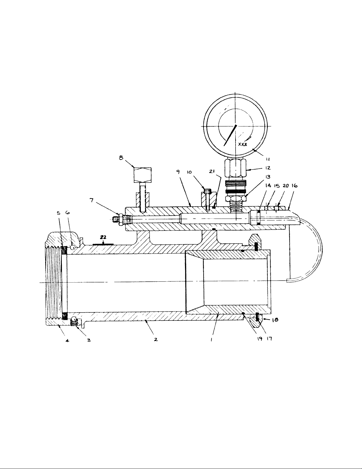
WATER FLOW TEST KIT
AKRON BRASS
STYLE 9015
PRECAUTIONS
1. Follow instructions in NFPA 1911, Acceptance and Service Test of Fire Department Pumping Apparatus, NFPA 291 Fire Flow
Testing and Marking of Hydrants or NFPA 1901 Automotive Fire Apparatus to promote safe and valid testing.
2. Mount the test kit nozzle securely. Never attempt to use the tester “hand-held”.
3. Direct the stream toward a cleared space that will remain clear throughout the test. This precaution is especially important when
testing hydrants along travelled streets and sidewalks.
4. Give the pressure gauge a “tug” after making quick connect to assure that the coupling has seated before pressurizing.
5. Use caution around the high velocity water streams and moving parts of the test kit.
6. Check all hose and apparatus connections before pressurization.
7. Do not attempt to interchange tips with stream running or pressurize a tip without lock ring secured in place.
8. Pitot blades are delicate and expensive. Replacement may require return of the entire kit for factory recalibration. Always flush
hydrant or pumper before inserting blade in stream. Do not drop blades or place them where they might be stepped on.
Table of contents
Other Akron Brass Test Equipment manuals
Popular Test Equipment manuals by other brands

Distek
Distek Evolution 6300 Operation manual

American DJ
American DJ Dr. DMX User instructions

MULTI MEASURING INSTRUMENTS CO.,LTD.
MULTI MEASURING INSTRUMENTS CO.,LTD. MIS-2D instruction manual

Viavi
Viavi ComXpert CX100 quick start guide

GW Instek
GW Instek GOS-6200 manual

ACS
ACS Alert J5 instruction manual