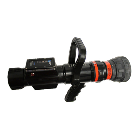
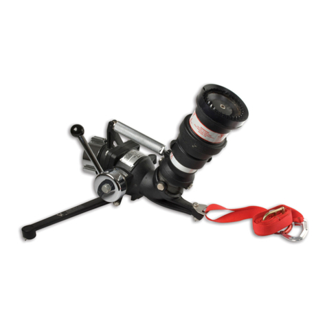
Akron 3578 STREAMMASTER Assembly instructions

TABLE OF CONTENTS
STYLE 3578 STREAMMASTER™
INSTALLATION, OPERATING, AND MAINTENANCE INSTRUCTIONS
(Version Available)
118026
English .................................................................1 - 19
Français ..............................................................20 - 38
Deutsch ..............................................................39 - 57
中文 (Chinese) ........................................................58 - 76
Español De América Latina (Spanish Latin America) .....................77 - 95


118026
STYLE 3578 STREAMMASTER™
INSTALLATION, OPERATING, AND MAINTENANCE INSTRUCTIONS
( Version Available)
The following is intended to provide the basic instructions for installation, operation and maintenance of the StreamMaster electric
monitor, and to assist in attaining the best possible performance from the unit. Read and understand these operating instructions
before use.
TOOLS REQUIRED
• Utility Knife • Medium flat screwdriver
• Medium Phillips screw driver • Small flat screwdriver
• Small Phillips screw driver • 1/2 inch hex head wrench
• Electrician’s pliers (multipurpose, stripping and crimping)
PRODUCT RATINGS
Maximum Motor Current Draw:
12 volt versions 14.0 amps each for elevation and rotation motors
3.0 amps for nozzle pattern motor
24 volt versions 7.5 amps each for elevation and rotation motors
1.5 amps for nozzle pattern motor
Normal Operating Current: (Depending on operating conditions–pressure, flow, etc.)
12 volt versions 3.0 to 10.0 amps each for elevation and rotation
0.7 amps for nozzle pattern motor
24 volt versions 2 - 5 amps each for elevation and rotation motors
0.4 amps for nozzle pattern motor
Minimum Voltage: (Truck engine must be operating for proper voltage requirement.)
All 12 volt motors: 11.5 volts while operating
All 24 volt motors: 23 volts while operating
Mass: 39 lbs. (17.7 kg)
Maximum Flow: 2000 gpm (7600 lpm)
Maximum Pressure: 200 psi (14 bar)
Noise Emission: 95 DL @ 1m with maximum flow
PRODUCT WARNINGS
WARNING: Charge the unit slowly. Rapid charging may cause a pressure surge that has the potential to cause an injury, or
damage the monitor.
WARNING: DO NOT stow or deploy the StreamMaster monitor while flowing. Pressing the stow or deploy buttons causes the
nozzle to move automatically and the water stream may cause damage to equipment or injury to personnel.
WARNING: Aim the unit in a safe direction before pumping water through it. (i.e. Away from power lines)

WARNING: Although the circuit board includes a water-resistant coating, it is important to keep water out of the control
box and logic box. Prolonged exposure to water will cause damage.
WARNING: When the cover of the control box or logic box is removed, check that the O-ring under the cover is intact and free
of dirt and debris.
WARNING: The StreamMaster monitor uses current limiting for both the monitor and nozzle. Use only appropriate Akron
Brass Company nozzles.
WARNING: Do not use the electric controls when the override cranks are being used or are in position for use.
WARNING: Make the connection of the vehicle and auxiliary battery the final step.
WARNING: Replace the identification tags if they should become worn or damaged.
WARNING: DO NOT exceed the maximum pressure or flow ratings of the monitor. Exceeding these ratings may lead to an
injury or may cause damage to the monitor.
WARNING: DO NOT install shutoffs on the outlet of the monitor. Shutoffs increase the potential for pressure surges due to
water hammer, which have the potential to cause an injury or damage to the monitor.
WARNING: The StreamMaster monitor, nozzle, logic box, control box, tether controller, and field adjustable stops are made for
optimal performance. Do not alter in any manner.
WARNING: The StreamMaster monitor was designed for use with the Akromatic nozzle. Use of any other nozzle could affect
the speed or operation of the unit and should be tested before being put into service.
WARNING: The StreamMaster monitor contains moving parts. Keep hand, finger and objects away from pinch
points (Figure 1).
WARNING: Disconnect power and disable flow before maintenance.
WARNING: Keep all personnel out of the Danger Zone (Figure 2), in front of the outlet of the monitor when the water source is
attached. Dangerous flow velocities can cause serious injury.
WARNING: Not designed for explosive environments.
GENERAL INSTRUCTIONS
• Review the instructions, wiring diagram, component layout and rotational stops diagram before installing this unit. This unit
operates on 12 volt DC or 24 volt DC depending on the unit chosen. All electrical current flows through the wires. The monitor
does not act as a ground. The wires from the control boxes can be cut to the length for the application plus 10 inches (See STEP 2).
Do not extend the wires from the logic box to the monitor.
• The optional auxiliary battery is used for power failures and to ensure that the proper voltage and current are maintained at the
logic box when using a smaller gauge wire (12 Awg) for the power leads (vehicle battery). If the optional auxiliary battery is used,
do not extend the auxiliary battery wires. This will ensure that the proper voltage and current are maintained at the monitor for it
to operate properly. The optional battery is automatically recharged by the truck electrical system through the positive
(auxiliary battery) and
ground connections on the circuit board (Figure 6). The vehicle battery connections must have power turned on whenever the
truck is running so that the battery can be recharged properly. If possible, connect the positive (vehicle battery) wire directly to the
main vehicle battery or main master switch. A diode in the logic box will prevent the optional auxiliary battery from feeding
current back into the main truck system.
• Not recommended for use in salt water applications.
• For firefighting by trained firefighters only.
• For use with water or standard fire fighting foams only. After use with foam, flush with fresh water.
• Do not use the StreamMaster nozzle as a forcible entry tool.
• Drain the StreamMaster monitor and nozzle after use to prevent “freeze damage”.
• Ensure that the thread in the nozzle swivel matches the thread on the StreamMaster outlet. Do not overtighten the nozzle onto
the Stream Master.
WARNING
2

3
MECHANICAL MONITOR ATTACHMENT
The Monitor is to be mounted on the waterway with eight 5/8 inch bolts and nuts of grade five minimum and suitable washers with a
minimum of six threads engagement. The front of the monitor in Figure 2 is considered to be point 4 and is above the identification
tag. The bolts must be tightened in a criss cross pattern progressively increasing tightening torque to a maximum of 100 foot
pound dry.
NOTE: Not recommended to mount on a raised flange or have a butterfly valve between the flanges.
This may cause damage to the monitor’s flange when tightening the bolts.
THE ROTATIONAL AND ELEVATION STOPS SET THE BOUNDARIES FOR THE AREA IN WHICH THE MONITOR IS ALLOWED TO
TRAVEL AND MEETS THE REQUIREMENTS OF THE NFPA. The upper row controls the right travel, and the lower row controls the left
travel. The angles for the rotational stops are with respect to the “reference direction” illustrated in Figure 2. The monitor is shipped
with the upper row stop at point 3 which stops the monitor at 90° right, clockwise and the lower row stop at point 5 which stops the
monitor at 90° left, counterclockwise. All other positions are achieved by switching the factory set stops and the plugs in the desired
stop location. Both the stops and the plugs have a 1/2 inch hex head. Refer to Figure 2 to determine which stop location is needed
for the desired right, clockwise or left, counterclockwise rotation. The elevation stop sets the upper and lower limits of the eleva-
tion. The monitor is shipped with the upper limit at 45° or 90° above horizontal (mounted vertically) and the lower limit at 45° below
horizontal to meet NFPA. All other vertical positions are achieved by switching plugs and stops to the desired locations as indicated
in Figure 4.
MECHANICAL ATTACHMENT OF CONTROLLER AND LOGIC BOX
A. CONTROLLER AND TETHER CONNECTOR ATTACHMENT
Pump panel cut out and mounting hole dimensions are given in Figure 3. The controller and tether connector should be installed
in the pump panel prior to electrical connection to the logic box.
B. LOGIC BOX ATTACHMENT
The StreamMaster logic box must be mounted close enough to the monitor to allow the 8 ft. monitor wiring harness sufficient
slack to allow the monitor to travel through its full range. The logic box overall dimensions and mounting hole dimensions are
given in Figure 5.
WARNING: Do not extend the monitor wiring harness.
ELECTRICAL INSTALLATION INSTRUCTIONS
A. CONTROLLER, JOYSTICK OR TETHER CONNECTOR ELECTRICAL ATTACHMENT
These instructions are for attaching the controller, joystick or the tether connector to the logic box. The controller, joystick and
tether connector are supplied with 8 ft. of cable.
STEP 1 If the control box includes an attached cable skip to STEP 6.
STEP 2 Determine the length of #20-7 cable needed, add 10 inches, then cut. For example, if a five foot length of cable
is needed, add 10 inches and cut the cable 5 foot 10 inches long.
STEP 3 Remove the cable grip nut and washer from the control box and put it on the cable with the threads facing the box. On
the same end of the cable remove 4 inches of the outer casing of the cable and strip back 3/8 inch from each of
the 7 wires.
STEP 4 Take the 7 ring terminals from the plastic bag and crimp them on the 7 wires. Remove the four control box cover screws
and set the control box cover aside. Thread the 7 wires through the cable grip attached to the control box and attach
them to the proper terminals. Tighten the cable grip nut and washer on the cable to
the cable grip on the control box to secure the cable. Reattach control box cover and
secure with the four screws
STRAIGHT
FOG LOWERLEFT
RAISERIGHT
WHT
WHITE
WHT
BRN
BLUE
WHITE
GREEN
RED
BLACK
YELLOW

4
STEP 5 Remove the cable grip nut from the plastic bag and put it on the other end of the cable with the threads facing
out. Remove 6 inches of the outer cover and strip back 3/8 inch from each of the 7 wires.
STEP 6 Remove the 6 logic box cover screws and set the logic box cover aside. Thread the 7 wires through the upper or
lower control hole in the logic box (see component layout, Figure 5). Thread the cable grip washer and cable
grip nutwith the threads facing the box on the cable. Pull enough cable through the cable grip to ensure a good fit.
Tighten the cable grip nut and attach the individual wires to the proper terminals (see wiring diagram Figure 6).
Reattach the logic box cover and secure with the 6 screws.
NOTE: The lower control and upper control wires must be attached to the correct terminals for the lower control
to over ride the upper control. The one attached to the Master terminal will have the overriding capabilities.
Adjust the DIP switch settings as needed. (Refer to the description below.)
B. DIP SWITCH SETTINGS
The DIP switches are located in the logic box on the circuit board.
The switches are factory set at:
Switch 1 - Allows the ability to use a 6-wire controller for the Stow controller instead of 10- wire.
UP - Enables the 6-wire Stow controller
DOWN - Disable the 6-wire Stow controller
Switch 2 - Allows the Stow and Deploy switch to be a momentary or a maintain switch.
UP - Requires JOG (maintain) to Stow or Deploy (No Learn mode if DIP 2 is ON)
DOWN - Momentary switch to start the Stow or Deploy sequence (factory set)
Switch 3 - Lowers the monitor during the Deploy sequence for 2.5 seconds.
UP - Deploys for 2.5 seconds (factory set)
DOWN - Will not Deploy the 2.5 seconds
Switch 4 - Lowers the monitor during the Deploy sequence for 3.75 seconds.
UP - Deploys for 3.75 seconds
DOWN - Will not Deploy 3.75 seconds (factory set)
Note: If Switch 3 and 4 are both ON the monitor will lower for 5 seconds during the Deploy sequence.
Switch 5 - Allows the nozzle to return to straight stream during the Stow sequence.
UP - Returns the nozzle to straight stream during the Stow sequence
DOWN - Leaves nozzle pattern set where last used (factory set)
Switch 6 - Stew Sequence. (See Notes on page 9, put definition here)
Switch 7 - Allows the user to choose between the Learned positions or the Default positions.
UP - Stow at the Learned position (factory set)
DOWN - Stow in the default position only
Switch 8 - Allows the user to turn the Learn mode ON or OFF
UP - Enables Learn mode programming (factory set)
DOWN - Disable the Learn mode, the user cannot reprogram a new setting
Notes: UP=Away from the bound, towards the "OPEN" position.
DOWN=Pushed DOWN towards the board.
Function is active when DIP Switch is in the "UP" position.
1 2 3 4 5 6 7 8
UP • • •
DOWN • • • • •

5
C. MONITOR WIRING HARNESS ATTACHMENT
These instructions are to attach the monitor wiring harness to the logic box.
STEP 7 Remove the cable grip nut from the logic box for the wiring harness cable. DO NOT REMOVE THE CABLE GRIP. Put the
cable grip nut on the wiring harness cable with the threads facing out. Put the cable through the correct logic box cable
grip (see componentl layout, Figure 5) so the cable grip nut will grab the outer cover of the cable. Tighten the cable grip
nut and attach the individual wires to the proper terminals (see wiring schematic Figure 6).
D. BATTERY ATTACHMENT
The battery connections should be the last connection made.
STEP 8 AUXILIARY BATTERY - Remove the logic box cable grip nut for the auxiliary battery and place it on the battery
(#16-3) cable with the threads facing out. Thread the cable through the cable grip nut until the cable grip will grab
the cable. Tighten the cable grip and attach the individual wires to the proper terminals (see wiring schematic Figure 6).
NOTE: Auxiliary Battery is not intended to operate the monitor.
STEP 9 VEHICLE BATTERY - Remove the logic box cable grip nut for the vehicle battery and place it on the battery cable
(#10-2 or #12-2 depending on length) with the threads facing out. Thread the cable through the cable grip until the
cable grip nut will grab the cable. Tighten the cable grip nut and attach the individual wires to the proper terminals
(see wiring schematic Figure 6). Reattach the logic box cover and secure with the 6 screws. NOTE: To supply enough
current to operate the monitor properly, adequate wire size is critical.
OPERATING INSTRUCTIONS
A. CONTROLLER OPERATION
The controller is used to control the monitor and nozzle.
1. To deploy the monitor for use: Lift the safety cover on the STOW/DEPLOY switch and push the toggle switch up and release.
Note: Some models may not be equipped with a deploy switch. The Deploy Function will only lower
the monitor. See DIP Switch 3 and 4.
2. To stow the monitor after use: Lift the safety cover on the STOW/DEPLOY switch and push the toggle switch down
and release.
Note: Some models may not be equipped with a deploy switch.
3. To change the horizontal monitor position toward the right or left: Press the proper toggle switch toward “RIGHT” or “LEFT”
respectively, as labeled on the controller, until the desired position is reached.
4. To change the vertical monitor nozzle position upward or downward: Press the proper toggle switch toward “RAISE” or
“LOWER” respectively, as labeled on the controller, until the desired position is reached.
5. To change the nozzle pattern toward the straight stream or fog position: Press the proper toggle switch toward “STRAIGHT”
or “FOG” respectively, as labeled on the controller, until the desired nozzle position is reached.
THE LOWER CONTROL BOX FUNCTIONS WILL OVERRIDE THE UPPER CONTROL BOX FUNCTIONS IN COMPLIANCE WITH THE
REQUIREMENTS OF THE NFPA STANDARD. NOTE: THE LOWER CONTROL AND UPPER CONTROL WIRES MUST BE ATTACHED TO
THE CORRECT TERMINALS FOR THE LOWER CONTROL (MASTER) TO OVERRIDE THE UPPER CONTROL (SLAVE). NONE OF THE
FUNCTIONS CAN BE CONTROLLED FROM THE UPPER CONTROL BOX WHEN ANY OF THE SWITCHES ON THE LOWER CONTROL
BOX ARE ACTIVATED.

6
B. EMERGENCY STOP DURING DEPLOY OR STOW
If it is necessary to immediately stop the StreamMaster monitor during the deploy or stow sequence, activate any switch on the
control panel and the unit will stop moving (E-Stop). To continue operation after an emergency stop, operate any switch or
press the Stow or Deploy switch to continue the sequence.
C. MANUAL OVERRIDE CONTROLS
The manual override control is to be used only when the power to the monitor is off. A override crank with a 1/4” hex drive is
provided and attached to the monitor for use on both the horizontal and vertical override controls. To use the manual override,
insert the hex drive end of the override crank into the hexagon shaped hole on the shaft end opposite the motor. Rotate the
override crank in the desired direction to aim the monitor.
WARNING: When the override crank is no longer in use, put it back in the storage position. Do not use the electric controls
when the override crank is being used or is in position for use.
D. LEARN MODE FOR STANDARD 10-wire Controller (Switch Operator Station)
The learn mode allows the operator to teach the monitor a new final position for the nozzle in the stowed position.
To learn a new stowed position:
1. Start with the monitor in a deployed position.
2. Press and hold the Stow button. The monitor will stow into the default stowed position. If at any point you release the Stow
button, you must start over.
3. When the monitor comes to a stop, continue holding the stow button and operate the up or down button to the desired
elevated position, then operate the left or right button to the desired rotation position.
4. Release the Stow button, this will be the new stowed position. Note: There is no learn mode for the Deploy Function. See
DIP Switch 3 and 4.
Introduction
E. LEARN MODE FOR SPECIAL 6-WIRE CONTROLLER (Switch Operator Station)
Introduction
The Six Wire Controller was developed to reduce wires and hence reduce slip rings on the turntable for an Aerial. The premise of
this is to reduce the lower controller wires for a Stow Controller from 10 wires to 7 or 6 wires (6 wires if the supply voltage comes
from a different source). This was done by removing the LED (1 wire) and using multiple signals to replace the Stow and Deploy signal
(2 wires). When the Stow button is activated, three signals are sent to the Logic Box (Fog, Stream, and Right). When the Deploy but-
ton is activated, Fog, Stream, and Left are sent to the Logic Box. The program in the Logic Box will recognize these signals as Stow or
Deploy when DIP Switch 1 is UP.
How to identify a “6-Wire” system
You have a “6-Wire” system if:
- DIP switch # 1 (in the Logic Box) has to be UP (away from board, towards the “OPEN” position) for
Stow, or Deploy to work.
- Stow (and /or Deploy) works, but there are no wires connected to TB1, terminals 7, 8, 21, or 22.
- Operator switch station does not have a red LED indicator lamp.
Part numbers: 35781002 (Surface Mount), and 35781003 (Flush Mount)
NOTE: The configuration of these two controllers is such that when you press the STOW switch, it will send out voltage on three
wires at the same time: FOG, STREAM, and RIGHT.
When you press the DEPLOY switch, it will send out voltage on three wires at the same time: FOG, STREAM, and LEFT.

7
Programming a new Stow position with a “6-Wire” system
When using a Six Wire Controller (Dip Switch 1 is UP), it will be necessary to temporarily borrow a switch function from the toggle
switch operator station or controller. For Learning a new Stow position, we will
temporarily use the FOG switch, or button, as a STOW switch.
1 - Turn power OFF.
2 - Disconnect the “Fog” wire (usually brown or tan) from TB1, terminal 1(or terminal 15 - usually best to use the
operator station that is closest to Monitor), and connect it to TB1, terminal 21 (Stow).
3 - Make sure that the DIP switches in the Logic Box are set as follows:
DIP Switch 1 = DOWN (Down - towards printed circuit board, “closed”)
DIP Switch 2 = DOWN (Down - towards printed circuit board, “closed”)
DIP Switch 7 = UP (Up - away from printed circuit board, “open”)
DIP Switch 8 = UP (Up - away from printed circuit board, “open”)
4 - Turn power ON
Make sure that the truck engine is running while going through the LEARN mode.
Truck voltage should be at normal running level.
5 - Momentarily press either one of the elevation or rotation switches to make sure that the monitor is in the
Deployed mode. LEDs inside the logic box should be ON solid. The unit will not enter the Learn mode for a
new stow position if it is not deployed, or if LEDs are flashing.
6 - Press and hold the FOG switch or button. The monitor will stow into the default stowed position. If at any
point you release the FOG switch, you must start over - go back to step 5.
Monitor should first move Left or Right looking for center of travel. (Magnet closes Horizontal position reed
switch at center of horizontal travel) IF it does not find the magnet / reed switch, it may reverse direction a
couple of times. LEDs inside Logic box will blink out code 3 if horizontal position magnet is not found at this time.
Monitor should then move up or down looking for Elevation magnet / reed switch activation, “telling” it where
it is at during elevation. (Should stop at factory default stow position for elevation) IF it does not find the
magnet / reed switch, it may reverse direction a couple of times. LEDs inside Logic box will blink out code 3
if the Elevation reed switch is not found at this time.
If the monitor times out, or an E-Stop condition occurs, then LEDs inside Logic box will blink out code 3.
Under normal conditions, the LEDs inside Logic box should be blinking out code 2 during stow operation.
7 - When the monitor comes to a stop, continue holding the FOG switch and operate the Raise or Lower
switches to the desired elevation position, then operate the Left or Right switch to the desired rotation
position.
8 - Release the FOG switch. This will be the new Stowed position, LEDs should stop flashing and turn off.
Note: There is no Learn mode for the Deploy Function. See DIP switch numbers 3 and 4.
9 - Set DIP Switch 8 = DOWN (Down - towards printed circuit board, “closed”) to lock the LEARN Mode.
10 - Set DIP Switch 1 = UP (Up - away from printed circuit board, “open”) to re-enable “6-Wire” operation.
11 - Turn power OFF.
12 - Disconnect the “Fog” wire, from TB1, terminal 21, and re-connect it where it was originally
(TB1, terminal 1 or 15). Unit should now be wired as it was before step number 2.
13 - Turn power back ON, and test monitor functions.

8
Trouble-shooting
1 - Will not turn off LEDs or Cab indicator light after monitor appears to have completed a STOW cycle.
Monitor stops moving after a stow command, and looks like it is stowed, but the LEDs on the Logic Board go back to being on solid,
and the relay contacts at TB3, terminals 6,7,and 8 do not change state.
Note: The Stow Function will not operate properly when the upper outlet angle is set to 30°, see page 16.
Reason: Stow cycle is being interrupted (stopped) by a mechanical stop before the logic box has completed the timing cycles for the
stow movements.
Go through the LEARN procedure again, and try teaching a new stow position where the elevation, and / or rotation positions are
not so close to the mechanical stops.
Example:
On an aerial, where the 3578 is mounted under the ladder, the desired stow position may have the elevation set all the way up so
that the nozzle is right up under the ladder. This setting may be too close to the mechanical stop. Try “Learning” a new stow position
where the nozzle is slightly lower than before.
Make sure that the truck engine is running while going through the LEARN mode.
Truck voltage should be at normal running level.
2 - STOW problems / Will not learn a new STOW position
Note: Monitor must have “STOW” harness and reed switches on monitor for stow feature to work.
The logic box LEDs will ALSO blink out code 3 if the magnets are not “seen” by the reed switches during the stow sequence. A
problem with either rotation or elevation will cause the LEDs to blink out code 3 after the monitor has tried a couple of times to
locate the magnets. There is one magnet per axis, about middle of travel on each axis.
The reed switches, magnets, and wiring can be checked by using a voltmeter. TB3 terminal 27 should have about 7 to 8 volts with
respect to ground when the elevation reed switch and its magnet are lined up (facing each other), otherwise should be 0 volts. While
measuring voltage, move the wiring harness around to ensure that it does not have a broken wire, or an intermittent condition.
TB3 terminal 26 should have about 7 to 8 volts with respect to ground when the rotation reed switch and its magnet are lined up
(facing each other), otherwise should be 0 volts. While measuring voltage, move the wiring harness around to ensure that it does not
have a broken wire, or an intermittent condition.
Note: TB3 terminal 28 sends power (12.6VDC) out to the switches. When a reed switch closes, it sends the voltage back to the logic
box through a 1000 ohm resistor that is in the wiring harness (inside the main potting box mounted to the base of the monitor).
Since there is a 1500 ohm resistor at the input of the logic box, the voltage to TB3-26, and TB3-27 is divided down to about 7.56V.
If you have 12 volts at TB3 terminal 28, and you measure zero, or 12V at terminals TB3-26, or TB3-27 when the reed switches are
closed, then you have a defective harness or a defective logic board. Zero volts with a reed switch activated is most likely to be a
broken wire or connection in the harness. 12 volts is most likely to be a defective logic board.
With power OFF, to the Logic Box, you can also use the continuity test setting of your multimeter to check the reed switches, and
harness wiring. The reed switches should close (show continuity, zero ohms) when a magnet is placed in front of them. The wiring
harness with the reed switches closed should show about 1000 ohms. While measuring continuity, move the wiring harness around
to ensure that it does not have a broken wire, or an intermittent condition.

9
Notes:
Some applications use DIP Switch 6 on the printed circuit board.
Normally, DIP switch 6 is set DOWN (Down - towards printed circuit board, “closed”). During stow, the monitor will move Left/Right,
then Up/Down until it finds the default home position. Then it will move Up/Down, and Left/Right until it finds the Learned
Stowed position.
If DIP Switch 6 is set UP (Up - away from printed circuit board, “open”), During stow, the monitor will move Left/Right, then Up/
Down until it finds the default home position. Then it will move Left/Right, and Up/Down until it finds the Learned Stowed posi-
tion. If the Learned Stowed position is set too high, the monitor may only go to the Learned position for rotation (Left/Right)
This was done for certain applications where the mounting and / or the weight of the nozzle was an issue.
Pattern (Fog / Stream) does not have a “Learned” stow position. You can, however set DIP switch 5 for one of two options:
DIP Switch 5 = UP (Up - away from printed circuit board, “open”) Returns the nozzle to straight stream during the Stow sequence.
DIP Switch 5 = DOWN (Down - towards printed circuit board, “closed”) Leaves the nozzle pattern set where last used
(factory default setting).
With DIP switch 7 in the DOWN position (Down - towards printed circuit board, “closed”), the monitor will stow in the default posi-
tion, and both reed switches should be closed (reed switches and magnets are lined up, facing each other). TB3, terminals 26 and 27
should have 7 to 8 volts with respect to ground.

2 3/4 2 29/32
5 1/8 5 17/32 5 3/4 9 7/323/4
8 1/16
16 1/4
31/8 NH
Thread
6 1/8
90°
45°
21 3/16
12 3/4
15 1/2
21 3/16
4” 150° Flange
Dimensional
Specifications
Rotation Sensor
Elevation
Sensor
Range+90° TO -45°
WARNING
WARNING
10
Figure 1
F. FAULT CODES
Your StreamMaster monitor comes with built in diagnostic tools. On the controller for stow is a small
LED indicator. The primary function of the LED indicator is to indicate whether the monitor is stowed or
deployed. The LED indicator also functions as a Fault Indicator.
Deployed: The light will repeatedly flash twice as the unit is deploying. When the fully deployed position is reached the light
will stop flashing and remain on.
NOTE: As soon as the deploy sequence begins, the light in the cab will turn on.
Stowed: When the fully stowed position is reached the LED indicator will go out.
NOTE: The light in the cab will also go out when fully stowed.
Fault Code 1: Fault code 1 is represented when the light flashes continually. If the EEPROM on the circuit board is faulty, Fault
1 will occur.
Correction: The circuit board must be replaced
Fault Code 2: Fault code 2 is normal during the deploy sequence and is represented when the light repeatedly flashes twice.
Code 2 is not a fault, but occurs when the deploy button is pressed and automatically ends when the fully
deployed position is reached. Operation of any switch while flashing twice will cause the monitor to go
into E-stop
mode. (See Fault Code 3)
Fault Code 3: Fault code 3 is represented when the light repeatedly flashes 3 times. This fault code indicates an emergency stop
(E-stops) occurred during stow or deploy. If any switch is pushed during the stow or deploy sequence all movement
will stop and Fault 3 will flash.
Correction: Operate any switch or press the Stow or Deploy switch to continue the sequence.
Fault Code 4: Fault code 4 is represented when the light repeatedly flashes 4 times. If the Deploy or Stow switch is pushed and
the monitor is prevented from rotating. Fault 4 will occur.
Correction: Check for an obstruction by the monitor. Remove the obstruction. Operate any switch or press the Stow or Deploy
switch to continue the sequence.
Fault Code 5: Fault code 5 is represented when the light repeatedly flashes 5 times. If the Stow or Deploy switch is pushed and
the monitor is prevented from elevating, Fault 5 will occur.
Correction: Check for an obstruction by the monitor. Remove the obstruction and operate any switch or press the Stow or
Deploy switch to continue the sequence.

11
MAINTENANCE INSTRUCTIONS
Your StreamMaster monitor and nozzle should be inspected prior to and after each use to ensure it is in good operating condition.
Periodically, an unanticipated incident occurs where the unit is misused in a manner that is inconsistent with standard operating
practices. A partial list of potential misuses includes:
• Operating above the maximum rated pressure or flow.
• Prolonged exposure to temperatures above 130°F, or below -25°F.
• Operating in a corrosive environment.
• Having the StreamMaster nozzle hit a fixed object during operation or transportation.
• Any other misuse that might be unique to your specific environment.
Also, there are many “tell tale” signs that indicate repair is in order, such as:
• Controls that are either inoperable or difficult to operate.
• Excessive wear
• Poor discharge performance
• Water leaks.
If any of the above situations are encountered, the StreamMaster monitor should be taken out of service, repaired, and tested by a
qualified technician before placing back in service.
MOTOR REPLACEMENT
To replace either the horizontal or vertical rotational motors:
1. Disconnect Power from the unit.
2. Loosen and remove the four socket screws (Item 4 on the Parts List) from the gearbox housing (52).
3. Slowly remove the motor assembly (59) and gearbox housing (52) from the unit.
IMPORTANT: Make sure the internal gear, (Item 47 on the Parts List), remains in place, (hold with a screwdriver), to avoid
gear alignment problems.
4. Loosen and remove the four socket head capscrews (51) from the inside of the gearbox housing that hold the housing and the
motor assembly together.
5. Remove gearbox housing (52) from the motor assembly (59).
6. Replace both o-ring seals (50 & 53) on the gearbox housing (52).
7. Attach the new motor assembly (59) to the gearbox housing (52) making sure all four screws (51) are tight.
8. Install the motor and gearbox housing assembly to the unit making sure all four socket screws are tight. It may be necessary to
rotate the motor slightly to get the motor gear to line up with the gears inside the gearbox.
9. Restore power to the unit.
10. Test the operation of the unit.
Call Akron Brass Customer Service Department if any problems are encountered.

CW / CCW 1 2 3 4 5 6 7 8 NO STOP
1 78 / 168 78 / 213 78 / 258 45 / 270 0 / 270 78 / 33 67.5 / 270 22.5 / 270 78 / 270
3 180 / 0 135 / 0 90 / 0 45 / 0 0 / 0 315 / 0 67.5 / 0 22.5 / 0 348 / 0
4 180 / 45 135 / 45 90 / 45 45 / 45 0 / 45 303 / 33 67.5 / 45 22.5 / 45 303 / 45
5 180 / 90 135 / 90 90/90 45 / 90 0 / 90 258 / 33 67.5 / 90 258 / 90 258/90
6 180 / 135 135 / 135 90 / 135 45 / 135 0 /135 213 / 33 67.5 / 135 22.5 / 135 213/135
7 180 / 22.5 135 / 22.5 90 / 22.5 45 / 22.5 0 / 22.5 315 / 22.5 67.5 / 22.5 22.5 / 22.5 325.5/22.5
8 180 / 67.5 135 / 67.5 90 / 67.5 45 / 67.5 0 / 67.5 280.5 / 33 67.5 / 67.5 22.5 / 67.5 280.5 /
67.5
NO STOP 180 / 168 135 / 213 90 / 258 45 / 303 0 / 348 315 / 33 67.5 / 280.5 22.5 / 325.5 N /A
12
Figure 2
STREAMMASTER
ROTATION FOR EACH STOP COMBINATION
Upper Row
LOWER ROW
Factory Set Stops
NOTE: There is no lower row for point 2 due to the location of the wiring harness.
Each possible combination is listed and a maximum of 348 degrees can be achieved for total rotation. The factory will set
the stops at Lower Row point 5 and Upper Row point 3. This will give a rotation of 90 degrees clockwise (CW) and 90 de-
grees counterclockwise (CCW) for a total rotation of 180 degrees. Factory Set Stops
NOTE: There is no lower row for point 2 due to the location of the wiring harness.

13
Figure 3
2
6
R 1/4
IN TRUCK PANEL
ROUGH OPENING
#10-24 UNC TAPPED HOLE (TYP 4)
MAX AT CORNERS
5.000
3.250
5.500
3.750
4 1/4
6
TRUCK PANEL CUT OUT DIMENSIONS
READ OPERATING INSTRUCTIONS BEFORE USE
FOG LEFT LOWER
RAISERIGHT
SS
BRASS COMPANY
PANEL MOUNT CONTROLLER

14
Figure 3A
PANEL MOUNT CONTROLLER FOR STOW
TRUCK PANEL CUTOUT DIMENSIONS
96"
4 1/4
3 3/4
8
1/4 RAD MAX AT CORNERS
CLEARANCE FOR FACEPLATE
ROUGH OPENING IN TRUCK PANEL
#10-24 UNC TAPPED HOLE (TYP 4)
STRIP BACK 3/8 " (TYP 10)
6"
3 1/4
7 1/2
2 1/2
STOW
DEPLOY
DeckMaster
FOG LEFT LOWER
RAISERIGHT
SS
WARNING
READ OPERATING INSTRUCTIONS BEFORE USE
WHILE FLOWING WATER
DO NOT DEPRESS STOW OR DEPLOY
7

15
Figure 3B
(DOWN)
(UP)
FOG
SQUAR
E
5.500
8.338
5.275
(RIGHT)
(LEFT)
TYP 4
CLEARANCE FOR CONNECTOR FLANGE
1 9/32
1 9/32
`1 HOLE
PANEL MOUNTING DIMENSIONS
#4-40 UNC TAPPED HOLE
.969
.969
96 INCHES
6
JOYSTICK
TETHER CONNECTOR

16
Figure 4
The elevation stop position and their corresponding stop/plug configurations are shown in the table below. The hole location
for the plug/stop is referred to by an angle from the horizontal. The outlet angle is the angle trajectory (from horizontal) the
water will flow from the StreamMaster unit.
ELEVATION STOPS
Note that the permanent stop must remain installed. If this stop is removed, the outlet will go past vertical and the gear will
run out of travel.
There are six options for the customer to use. This is achieved with 3 plugs, 1 permanent stop, and 2 stops provided
(the unit will be assembled with the permanent stop in 0° location, 1 stop in the -45°, and plugs in the remaining
15° and -60° locations).
The parts kit will contain 1 stop and 1 plug.
P=PLUG S=STOP PS=PERMANENT STOP
Factory Set Stops
HOLE LOCATION Lower Upper
Outlet Outlet
Angle Angle
15° 0° -45° -60°
P PS S P -45° 45°
P PS P S -45° 30°*
S PS P P -30° 90°
P PS P P -45° 90°
S PS P S -30° 30°*
S PS S P -30° 45°
P
PS
S
P
15°
-60°
-45°
*-The Stow Function will
not operate properly when
the upper outlet angle is set
to 30°.

17
Figure 5
8.312
5 3/4
4.625
2 11/32
8 3/4
READ OPERATING INSTRUCTIONS BEFORE USE
Akron Brass
SS
LOWERLEFTFOG
RAISERIGHT
Akron Brass
SS
LOWERLEFTFOG
RAISERIGHT
DeckMaster
FOG LEFT LOWER
RAISERIGHT
SS
WARNING
READ OPERATING INSTRUCTIONS BEFORE USE
STOW
DEPLOY
WHILE FLOWING WATER
DO NOT DEPRESS STOW OR DEPLOY
Logic Box
Vihicle Battery
Cable Entrance
(10-2 or 12-2
20-7 or 20-10 Cable
Upper Control Box
(Option)
Joystick and Harness (not sealed)
(Option)
Elevation
Motor Cable
Rotation
Motor Cable
Wiring Harness
(Attached to Montor)
Pattern Motor
Cable
Lower Control Box
Surface or Panel Mount
16-6 or 16-10 Cable
Aux. Battery
(Option)
16-2 Cable
Optional
Configuration
Controller Symbols
Straight Stream
Fog
Right Left
Up Down
ELECTRICAL
COMPNENT
LAYOUT

18
Figure 6
TB2
TB3 TB1
20-7 OR 20-10 CABLE
16-6 OR 16-10 CABLE
20-7 OR 20-10 CABLE
TO MONITOR
+12/24 VOLT
+12/24 VOLT
+12/24 VOLT
+12/24 VOLT AUX BATTERY (OPTIONAL)
+12/24 VOLT VEHICLE BATTERY
TO CONTROL BOX OR JOYSTICK
GROUND
GROUND
IND LIGHT
IND LIGHT
MASTER
SLAVE
TO VEHICLE BATTERY
WHT
TAN
YEL
GRN
BLU
RED
BLK
ORG
PUR
GRY
WHT
RIGHT MOTOR
UP MOTOR
– VEHICLE GROUND
AUX GROUND
ORG
BLU
BLK
RED
GRN
WHT
LED2
LED1
FOG
STREAM
UP
DOWN
LEFT
RIGHT
STOW
DEPLOY
TAN
YEL
GRN
BLU
RED
BLK
ORG
PUR
GRY
STREAM
UP
DOWN
LEFT
RIGHT
STOW
DEPLOY
SS MOTOR
FOG MOTOR
DOWN MOTOR
LEFT MOTOR
CABLE TO CAB LIGHT CIRCUIT
contacts rated 1 amp at 24 vdc max.
Note: IND LITE is a set of SPDT
the IND LITE
Customer must supply power to
DeployedStow
UP = ACTIVE
DIP FUNCTIONS
Deploy Timer 4 secs
Deploy Timer 2 secs
Jog To Stow
Six Wire Stow
Use the Learned Positions
Enable LEARN Mode
Stow Sequence
Go to SS during Stow
8
1
DOWN
DOWN
DOWN
DOWN
DOWN
UP
UP
UP
Factory Settings
876876
4
1
Black
Green
White
28
2815
15
14
14
1
1
28
27
26
25
24
23
22
21
20
19
18
17
16
15
14
13
12
11
10
9
8
7
6
5
4
3
2
1
14
13
12
11
10
9
8
7
6
5
4
3
2
1
28
27
26
25
24
23
22
21
20
19
18
17
16
15
+12/24 VOLT
SLAVE
MASTER
RED/BLK
GRN/BLK
WHT/BLK
LIM ROT
LIM ELEV
FOG
Other manuals for 3578 STREAMMASTER
2
Table of contents
Languages:
Other Akron Measuring Instrument manuals
Popular Measuring Instrument manuals by other brands

Hanna
Hanna HI 96785C instruction manual

Hanna Instruments
Hanna Instruments HI84529 instruction manual

Endress+Hauser
Endress+Hauser Proline Promass A 300 PROFINET operating instructions

HBK
HBK PAD4002A operating manual

Molecular Devices
Molecular Devices Digidata 1550B user guide

ziltek
ziltek REMSCAN Quick start instructions