manuals.online logo
Brands
  1. Home
  2. •
  3. Brands
  4. •
  5. Aksa
  6. •
  7. Inverter
  8. •
  9. Aksa ALP 8 User manual

Aksa ALP 8 User manual

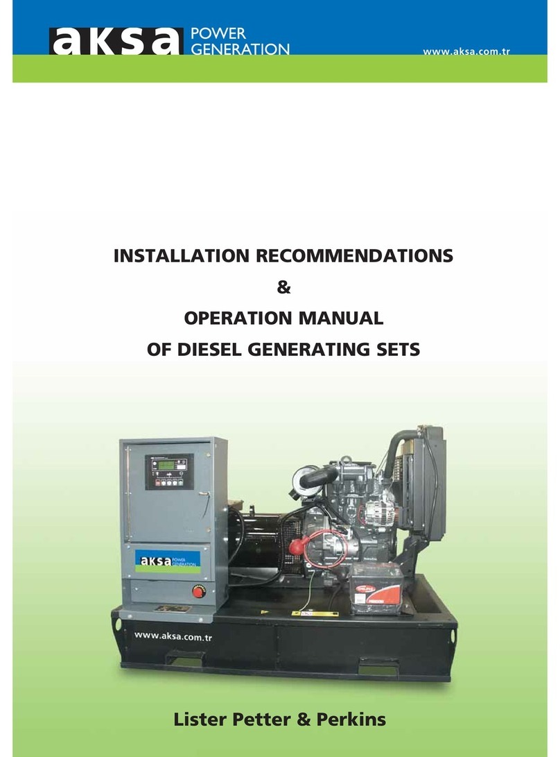
INSTALLATION RECOMMENDATIONS
&
OPERATION MANUAL
OF DIESEL GENERATING SETS
www.aksa.com.tr
Lister Petter & Perkins
All manuals and user guides at all-guides.com
all-guides.com
Dear Aksa Generating Set Operator
First of all, we would like to thank you for your choice of Aksa Power
Generator.
This operating and maintenance manual is designed and developed to
make you familiar with the generator system.
This manual gives general information about mounting, operation and
maintenance of the generating set. Tables and diagrams are also available
outlining your generating set.
ever operate, maintain or repair your generating set without taking
general safety precautions.
All manuals and user guides at all-guides.com
I
CONTENTS
INTRODUCTION.........................................................................................
SAFETY .......................................................................................................
2.1 General ...........................................................................................
2.2 Installation, Handling and Towing .........................................................
2.3 Fire and Explosion ..................................................................................
2.4 Mechanical ..........................................................................................
2.5 Chemical ................................................................................................
2.6 oise .....................................................................................................
2.7 Electrical ................................................................................................
2.8 First aid For Electric Shock ...................................................................................
GENERAL DESCRIPTION.....................................................................................
3.1 Generating Set Description and Identification......................................
3.2 Diesel Engine .........................................................................................
3.3 Engine Electrical System .......................................................................
3.4 Cooling System ......................................................................................
3.5 Alternator ..........................................................................................
3.6 Fuel Tank and Baseframe ......................................................................
3.7 Vibration Isolation .................................................................................
3.8 Silencer and Exhaust System ...........................................................
3.9 Control System ..................................................................................
INSTALLATION, HANDLING AND STORAGE...........................................
4.1 General .................................................................................................
4.2 Canopies ......................................................................................
4.3 Location ................................................................................................
4.4 Moving the Generating Set ................................................................
4.5 Foundations Vibration Isolation ...................................................
4.6 Combustion Air Inlet ...........................................................................
4.7 Cooling and Ventilation ......................................................................
4.8 Exhaust ..................................................................................................
4.9 Fuel System ..........................................................................................
4.9.1 Day Tank ....................................................................................
4.9.2 Bulk Storage Tank .......................................................................
4.9.3 Fuel Lines ..........................................................................................
4.10 Lubrication Oil ...................................................................................
4.10.1 Oil Performance Properties .......................................................
4.10.2 Recommended Oil Properties for Perkins Diesel Engines........
4.10.3 Lubrication Oil Recommendations by Lister Petter
4.11 Batteries ..............................................................................................................
4.11.1 Maintenance Batteries ..........................................................................
4.11.1.1 First Filling of Acid Water to The Battery ....................................
4.11.1.2 Battery Maintenance .....................................................................
4.11.1.3 Testing the Battery.............................................................................................
4.11.1.4 Hydrometer Test ........................................................................................
4.11.2 Maintenance Free Batteries..........................................................................
4.12 Electrical Connection .......................................................................................
4.12.1 Cabling ...................................................................................................
4.12.2 Protection ......................................................................................................
4.12.3 Loading ................................................................................................................
4.12.4 Power Factor .......................................................................................................
4.12.5 Grounding / Earthing Requirements ............................................
4.12.6 Alternator Reconnection ...... .............................................................
4.12.7 Parallel Running .....................................................................................
4.12.8 Insulation Test ........................................................................................
4.13 Acoustic Silencing................................................................................
4.13.1 Exhausts Silencers .....................................................................
4.13.2 Canopies ..........................................................................................................
4.13.3 Other Sound Attenuation...................................................................
4.14 Engine Jacket Water Heater.........................................................
1.
2.
3.
4.
1
2
2
2
2
3
3
3
3
4
6
6
6
6
6
6
6
6
6
6
8
8
8
8
8
9
9
9
10
13
13
13
13
17
17
17
17
17
17
17
18
18
18
18
18
18
18
19
19
21
21
21
21
21
21
21
21
21
All manuals and user guides at all-guides.com
II
4.15 Towing (Mobile Generating Sets)..........................................
4.15.1 Preparing to Low ........................................................................
4.15.2 Towing ....................................................................................
4.15.3 Parking .....................................................................................
4.16 Storage.....................................................................................
4.16.1 Engine Storage .........................................................................
4.16.2 Alternator Storage ...................................................................
4.16.3 Battery Storage ...................................................................
GENERATING SET MAINTENANCE ...............................................................
GENERAL PRECATIONS AND CONTROLS WHICH MUST BE DONE
BEFORE STARTING UP THE GENERATING SET ........................................
GENERATING SET CONTROL SYSTEMS .............................................................
7.1 Starting with ME 40 Manual Control Panel ...................................................................
7.3 Starting With P 300 Autostart Control Panel ....................................................
7.3.1 Manual Operation .......................................................................................................
7.3.2 Automatic Mode of Operation .........................................................................
7.3.3 Test Mode of Operation .........................................................................
7.4 Starting With P 2010 Autostart Control Panel ....................................................
7.4.1 Manual Operation .......................................................................................................
7.4.2 Automatic Mode of Operation .........................................................................
7.5 Starting with P 2020 Automatic Control Panel .....................................................
7.5.1 Manual Operation ..........................................................................................
7.5.2 Automatic Mode of Operation .....................................................................
7.5.3 Test Operation ............................................................................................................
GENERAL PRECATIONS AND CONTROL WHICH MUST BE DONE
AFTER STARTING UP THE GENSET ...........................................................................
STOPPING THE GENERATING SETS .......................................................................
9.1 At Manual Models ........................................................................................
9.2 At Automatic Models ..................................................................................................
GENERATING SET CONTROL SYSTEMS ...............................................
10.1 Control Panels ..................................................................................................
10.2 Manual Control System ME40................................................................
10.2.1 DSE 701 Module Features ...............................................................
10.2.2 DSE 701 Module Emergency Leds ...............................................................
10.3 Automatic Control System P 300 Panel Specifications .................
10.3.1 DSE 720 Module Features ...........................................................
10.4 Automatic Control System P 2020 Panel Specification .................
10.4.1 DSE 5220 Module Features ................................................................
10.5 Autostart Control System P 2010 Panel Specification .................
10.5.1 DSE 5210 Module Features ..............................................................................
10.6. Panel Equipments .....................................................................................
10.6.1 AC Voltmeter ......................................................................................................
10.6.2 Voltmeter Selector Switch .....................................................................................
10.6.3 AC Ampermeter ......................................................................................................
10.5.4 Frequencymeter ......................................................................................................
10.6.5 Hoursrunmeter ......................................................................................................
10.6.6 Water Temperature Gauge ....................................................................
10.6.7 Oil Pressure Gauge .................................................................................................
10.6.8 Emergency Stop Pushbutton .............................................................................
THE PLACEMENT AND INSTULATION OF TRANSFER SWITCH .....
DSE 53 MODEL FULL AUTOMATIC TRANSFER SWITCH CONTROL
SYSTEM ....................................................................................................................
12.1 Automatic Mode of Operation ..........................................................
12.2 Manual Restore Mode of Operation ..........................................................
12.3 Manual Operation...................................................................................................
12.4 Indications ....................................................................................................................
ALTERNATOR TROUBLESHOOTING................................................................
ENGINE TROBLESHOOTING...........................................................................
5.
6.
7.
8.
9.
1 .
11.
12.
13.
14.
21
21
21
21
21
21
22
22
22
22
22
22
23
23
23
23
23
24
24
24
25
25
26
26
26
26
27
27
27
27
27
27
27
27
28
28
29
29
29
29
29
29
30
30
30
30
30
32
33
33
33
33
33
34
35
All manuals and user guides at all-guides.com
1. INTRODUCTION
1
Aksa Generating set is designed to be
commissioned, when delivered, as soon as the
necessary cooling water, antifreeze, fuel,
lubrication oil and fully charged battery are
provided.
With its long years of experience, Aksa
manufactures efficient, reliable and quality
generating set.
This operating and maintenance manual is
prepared to assist the operator in operation and
maintenance of the generating set. Observing
the advices and rules in this manual will ensure
that the generating set operates in maximum
performance and efficiency for a long time.
Care should be taken to perform more frequent
maintenance in dirty and dusty environments in
order to keep the generating set in good working
condition.
ecessary adjustments and repairs should be
made only by authorized and qualified persons.
Each generating set has a model and a serial
number indicated on a label on the base frame.
This plate also indicates the manufacturing date,
voltage, current, power in kVA and kW,
frequency, power factor and weight of the
generating set. These datas are necessary in
spare part orders, for warranty validity and for
service calls.
Figure 1.1 AKSA Generating set label
Gülbahar Cad. 1. Sokak 34212 Günesli Istanbul / Türkiye
Tel: + 0 212 478 66 66 (pbx) Fax: + 0 212 657 55 16
e-mail: [email protected] www.aksa.com.tr
PHASE
Cosj
RPM
STANDBY kVA.
STANDBY A.
DIMENSIONS
FUEL TANK CAPACITY L.
LWH
TS EN 9001 : 000
CERTIFICATION NO: 16197
CERTIFICATION NO: 16197/1
0 5-4
All manuals and user guides at all-guides.com
Engine exhaust emissions are hazardous to
personnel. The engine exhaust for all indoor
generating sets must be piped outdoors via leak-
free piping in compliance with relevant Codes,
Standards and other requirements. Ensure that
hot exhaust silencers and piping are clear of
combustible material and are guarded for
personnel protection per safety requirements.
Ensure that fumes from the exhaust
outlet will not be a hazard.
ever lift the generating set by
attaching to the engine or alternator
lifting lugs, instead use the lifting
points on the baseframe or canopy.
Ensure that the lifting rigging and
supporting structure is in good condition and
has a capacity suitable for the load.
Keep all personnel away from the generating set
when it is suspended.
2
2. SAFETY
2.1 GENERAL
The generating set is designed to be safe when
used in the correct manner. However
responsibility for safety rests with the personnel
who install, use and maintain the set. If the
following safety precautions are followed, the
possibility of accidents will be minimized. Before
performing any procedure or operating
technique, it is up to the user to ensure that it
is safe. The generating set should only be
operated by personnel who are authorized and
trained.
!
!
!
WARNING
Read and understand all safety precautions and
warnings before operating or performing
maintenance on the generating set.
Failure to follow the instructions, procedures, and
safety precautions in this manual may increase the
possibity of accidents and injuries.
Do not attempt to operate the generating set with
a known unsafe condition.
If the generating set is unsafe, put danger notices
and disconnect the battery negative (-) lead so that
it cannot be started until the condition is corrected.
Disconnect the battery negative (-) lead prior to
attempting any repairs or cleaning inside the
enclosure.
Install and operate this generating set only in full
compliance with relevant ational, Local, or Federal
Codes, Standards or other requirements.
!
!
!
Fuel and fumes associated with generating sets
can be flammable and potentially explosive.
Proper care in handling these materials can
dramatically limit the risk of fire or explosion.
However, safety dictates that fully charged BC
and ABC fire extinguishers are kept on hand.
Personnel must know how to operate them.
2.3 FIRE AND EXPLOSION
!
!
Chapter 4 of this manuel covers procedures for
installation, handling, and towing of generating
sets. That chapter should be read before installing,
moving and lifting the generating set or towing
a mobile set. The following safety precautions
should be noted:
2.2 INSTALLATION,
HANDLING AND TOWING
WARNING
Make electrical connections in compliance with
relevant Electrical Codes, Standards or other
requirements. This includes requirements for
grounding and ground/earth faults.
For stationary generating sets with remote fuel
storage systems, make sure such systems are
installed in compliance with relevant Codes,
Standards or other requirements.
!
!
!
!
!
!
!
!
WARNING
Ensure that the generating set room is properly
ventilated.
Keep the room, the floor and the generating set
clean. When spills of fuel, oil, battery electrolyte
or coolant occur, they should be cleaned up
immediately.
ever store flammable liquids near the engine.
Do not smoke or allow sparks, flames or other
sources of ignition around fuel
or batteries. Fuel vapours are
explosive. Hydrogen gas
generated by charging batteries
is also explosive.
!
All manuals and user guides at all-guides.com
all-guides.com
WARNING
Do not attempt to operate the generating set
with the safety guards removed. While the
generating set is running do not attempt to reach
under or around the guards to do maintenance
or for any other reason.
Keep hands, arms, long hair, loose clothing and
jewellery away from
pulleys, belts and other
moving parts.
Attention: Some moving
parts can not be seen
clearly when the set is
running.
If equipped keep access
doors on enclosures
closed and locked when
not required to be open.
Avoid contact with hot
oil, hot coolant, hot
exhaust gases, hot surfaces and sharp edges and
corners.
Wear protective clothing including gloves and
hat when working around
the generating set.
Do not remove the
radiator filler cap until the
coolant has cooled. Then
loosen the cap slowly to
relieve any excess pressure before removing the
cap completely.
Turn off or disconnect the power to the battery
chargen before making or breaking connections
with the battery.
To avoiding arcing keep grounded conductive
objects (such as tools) away from exposed live
electrical parts (such as terminals). Sparks and
arcing might ignite fuel or vapours.
Avoid refiling the fuel tank while the engine is
running.
Do not attempt to operate
the generating set with any
known leaks in the fuel
system.
WARNING
Do not swallow or allow skin contact with fuel,
oil, coolant, lubricants or battery electrolyte. If
swallowed, seek medical treatment immediately.
Do not induce vomiting if fuel is swallowed. For
skin contact, wash with soap and water.
Do not wear clothing that
has been contaminated by
fuel or lube oil.
Wear an acid resistant apron
and face shield or goggles
when servicing the battery.
If electrolyte is spilled on
skin or clothing, flush immediately with large
quantities of water.
3
!
Fuels, oils, coolants, lubricants and battery
electrolyte used in this generating set are typical
of the industry. However, they can be hazardous
to personnel if not treated properly.
!
!
2.6 NOISE
!
!
!
!
2.4 MECHANICAL
The generating set is designed with guards for
protection from moving parts. Care must still
be taken to protect personnel and equipment
from other mechanical hazards when working
around the generating set.
!
!
!
!
!
2.5 CHEMICAL
!
Generating sets that are not equipped with sound
attenuating enclosures can produce noise levels
in excess of 105 dBA. Prolonged exposure to
noise levels above 85 dBA is hazardous to hearing.
WARNING
Ear protection must be
worn when operating or
working around an operating
generating set
!
2.7 ELECTRICAL
Safe and efficient operation of electrical
equipment can be achieved only if the equipment
is correctly installed, operated and maintained.
WARNING
The generating set must be connected to the
load only by trained and qualified electricians
who are authorized to do so, and in compliance
with relevant Electrical Codes, Standards and
other requlations.
Ensure that the generating set, including a mobile
set is effectively grounded/earthed in accordance
with all relevant regulations priorts operation.
!
!
!
!
All manuals and user guides at all-guides.com
Tilt the victims head back
and lift the chin upwards.
Remove objects from the
mouth or throat (including
false teeth, tobacco, or
chewing gum).
Check that the victim is
breathing by looking, listening and feeling for the
breath.
Check for pulse in the
victims neck.
Pinch the victims nose firmly.
Take a deep breath and seal your lips around
the victims lips.
Blow slowly into the mouth
watching for the chest to
rise. Let the chest fall
completely. Give breaths at
a rate of 10 per minute.
If the victim must be left to
get help, give 10 breaths first and then return
quickly and continue.
Check for pulse after every 10 breaths.
When breathing restarts, place the victim into
the recovery position described later in this
section.
4
The generating set should be shutdown with the
battery negative (-) terminal disconnected prior
to attempting to connect or disconnect load
connections.
Do not attempt to connect or disconnect load
connections while standing in water or on wet
or soggy ground.
Do not touch electrically
energized parts of the
generating set and/or
interconnecting cables or
conductors with any part of
the body or with any non
insulated conductive object.
Replace the generating set terminal box cover
as soon as connection or disconnection of the
load cables is complete. Do not operate the
generating set without the cover securely in
place.
Connect the generating set only to loads and/or
electrical systems that are compatible with its
electrical characteristics and that are within its
rated capacity.
Keep all electrical equipment clean and dry.
Replace any wiring where the insulation is
cracked, cut, abraded or otherwise degraded.
Replace terminals that are worn, discolored or
corroded. Keep terminals clean and tight.
Insulate all connections and disconnected wires.
Use only Class BC or Class ABC extinguishers
on electrical fires.
!
!
OPEN THE AIRWAY
!
!
!
!
!
!
2.8 FIRST AID FOR ELECTRIC SHOCK
WARNING
Do not touch the victims skin with bare hands
until the source of electricity has been turned
off.
Switch off power if possible other wise pull the
plug or the cable away from the viation.
If this is not possible, stand on dry insulating
material and pull the victim clear of the
conductor, preferably using insulated material
such as dry wood.
If victim is breathing, turn thi victim clear of the
conductor, preferably using insulated material
such as dry wood.
If victim is breathing, turn the victim into the
recovery position described below.
If victim is unconscious, perform resuscitation
as required:
!
!
!
!
!
BREATHING
CIRCULATION
1
2
6
3
4
5
IF NO BREATHING BUT
PULSE IS PRESENT
!
All manuals and user guides at all-guides.com
5
Call or telephone for
medical help.
Give two breaths and start
chest compresion as follows:
Place heel of hand 2 fingers
breadth above ribcage /
breastbone junction.
Place other hand on top and
interlock fingers.
Keeping arms straight, press
down 4-5 cm (1.5-2 inch) at
a rate of 15 times per
minute.
Repeat cycle (2 breaths and
15 compressions) until
medical help takes over.
If condition improves,
confirm pulse and continue
with breaths. Check for
pulse after every 10 breaths.
When breathing restarts, place the victim into
the recovery position described below.
Turn the victim onto the
side.
Keep the head tilted with
the jaw forward to maintain
the open airway.
Make sure the victim cannot
roll forwards or backwards.
Check for breathing and pulse regularly. If either
stops, proceed as above.
WARNING
Do not give liquids until victim is conscious.
!
IF NO BREATHING AND NO PULSE RECOVERY POSITION
All manuals and user guides at all-guides.com
6
3. GENERAL DESCRIPTION
Aksa Generating Set has been designed as a
complete package to provide superior
performance and reliability.
Figure 3.1 identifies the major components. This
figure is of a typical generating set. However,
every set will be slightly different due to the size
and configuration of the major components. This
section briefly describes the parts of the
generating set. Further information is provided
in later sections of thi manual.
Each generating set is provided with a Rating
Label (item 1) generally fixed to the base frame.
This label contains the information needed to
identify the generating set and its operating
characteristics. This information includes the
model number, serial number, output
characteristics such as voltage and frequency,
output rating in kVA and kW, product date and
weight.
The model and serial numbers uniquely identify
the generating set and are needed when ordering
spare parts or obtaining service or warranty
work for the set.
3.1. GENERATING SET DESCRIPTION
AND IDENTIFICATION
3.2. DIESEL ENGINE
3.3. ENGINE ELECTRICAL SYSTEM
The diesel engine powering the generating set
(Item 2) has been chosen for its reliability and
the fact that it has been specifically designed for
powering generating sets. The engine is of the
heavy duty industrial type with 4 stroke
compression ignition and is fitted with all
accessories to provide a reliable power supply.
These accessories include, among others, a
cartridge type dry air filter (item 3) and a
mechanical or an electronic engine speed
governor.
The engine, electrica system is 12 volts or 24
volts DC, negative ground/earth. This system
includes an electric engine starter, a battery
(item 4) and a battery charging alternator (item
5). For 12 volts electrical system one battery is
given. For 24 volt system two lead-acid batteries
are given. Other types of batteries may be fitted
if they were specified.
The engine cooling system is either air cooled
or water cooled. The air cooled system consists
of a high capacity fan to pull cool air across the
engine to cool it. The water cooled system is
comprised of a radiator (item 6), a pusher fan
and a thermostat. The alternator has its own
internal fan to cool the alternator components.
3.4. COOLING SYSTEM
3.5. ALTERNATOR
3.6. FUEL TANK AND BASEFRAME
3.8 SILENCER AND EXHAUST SYSTEM
3.9 CONTROL SYSTEM
The output electrical power is normally produced
by a screen protected and drip-proof, self-
exciting, self-regulating, brushless alternator
(item 7) fine tuned to the output of this generating
set. Mounted on top of the alternator is a sheet
steel terminal box (item 8)
The engine and alternator are coupled together
and mounted on a heavy duty steel bareframe
(item 9). This baseframe includes a fuel tank
(item 10) with a capacity of approximately 8
hours operation at full load.
3.7. VIBRATION ISOLATION
The generating set is fitted with vibration isolators
(item 11) which are designed to reduce engine
vibration being transmitted to the foundation
on which the generating set is mounted. These
isolators are fitted between the engine/alternator
feet and the baseframe.
An exhaust silencer is provided loose for
installation with the generating set. The silencer
and exhaust system reduce the noise emission
from the engine and can direct exhaust gases to
safe outlets.
One of several types of control systems and
panels (item 12) may be fitted to control the
operation and output of the set and to protect
the set from possible malfunctions. Section 7 of
this manual provides detailed information on
these systems and will aid in identification of the
control system fitted on the generating set.
All manuals and user guides at all-guides.com
7
4
Figure 3.1 Typical generating set configuration
Description
No.
1
2
3
4
No.
5
6
7
8
No.
9
1
11
12
Aksa generating set rating label
Diesel engine
Air filter
Battery
Description Description
Battery charging alternator
Radiator
Alternator
Terminal box
Baseframe
Fuel tank (inside the baseframe)
Vibration isolators
Control panel
All manuals and user guides at all-guides.com
all-guides.com
8
4. INSTALLATION,
HANDLING AND STORAGE
Once the size of the generating set and any
associated control systems or switchgear have
been established, plans for installation can be
prepared. This section discusses factors important
in the effective and safe installation of the
generating set.
4.1 GENERAL
Installation and handling is greatly simplified when
the generating set has been equipped with a
canopy. The canopy also gives protection from
the elements and protection from unauthorized
access.
4.2 CANOPIES
Figure 4.1 Lifting generating set by using a winch
Selecting a location for the generating set can
be the most important part of any installation
procedure. The following factors are important
in determining the location:
Adequate ventilation.
Protection from the elements such as rain, snow,
sleet, wind driven precipitation, flood water,
direct sunlight, freezing temperatures. or
excessive heat.
Protection from exposure to airborne
contaminants such as abrasive or conductive
dust, lint, smoke, oil mist, vapors, engine exhaust
fumes or other contaminants.
Floor of generating set room must be smooth
and strong.
Protection from impact from falling objects such
as trees or poles, or from motor vehicles or lift
trucks.
4.4 LOCATION
The generating set baseframe is specifically
designed for ease of moving the set. Improper
handling can seriously damage components.
Using a forklift, the generating set can be lifted
or carefully pushed/pulled by the baseframe. If
pushing, do not push the baseframe directly with
fork. Always use wood between forks and the
baseframe to spread the load and prevent
damage.
4.3 MOVING THE GENERATING SET
ever lift the generating set by attaching to the
engine or alternator lifting lugs.
Ensure the lifting rigging and supporting structure
is in good condition and is suitably rated.
Keep all personnel away from the generating set
when it is suspended.
If the generating set is going to be lifted, it should
be lifted by the lifting points fitted on canopied
sets and most open sets.
WARNING





!
!
!
!
All manuals and user guides at all-guides.com
Sharp corners on the radiator, hot air outlet
channel or its chimney must be avoided. Some
rearrangements to turn thrown air should be
done (Figure 4.2 and 4.3).
Clearance around the generating set for cooling
and access for service: at least 1 meter (3.3 feet)
around the set and at least 2 meters (6.6 feet)
headroom above the set.
Access to move the entire generating set into
the room. Air inlet and outlet vents can often
be made removeble to provide an access point.
Limited access to unauthorized personnel.
If it is necessary to locate the generating set
outside of the building, the generating set should
be enclosed in a canopy. A canopy is also useful
for temporary installations inside or outside the
building.
4.5. FOUNDATIONS
VIBRATION ISOLATION
4.6. COMBUSTION AIR INLET
9



The generating set is shipped assembled on a
rigid baseframe that precisely aligns the alternator
and engine and needs to be bolted down only
to a suitably prepared surface.
Foundation
A reinforced concrete pad provides a rigid
support to prevent deflection and vibration.
Typically the foundation should be 150 mm to
200 mm (6 to 8 inches) deep and at least as
wide and long as the generating set. The ground
or floor below the foundation should be properly
prepared and should be structurally suited to
carry the weight of the foundation pad and the
generating set. (If the generating set is to be
installed above the ground floor the building
structure must be able to support the weight of
the generating set, fuel storage and accessories).
If the floor may be wet from time to time such
as in a boiler room, the pad should be raised
above the floor. This will provide a dry footing
for the generating set and for those who connect,
service or operate it. It will also minimize
corrosive action on the baseframe.
Air for engine combustion must be clean and as
cool as possible. ormally this air can be drawn
from the area surrounding the generating set
via the engine mounted air filter. However, in
some cases due to dust, dirt, or heat, the air
around the set is unsuitable. In these cases an
inlet duct should be fitted. This duct should run
from the source of clean air (outside the building,
another room, etc.) to the engine mounted air
filter. Do not remove the air filter and mount
it at a remote location as this can increase the
possibility of dirt leaking through the ductwork
and into the engine inlet.
Figure 4.2 Directing the air thrown from the
radiator with deviating wings
4.7. COOLING AND VENTILATION
The engine, alternator, and exhaust piping radiate
heat which can result in a temperature high
enough to adversely affect the performance of
the generating set. It is therefore important that
adequate ventilation is provided to keep the
engine and alternator cool. Proper air flow, as
shown in Figure 4.4, requires that the air comes
in at the alternator end of the set, passes over
the engine, through the radiator and out of the
room via a flexible exhaust duct. Without the
ducting of the hot air outside the room, the fan
will tend to draw that hot air around and back
through the radiator, reducing the cooling
effectiveness.
Figure 4.3 Weak ventilation installation
All manuals and user guides at all-guides.com
1
The air inlet and outlet openings should be large
enough to ensure free flow of air into and out
of the room. As a rough guide the openings
should each be at least 1.5 times the area of the
radiator core.
Both the inlet and outlet openings should have
louvres for weather protection. These may be
fixed but preferably should be movable in cold
climates so that while the
generating set is not operating the louvres can
be closed. This will allow the room to be kept
warm which will assist starting and load
acceptance. For automatic starting generating
sets. If the louvres are movable they must be
automatically operated. They should be
programmed to open immediately upon starting
the engine.
The purpose of the engine exhaust system is to
direct the exhaust outside to a location and
height where the fumes and odors will not
become an annoyance or hazard, and to reduce
noise. A suitable exhaust silencer must be
incorporated into the exhaust piping to reduce
the noise level from the engine.
(See Figure 4.4-4.5)
4.8 EXHAUST
Ensure hot exhaust silencers and piping are clear
of combustible material and are guarded for
personnel protection per safety requirements.
Ensure that fumes from the exhaust outlet will
not be a hazard.
In designing an exhaust system, the primary
consideration is to not exceed the allowable
back pressure permitted by the engine
manufacturer. Excessive back pressure seriously
affects engine output, durability and fuel
consumption. To limit the back pressure the
exhaust piping should be as short and straight
as possible. Any required bends should have a
curve radius of at least 1.5 times the inside
diameter of the pipe.
Engine exhaust
emmissions are hazardous
to personnel. The engine
exhaust for all indoor
generating sets must be
piped outdoors via leak-
free piping in compliance with relevant Codes,
Standards and other requirements.
WARNING:
Figure 4.4 Air ventilation
All manuals and user guides at all-guides.com
11
Other exhaust design criteria are as follows:
A flexible connection between the exhaust
manifold and the piping system should be used
to prevent transmission of engine vibration to
the piping and the building and to allow for
thermal expansion and any slight misalignment
of the piping. (See Figure 4.4)
The exhaust gas pipes should be supported by
the building in order to prevent the dead weight
carried by the engine manifold
and turbocharger. For that, stretching,
elements should be used. (See Figure 4.5)
Exhaust system components located within the
generator room should be insulated to
reduce heat radiation and noise levels. Pipes and
the silencer, whether located inside and outside
the building, should be located well clear of any
combustible material.
The outer end of the exhaust pipe, if horizontal,
should be cut at 60° to the horizontal or should
be fitted with a rain hood or cap, if vertical, to
prevent rain or snow from entering the exhaust
system.
The exhaust pipe must not be connected to
exhausts from other generating sets.
Exhaust pipes must be made up of black iron
pipe.






Figure 4.5 Generating set room
All manuals and user guides at all-guides.com
12
ALP 10-6
ALP 15-6
ALP 21-6
AP 616-6
AP 693-6
Generating Sets
Model
Standby
Dimensions
(m)
Room
Dimensions
(m)
Power
(kVA)
Length DEK
Radiator Hot
Air Outlet
Openings
Louvers
(m)
Air Inlet
Openings
Total Area
(m2)
LM
Rooms
Door
Dimensions
(m)
Exhaust
10
15
21
616
693
1.38
1.45
1.45
3.6
3.6
0.77
0.82
0.82
1.3
1.3
0.55
0.55
0.55
1.5
1.5
0.5
0.5
0.5
3
3
2.2
2.2
2.2
2.6
2.6
1.5
1.6
1.6
2.5
2.5
Diameter
(inch) P
(m)
0.98
1.04
1.04
2.1
2.1
3
3
3
3.5
3.5
2.5
2.5
2.5
3
3
1
1
1
1.8
1.8
2
2
2
6
6
2.5
2.5
2.5
5.5
5.5
Width Height WidthLength Height
0.4
0.5
0.5
1.5
1.5
0.4
0.4
0.4
0.4
0.4
Table 4.2 Aksa 60 Hz, open type diesel gen-set dimensions, air inlet and outlet openings dimensions and exhaust
pipe dimensions. (look figure 4.5. genset room) Without acoustic treatment. Single sets.
Table 4.1 Aksa open type diesel (look figure 4.5 genset room) gen-sets dimensions, room dimensions, air inlet and
outlet openings dimensions and exhaust pipe dimensions.
Please contact us for gen-sets which have remote radiator system.
ALP 8
ALP 12
ALP 15
ALP 18
ALP 22
ALP 30
AP 500
AP 550
Generating Sets
Model
Standby
Dimensions
(m)
Room
Dimensions
(m)
Power
(kVA)
Length DEK
Radiator Hot
Air Outlet
Openings
Louvers
(m)
Air Inlet
Openings
Total Area
(m2)
LM
Rooms
Door
Dimensions
(m)
Exhaust
8.5
12
15
17.5
22
30
500
550
1.37
1.45
1.37
1.45
1.45
1.45
3.6
3.6
0.75
0.8
0.75
0.8
0.8
0.8
1.22
1.22
0.55 0.4 0.4
0.55 0.5 0.4
0.55 0.4 0.4
0.55 0.5 0.4
0.55 0.5 0.4
0.55 0.5 0.4
1.3 1.4 0.4
1.3 1.4 0.4
0.5
0.5
0.5
0.5
0.5
0.5
2
2
2.2
2.2
2.2
2.2
2.2
2.2
2.5
2.5
1.5
1.6
1.5
1.6
1.6
1.6
2.7
2.7
Diameter
(inch) P
(m)
0. 7
1.04
0. 7
1.04
1.04
1.04
2.1
2.1
3
3
3
3
3
3
3
3
2.5
2.5
2.5
2.5
2.5
2.5
4
4
1
1
1
1
1
1
1.8
1.8
2
2
2
2
2
2
6
6
3
3
3
3
3
3
6
6
Width Height WidthLength Height
All manuals and user guides at all-guides.com
all-guides.com
13
The fuel system for the generating set must be
capable of delivering a clean and continuous
supply of fuel to the engine. For most installations
this will include a small day tank, a bulk storage
tank and fuel lines.
4.9 FUEL SYSTEM
4.9.1 Day tank: Day tanks provide a readily
available supply of fuel directly to the generating
set and should therefore be located within the
generator room. The baseframe is designed to
contain a day tank up to 650 kVA.
Do not smoke or allow sparks, flames or other
sources of ignition around fuel. Fuel vapours and
oil vapours are explosive.
For stationary generating
sets with remote fuel
storage systems, make sure
such systems are installed
in compliance with relevant
Codes, Standards or other
requirements.
WARNING:
4.9.2 Bulk Storage Tanks: For extended
operation. a separate bulk fuel storage tank is
required. The bulk tank should generally be
located outside the building where it will be
convenient for refilling, cleaning and for
inspection. It should not, however, be exposed
to freezing weather because fuel flow will be
restricted as viscosity increases. The tank may
be located either above or below ground.
A vent must be installed on the bulk tank to
relieve the air pressure created by filling the
tank or created by evaporation and expansion.
It will also prevent a vacuum as the fuel is
consumed. The base of the tank should have a
slope, so the water and the sediment can be
collected. A sludge drain valve should be installed
at the low point to allow removal of water and
sediment on a regular basis.
4.9.3 Fuel Lines: The fuel lines can be of any
fuel compatible material such as steel pipe or
flexible hoses that will tolerate environmental
conditions.
Flexible piping should be used to connect to the
engine to avoid damage or leaks caused by engine
vibration.
The fuel delivery line should pick up ful from a
point no lower than 50 mm (2) from the bottom
at the high end of the tank (away from the drain
plug).
All manuals and user guides at all-guides.com
14
Electric fuel shutoff valve
Optional band
Day tank incorporated in baseframe
Float Control switches
Manual fill and vent
Level gauge
Drain
Leakage alarm unit (optional)
Fuel filter
Engine fuel pump
1.
2.
3.
4.
5.
6.
7.
8.
9.
1 .
Fill cabinet with overfill alarm and gauge
Tank fill line
Vent
Contents gauge
Bulk storage tank
Sludge drain
Bund tank
Outlet valve
Supply line to day tank
Electric fuel transfer pump
11.
12.
13.
14.
15.
16.
17.
18.
19.
2 .
Figure 4.6 Typical fuel installation using a base tank fed from a bulk tank
RECOMMENDATIONS FOR FUEL PIPING
Generator
Stand-By Power
(kVA)
Maximum Fuel
Pipe Length
(m)
Maximum
Vertical Height
(m)
Maximum Pipe
Fittings Quantity
Recommended
Pipe Diameter
(inch)
40-800 6 0,9 6 1
Figure 4.3 Recommendations for fuel piping
All manuals and user guides at all-guides.com
15
!
!
!
!
WARNING
The fuel must be clean and must not contain
any water or any erasive liquids.
Fuel pipes must best made of black pipe, not
galvanized pipe.
When the engine stops, there should not be any
gravitational free flow in the fuel pipes towards
of the engine.
The fuel temperature is a critical factor for
appropriate working conditions of the engine.
Fuel temperature above 71°C, due to expansion
of the fuel, will decrease the engine output
power.
The connection pipe from the bulk storage tank
to the day tank must be equal or greater than
the daily feed pipe.
In fuel system line, using the water filter
seperators will prevent the injectors and fuel
pump, and it will be usefull for healthy working
of the engine.
In the simplest tank settlement, the fuel level
should not be above the injectors and should
not be lower than the fuel pump for more than
1.8 m, see Figure 4.7.
Figure 4.1 Fuel tank which is put below
1500 mm
If the fuel tank is set 1.5 meters above injectors,
two check valves must be connected like in
Figure 4.8 in order to prevent the engine from
hydraulic lock. The protection capacity of these
valves is 0 to 1.5 meters in elevation. If fuel tank
will be mounted at an elevation and at a distance,
Figure 4.10 shows a tank mounted below the
engine level and at a distance.
Figure 4.9 Float tank used with elevated fuel tank
Figure 4.8 Fuel tank which is put 1500 mm
above the fuel conversion
Figure 4.7 Typical fuel drawing of a fuel tank
placed below the engine
0-1800 mm
CHECK VALVE
!
!
!
All manuals and user guides at all-guides.com
16
Table 4.5 Coolant and oil capacities and lubricating oil specifications (60 Hz, Gen-sets).
5,5
6,5
7,5
50
50
2,3
3,4
4,6
117
127
LPW 2
LPW 3
LPW 4
2506A-E15TAG1
2506A-E15TAG2
Generating Sets
Model Engine Model
Oil Specifications
Stand by
Power
(kVA)
LtL/h
Fuel Tank
Capacity
Fuel Consumption
at Full Load
Coolant Capacity
Oil Capacity
80
96
96
665
665
Lt
3,2
4
5,8
68
68
Lt
ALP 10-6
ALP 15-6
ALP 21-6
AP 565-6
AP 565-6
10
15
21
565
565
ot: Lubricating oil viscosity level will
be chosen from Table 4.3 according
to the ambient temperature
Recommends API CC at first use
Heavy load conditions and below
25 ºC temperatures. At other
conditions recommends
API CD lubricating oil
Lister
Petter
Perkins
Engines
Recommends API CG4
Table 4.4 Coolant and oil capacities and lubricating oil specifications (50 Hz, Gen-sets).
5.5
6.5
5.5
7.5
6.5
7.5
50
50
1.9
2.8
3.9
3.8
5.9
7.8
97
108
LPW 2
LPW 3
LPW 2
LPW 4
LPW 3
LPW 4
2506A-E15TAG2
2506A-E15TAG1
Generating Sets
Model Engine Model
Oil Specifications
Stand by
Power
(kVA)
LtL/h
Fuel Tank
Capacity
Fuel Consumption
at Full Load
Coolant Capacity
Oil Capacity
80
90
80
90
90
90
665
665
Lt
3.2
4
3.2
5.8
4
5.8
68
68
Lt
ALP 8
ALP 12
ALP 15
ALP 16
ALP 22
ALP 30
AP 500
AP 550
8.5
12
15
16.5
22
30
500
550
Perkins:
Recommends API CG4
ot: Lubricating oil viscosity level will
be chosen from Table 4.3 according
to the ambient temperature
Lister Petter:
Recommends API CC at first use
Heavy load conditions and below
25 ºC temperatures. At other
conditions recommends
API CD lubricating oil
Lister PetterPerkins
Engines
All manuals and user guides at all-guides.com

Other manuals for ALP 8

1

This manual suits for next models

12

Other Aksa Inverter manuals

Aksa ALP 8 User manual

Aksa

Aksa ALP 8 User manual

Aksa AAP 1000i Operating instructions

Aksa

Aksa AAP 1000i Operating instructions

Popular Inverter manuals by other brands

ZUCCHETTI ZCS HYD 10KTL-3PH user manual

ZUCCHETTI

ZUCCHETTI ZCS HYD 10KTL-3PH user manual

YASKAWA AC Drive V1000 Option SI-EM3/V Technical manual

YASKAWA

YASKAWA AC Drive V1000 Option SI-EM3/V Technical manual

eLEDing EE814WX user manual

eLEDing

eLEDing EE814WX user manual

Nitecore SPM10 user manual

Nitecore

Nitecore SPM10 user manual

Fourgroup Easy use and Programming Handbook

Fourgroup

Fourgroup Easy use and Programming Handbook

MAKINEX GEN-9P-US-240 Operator's manual

MAKINEX

MAKINEX GEN-9P-US-240 Operator's manual

Mastervolt WHISPER 6 ULTRA user manual

Mastervolt

Mastervolt WHISPER 6 ULTRA user manual

MGI M4000E series instruction manual

MGI

MGI M4000E series instruction manual

sylber SOL R-7,5M Installation and maintenance manual

sylber

sylber SOL R-7,5M Installation and maintenance manual

Selectronic SP PRO Series Technical note

Selectronic

Selectronic SP PRO Series Technical note

Hoymiles eLumen HMT-1800 user manual

Hoymiles

Hoymiles eLumen HMT-1800 user manual

Sungrow SH5K-30 Quick commissioning guide

Sungrow

Sungrow SH5K-30 Quick commissioning guide

Sportsman GEN4000DF instruction manual

Sportsman

Sportsman GEN4000DF instruction manual

Toshiba TOSVERT VF-FS1 Series Function manual

Toshiba

Toshiba TOSVERT VF-FS1 Series Function manual

Mastervolt Whisper 6 user manual

Mastervolt

Mastervolt Whisper 6 user manual

Leesky LS-200L user manual

Leesky

Leesky LS-200L user manual

Eleris EM303B user manual

Eleris

Eleris EM303B user manual

Apollo Solar TSW Installation and Wiring

Apollo Solar

Apollo Solar TSW Installation and Wiring

manuals.online logo
manuals.online logoBrands
  • About & Mission
  • Contact us
  • Privacy Policy
  • Terms and Conditions

Copyright 2025 Manuals.Online. All Rights Reserved.