Service Manual Aktilite
CL128
Version 1.
3
Page 10
of 41
1.9
Lamp head module (128
-0-
200) assembly
-
see slide series
inm Chapter 1.9.3
.
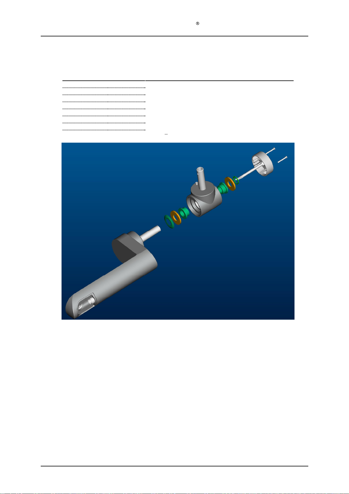
1.9.1
F
ixed lamp head
Required items
Part #
# of items
Description
128
-0-
610
1
Housing top module
128
-0-
400
1
Positioning arm module
128
-1-
914
2
Aluminium washer
s
128
-1-
912
1
Conic spring
128
-1-
916
1
Circlip
128
-1-
202
1
Power cable
From PS to lamp head
(fixed lamp head only)
128
-0-
810
1
Housing back module
128
-1-
928
4
Screw
s
PT 4x30
128
-0-
439
1
System electronics module
128
-1-
921
6
Screw
s
PT 2,5x8
128
-0-
750
1
Light module
128
-0-
820
1
Housing bottom module
128
-1-
929
4
Screw
s
PT 4x10
128
-1-
890
1
Main arm mini cover (moulded plastic)
128
-1-
923
2
Screw
s
PT 3x10
128
-1-
945
1
Ca
ble tension release
(fixed lamp head only)
Assembly description
Step 1)
Assemble position arm module (128
-0-
400) to housing top module (128
-0-
610) by sliding
the short axle of the main arm (128
-0-
428) thru the housing top slide bearing (128
-1-
632).
Step 2)
Slide an alumi
nium washer (128
-1-
914), a conical spring (128
-1-
912) and another
aluminium washer (128
-1-
914) onto the short axle of the main arm (128
-0-
428) from the
inside of the housing.
Step 3)
Compress the conical spring (128
-1-
912) and assemble the circlip (128
-1-
916). Thi
s
is
easiest
done with a special made tool
(s
ee pictures)
. Make sure that the circlip is located
securely in the groove.
This is very important.
Step 4)
Assemble power cable (128
-1-
302) by inserting the cable thru the positioning arm module
(128
-0-
400). Leave exc
ess cable inside the lamp head to simplify assembly in a later step.
Step 5)
Position housing back module (128
-0-
810) at the back end of the housing top module (128
-
0-
610). Do not assemble with screws yet.
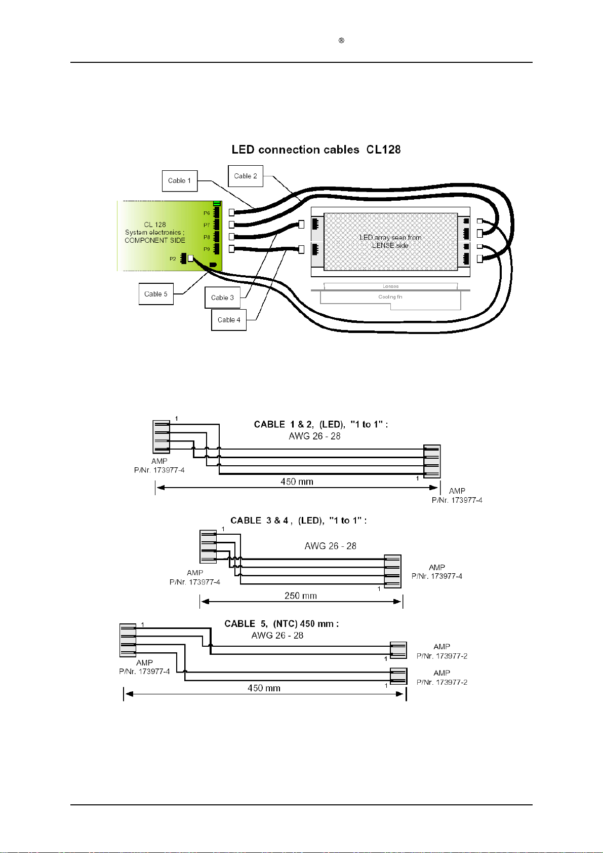
Step 6)
Insert power cable (128
-1-
302) ends into appropriate rece
ptors (cable marked 1 is plus [+],
cable marked 2 is minus [
-
]), fan cable plug from housing back module (128
-0-
810) and tail
from the user interface of the housing top module 128
-0-
610 into appropriate connectors on
the system electronics module (128
-0-
439
). Refer to cable spec from Kitron Development
06.03.2002: "LED cables CL128, Rev. A".
Step 7)
Fasten the system electronics module (128
-0-
439
) to the housing top module (128
-0-
610)
using the six PT 2,5x8 screws (128
-1-
921). And pull out the excess powe
r cable (128
-1-
302) from the lamp head.
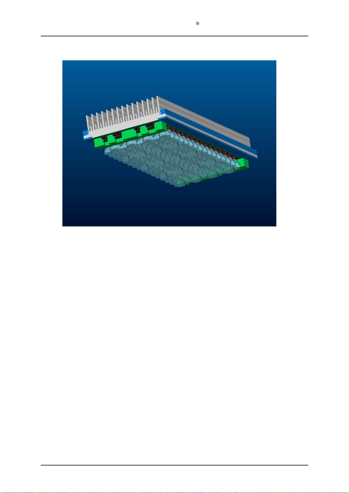
Step 8)
Plug the six cables from the system electronics module (128
-0-
439
) into the appropriate
connectors on the LED
-
panels (128
-1-
762) of the light module (128
-0-
750).
Step 9)
Tidy the cables from the system electronics modul
e (128
-0-
439) by inserting them thru the
four miniature cable holders (128
-1-
944) on the light module (128
-0-
750).
Step 10)
Seat the light module (128
-0-
750) properly in the housing top module (128
-0-
610).
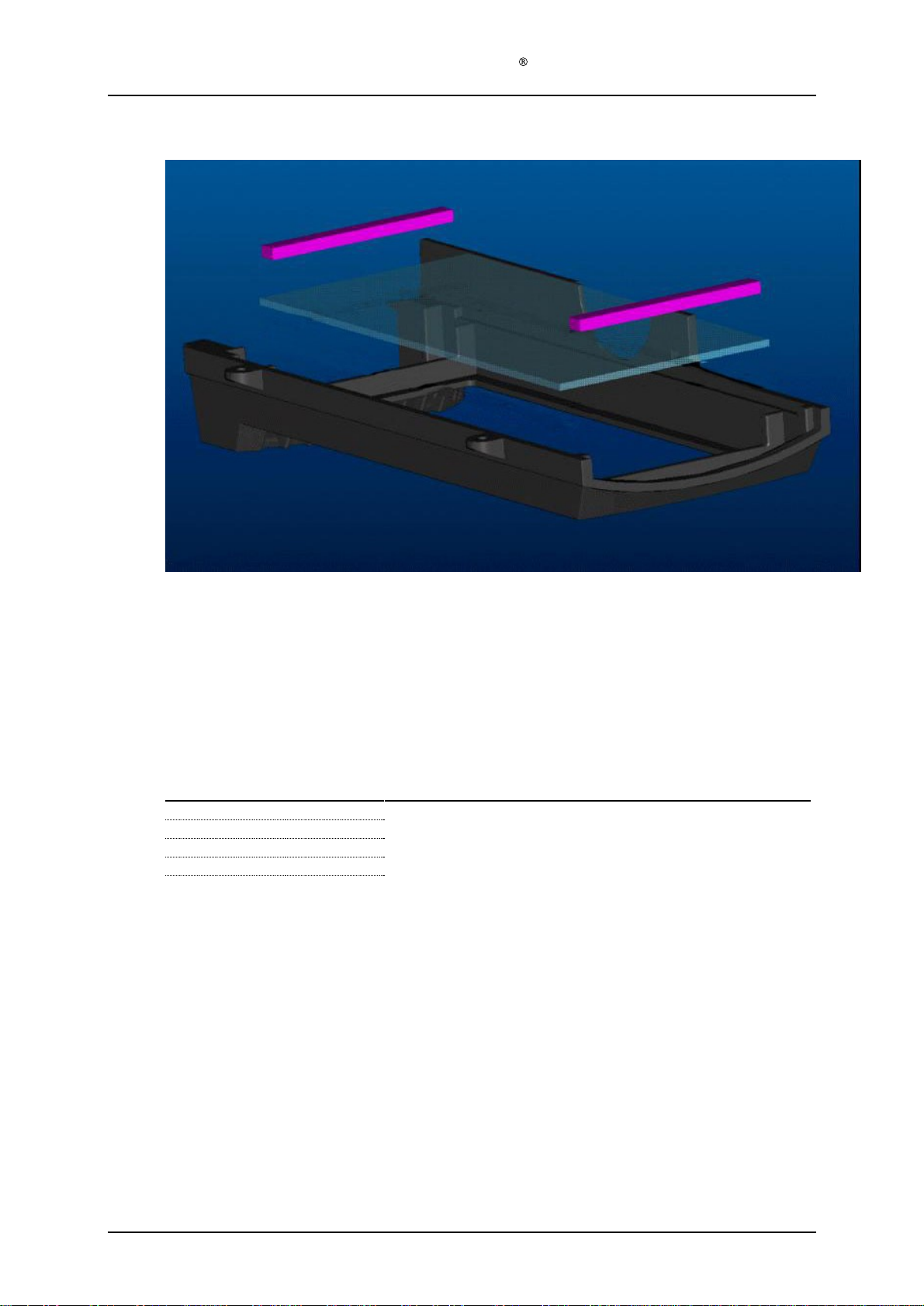
Step 11)
Remove the protective foil from the protective window
(128
-1-
826) of the housing bottom
module (128
-0-
820).
Step 12)
Assemble the housing bottom module (128
-0-
820) to the housing top module (128
-0-
610)
using the four PT 4x10 screws (128
-1-
929).
Step 13)
Fasten the housing back module (128
-0-
820) to the rest of the lamp head us
ing the four PT
4x30 screws (128
-1-
928).
Step 14)
Assemble the main arm mini cover (128
-1-
890) to the positioning arm module (128
-0-
400)
using the two PT 3x10 screws (128
-1-
923).
Step 15)
Assemble the cable tension release (128
-1-
945) around the power cable (128
-1-
302) and
inserting it into the T
-
piece cover (128
-1-
424) of the positioning arm module (128
-0-
400).