AL-KO 2LINK User manual


de
2 695766_a
Inhaltsverzeichnis
DE Original-Montageanleitung........................................................................................3
EN Translation of the original installation instructions................................................... 7
FR Traduction de la notice de montage originale........................................................11
© 2018
AL-KO Vehicle Technology, Germany
This documentation - or excerpts thereof - may only be copied or made accessible to third parties with
the express permission of the AL-KO VT. We reserve the right to make functional modifications to re-
flect technological advances.

de
695766_a 3
ORIGINAL-MONTAGEANLEITUNG
Inhaltsverzeichnis
Zu dieser Dokumentation.........................................................................................................................3
Sicherheitshinweise..................................................................................................................................3
Bestimmungsgemäße Verwendung......................................................................................................... 3
Montage TPMS-Empfänger und TPMS-Sensoren.................................................................................. 4
Zu dieser Dokumentation
Lesen Sie diese Dokumentation vor der Inbetriebnahme durch. Dies ist Voraussetzung für sicheres
Arbeiten und störungsfreie Handhabung.
Beachten Sie die Sicherheits- und Warnhinweise in dieser Dokumentation und auf dem Produkt.
Diese Dokumentation ist permanenter Bestandteil des beschriebenen Produkts und soll bei Veräu-
ßerung dem Käufer mit übergeben werden.
Zeichenerklärung
ACHTUNG!
Genaues Befolgen dieser Warnhinweise kann Personen- und / oder Sachschäden vermeiden.
.
Spezielle Hinweise zur besseren Verständlichkeit und Handhabung.
Sicherheitshinweise
GEFAHR!
Achtung - Lebensgefahr!
Arbeiten unter dem Fahrzeug ohne geeignete Abstütz- und Sicherheitsmaßnahmen sind le-
bensgefährlich! Verwenden Sie immer eine Hebebühne oder eine Montagegrube und sichern
Sie ihr Reisemobil gegen Eigenbewegungen.
Alle in dieser Montageanleitung beschriebenen Arbeiten dürfen nur von geschultem Fachpersonal
durchgeführt werden!
Bestimmungsgemäße Verwendung
Das AL-KO 2LINK Reifendruckkontrollsystem TPMS darf nur mit der AL-KO 2LINK-Box verwendet wer-
den. Der Anschluss an nicht freigegebene Komponenten kann zu Funktionsstörungen führen und irre-
parablen Schäden führen.
de
4 695766_a
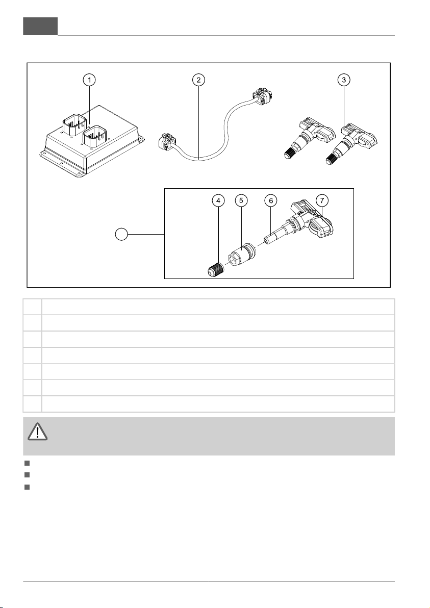
Montage TPMS-Empfänger und TPMS-Sensoren
3
1 TPMS-Empfänger
2 TPMS-Kabelbaum
3 TPMS-Sensor mit Ventil (2 Stück); weitere Sensoren (je 2 Stück) optional erhältlich
4 Ventilkappe
5 Schraubenmutter mit Dichtungsring
6 Ventil
7 TPMS-Sensor
ACHTUNG!
Schläuche und Kabel nicht über scharfkantige Ecken führen!
Kantenschutz verwenden!
Kabelbaum nicht über bewegliche oder heiße Teile führen.
Kabelbaum nicht durch Druck, Zug oder Scherung belasten.
Kabelbaum nie an der Bremsleitung befestigen.

de
695766_a 5
TPMS-Empfänger montieren
.
Vor der Montage des TPMS-Empfängers
muss die 2LINK-Box installiert sein, siehe
Montageanleitung 695469.
Je nach Anwendungsfall können Sie den TPMS-
Empfänger an das ATC oder eine Energieversor-
gung anschließen.
1. TPMS-Empfänger (1) zwischen der 2LINK-Box
und einer Energieversorgung (ATC, 12-Volt
Batterie) montieren. Beachten Sie die Kabel-
länge.
2. 2LINK-Kabelbaum aus der 2LINK-Box ziehen.
3. 2LINK-Kabelbaum in den TPMS-Empfänger
(1) stecken.
4. Ein Ende des TPMS-Kabelbaums (2) in den
TPMS-Empfänger (1) stecken, das andere
Ende in die 2LINK-Box stecken.
5. Kabelbäume fixieren.
.
Wenn kein ATC installiert ist, muss die Spannungsversorgung direkt über den 13-poligen Ste-
cker hergestellt werden:
Ader am 2LINK Kabelbaum Pin am 13-poligen Stecker
12 V (+) ATC_12V (rot) 9 (Dauerplus)
Masse (-) ATC_GND (schwarz) 13

de
6 695766_a
TPMS-Sensoren montieren
1. Druck vom Reifen ablassen.
2. Reifen von der Felge montieren.
3. Reifenventil oder alten TPMS-Sensor von der
Felge demontieren.
4. Ventilloch und den Rand der Felge von ätzen-
den Stoffen und Schmutz reinigen.
5. Ventilkappe (4) vom TPMS-Sensor (3) ab-
schrauben und Schraubenmutter (5) lösen.
6. TPMS-Sensor (3) von innen in die Felge ste-
cken.
7. Schraubenmutter (5) auf das Ventil setzen und
mit einem Drehmoment von 4 Nm festziehen.
8. Reifen auf Felge montieren. Darauf achten,
das der TPMS-Sensor (3) bei der Montage
nicht beschädigt wird.
9. Reifen befüllen.
10. Ventilkappe (4) auf das Ventil schrauben.
11. Rad auswuchten.
.
Die anderen TPMS-Sensoren auf die glei-
che Weise montieren.
en
695766_a 7
TRANSLATION OF THE ORIGINAL INSTALLATION INSTRUCTIONS
Contents
About this documentation........................................................................................................................ 7
Safety instructions....................................................................................................................................7
Designated use........................................................................................................................................ 7
Installation of the TPMS receiver and TPMS sensors............................................................................ 8
About this documentation
Please read this document before use. This is essential for safe working and trouble-free handling.
Comply with the safety and warning instructions in this documentation and on the product.
This document is a permanent component of the described product, and should remain with the
machine if it is sold to someone else.
Explanation of symbols
CAUTION!
Following these warning instructions can help to avoid personal injuries and/or damage to pro-
perty.
ADVICE
Special notes for ease of understanding and regarding handling.
Safety instructions
DANGER!
Important – Danger of fatal injury!
Working under the vehicle without suitable support and safety measures represents a risk of
fatal injury! Always use a lifting platform or an assembly pit, and secure your motorhome to
prevent inadvertent movements.
All of the work described in these installation instructions may only be carried out by trained technical
personnel!
Designated use
The AL-KO 2LINK tyre pressure monitoring system (TPMS) may only be used with the AL-KO 2LINK
box. Connection to non-approved components may result in malfunctions and irreparable damage.

en
8 695766_a
Installation of the TPMS receiver and TPMS sensors
3
1 TPMS receiver
2 TPMS wiring harness
3 TPMS sensor with valve (2 pieces); additional sensors (2 pieces each) optionally available
4 Valve cap
5 Screw nut with sealing ring
6 Valve
7 TPMS sensor
CAUTION!
Do not lay hoses and cables over sharp-edged corners!
Use edge protection!
Do not lay wiring harness over moving or hot parts.
Do not strain wiring harness due to pressure, pulling or shearing.
Never attach wiring harness to a brake line.

en
695766_a 9
Installing the TPMS receiver
ADVICE
Before installing the TPMS receiver, the
2LINK box must be installed, see installa-
tion instructions 695469.
Depending on the application, the TPMS receiver
can be connected to the ATC or an energy supply.
1. Install the TPMS receiver (1) between the
2LINK box and an energy supply (ATC, 12-volt
battery). Please note the cable length.
2. Pull the 2LINK wiring harness out of the 2LINK
box.
3. Plug the 2LINK wiring harness into the TPMS
receiver (1).
4. Plug one end of the TPMS wiring harness (2)
into the TPMS receiver (1) and plug the other
end into the 2LINK box.
5. Fix the wiring harness in place.
ADVICE
If no ATC is installed, the power supply must be connected directly via the 13-pin connector plug:
Wire on the 2LINK wiring har-
ness
Pin on 13-pin connector plug
12 V (+) ATC_12V (red) 9 (continuous pulse)
Earth (-) ATC_GND (black) 13
en
10 695766_a
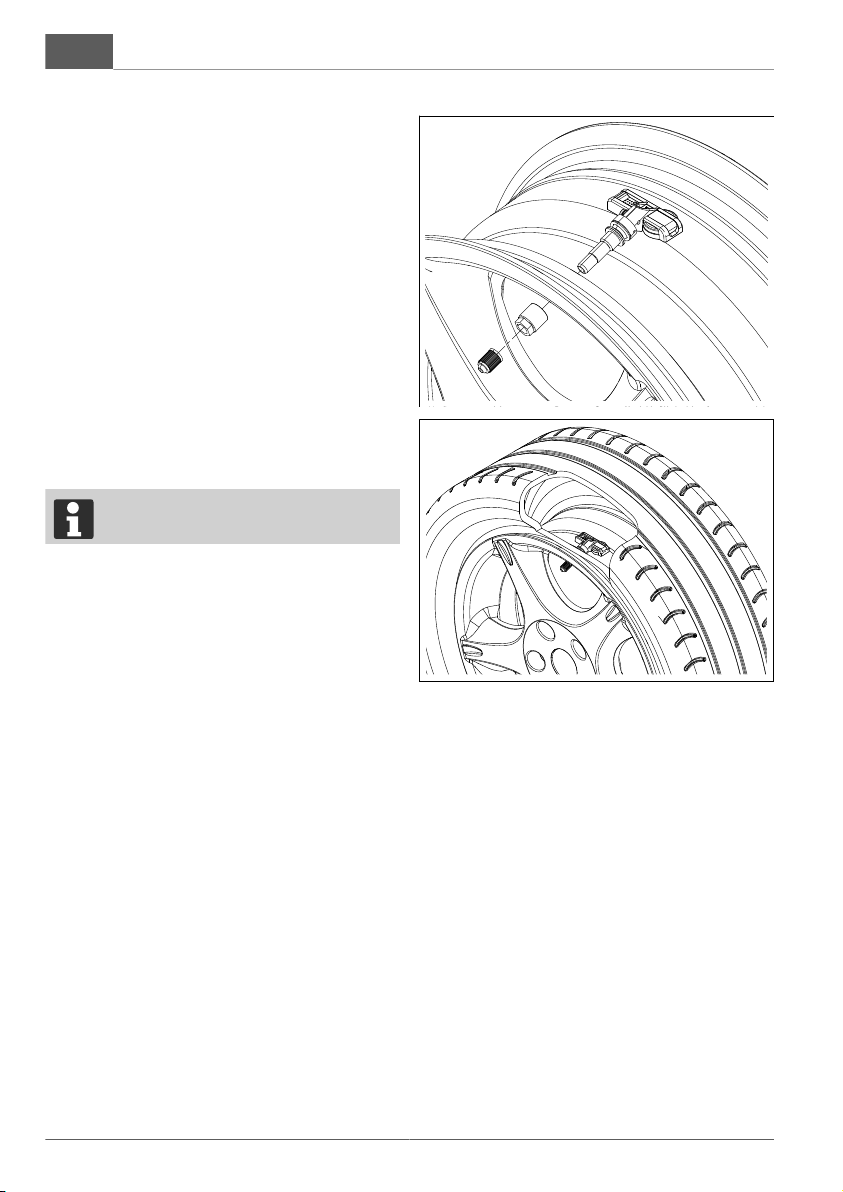
Installing the TPMS sensors
1. Release the pressure from the tyre.
2. Remove the tyre from the rim.
3. Remove the tyre valve or old TPMS sen-
sor from the rim.
4. Clean the valve hole and the edge of rim of any
corrosive substances and dirt.
5. Unscrew the valve cap (4) from the TPMS sen-
sor (3) and loosen the screw nut (5).
6. Insert the TPMS sensor (3) into the rim from
the inside.
7. Place the screw nut (5) on the valve and tighten
to a torque of 4 Nm.
8. Mount the tyre on the rim. Make sure that the
TPMS sensor (3) is not damaged during moun-
ting.
9. Inflate the tyre.
10. Screw the valve cap (4) onto the valve.
11. Balance the wheel.
ADVICE
Install the other TPMS sensors in the
same way.
Other manuals for 2LINK
2
Table of contents
Languages:
Other AL-KO Controllers manuals


Popular Controllers manuals by other brands

Digiplex
Digiplex DGP-848 Programming guide

YASKAWA
YASKAWA SGM series user manual

Sinope
Sinope Calypso RM3500ZB installation guide

Isimet
Isimet DLA Series Style 2 Installation, Operations, Start-up and Maintenance Instructions

LSIS
LSIS sv-ip5a user manual

Rockwell Automation
Rockwell Automation 1769-L31 installation instructions


