Alarko OPTIMA 5/8 User manual

OPTİMA
5/8, 4/10, 4/8, 4/4, 3/12-180,
3/10-180 3/7-180, 2/10-180
C�rculat�on Pump
Operat�ng Instruct�on

Code No: A.7.1.10� Rev�s�on Date: 26082022

��
1. CAUTION......................................................................................................................................... 1
2.WARNINGS ANDSYMBOLS.......................................................................................................... 1
2.1Typesof Symbols and Warn�ngs............................................................................................. 1
3. GENERAL........................................................................................................................................ 2
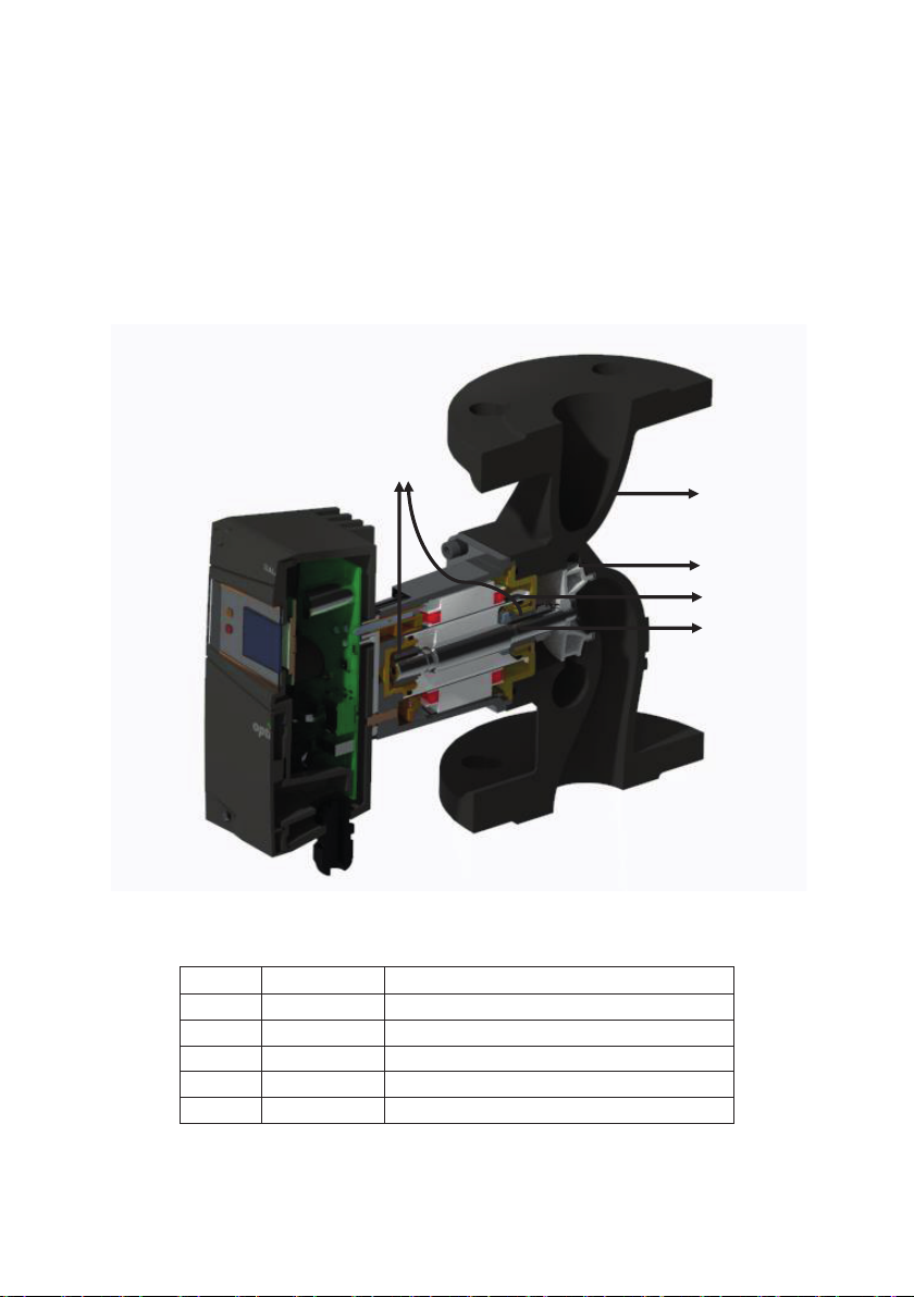
3.1Descr�pt�onof the Pump .......................................................................................................... 2
3.2Appl�cat�ons (Intended Use) .................................................................................................... 3
3.3Pumped L�qu�ds....................................................................................................................... 3
3.4Operat�ng Cond�t�ons............................................................................................................... 3
3.5Insulat�on Shells...................................................................................................................... 4
4. CONTENTS OF THE PACKAGE, LIFTING, TRANSPORTATITON AND STORAGE ................... 4
4.1Contents of the Package ......................................................................................................... 4
4.2L�ft�ng ....................................................................................................................................... 4
4.3Transportat�on and Storage ..................................................................................................... 5
5. PUMP DETAILS .............................................................................................................................. 5
5.1Nameplate ............................................................................................................................... 5
5.2Techn�cal Data......................................................................................................................... 6
6.PUMP INSTALLATION.................................................................................................................... 7
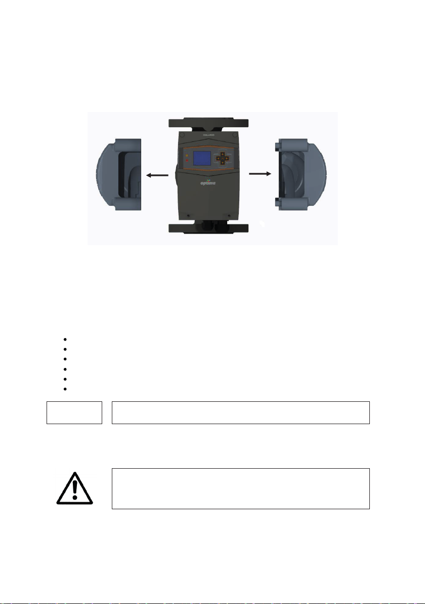
6.1Pos�t�on�ng ............................................................................................................................... 7
6.2Mechan�cal Installat�on ............................................................................................................ 9
6.3F�ll�ng and Vent�ng ................................................................................................................. 11
6.4Cable/Fuse Select�onand Electr�cal Installat�on................................................................... 11
6.5Parallel/Back-up Operat�on.................................................................................................... 14
7. DISPLAY AND SETTINGS............................................................................................................ 15
7.1Graph�cal D�splay .................................................................................................................. 15
7.22-D�g�t D�splay........................................................................................................................ 18
8.FIRST START-UP, CONTINUOUS OPERATION ANDSHUTDOWN.......................................... 20
9. OPERATING MODES ANDSELECTION CRITERIA ................................................................... 21
9.1Manual Operat�ng Mode ........................................................................................................ 22
9.2Constant Pressure Operat�ng Mode ...................................................................................... 22
9.3Var�able Pressure Operat�ng Mode ....................................................................................... 23
9.4Operat�ng Mode Select�onCr�ter�a ........................................................................................ 25
10.ADDITONAL ACCESSIORIES ...................................................................................................... 26
11.WARRANTY, MAINTENANCE AND SERVICE ............................................................................ 26
12.FAULTS, CAUSES AND REMEDIES ........................................................................................... 27
13.DISMALTLING............................................................................................................................... 32
14.DISPOSAL..................................................................................................................................... 33
15.APPANDIX..................................................................................................................................... 34
15.1D�mens�ons ............................................................................................................................ 34
15.2General Select�onChart and Performance Curves ............................................................... 35

1
1. CAUTION
Read th�s manual carefully. The �nformat�ong�venhere compr�sesessent�al �ssueswh�ch �s requ�red
for the pump operatorsor users.
CAUTION
If you need any �nformat�on later on, please refer to th�s manual
The manufacturer of the Opt�mapumps, Alarko-Carr�er, prov�descustomer serv�ce and reta�l�ng
operat�ons onthe f�eldsof heat�ng, cool�ng, vent�lat�on, water treatment and pressur�zat�onnat�onw�de
w�th �ts 68 years of exper�ence. Please contact your author�zed Alarko-Carr�er customer serv�ce �f you
need any �nformat�onor encounter aproblem.
The deta�ls �n the follow�ng pages apply to Opt�ma 5/8, 4/10, 4/8, 4/4, 3/12-180, 3/10-180 3/7-180, 2/10-180
types.
2. WARNINGS AND SYMBOLS
Th�s appl�ance can be used by ch�ldrenaged from 8years and above and persons w�th reduced
phys�cal, sensory or mental capab�l�t�esor lack of exper�ence and knowledge �f they have beeng�ven
superv�s�onor �nstruct�onconcern�ng use of the appl�ance �n asafe way and understand the hazards
�nvolved. Ch�ldren shall not play w�th the appl�ance. Clean�ng and user ma�ntenance shall not be made
by ch�ldren w�thout superv�s�on.
2.1Types of Symbols and Warn�ngs
If these warn�ngs are not taken �nto account, �t may result �n death or
�njury.
If these warn�ngs are not taken �nto account, ser�ous �njur�es or death
may occur due to electr�c shock.
CAUTION
If these warn�ngs are not taken �nto account, safeoperat�on or the
protect�on of the pump may fa�l.

2
3. GENERAL
3.1Descr�pt�on of the Pump
Alarko Opt�ma�s abrand new type of c�rculat�onpump wh�ch regulates�ts speed accord�ng to the
system needsby the ECM (Electron�c Commutated Motor) technology and the controller on�t, as well
as savesenergy w�th �ts var�oustypesof operat�ng mode cho�ces. The operat�ng modesare manual,
constant pressure and var�able pressure. See sect�on7.1.1, 7.2.2and 9. The pump operates
accord�ng to the operat�ng mode and head sett�ngswh�ch are setfrom the controller.
The ma�n components and the�r mater�als are g�ven�n the follow�ng f�gure and table.
F�gure 3.1: Cross-sect�on Draw�ng of the Pump
No Component Mater�al
1 Pump hous�ng Cast �ron(EN-GJL-200)
2Impeller Plast�c (mod�f�ed PPO - %30 GF)
3 Rotor can Compos�te
4 ShaftSta�nless steel (1.4021 or 1.4034)
5 Bear�ngsCarbon (metal �mpregnated)
Table 3.1: L�st of the Ma�n Components
5
1
2
3
4

3
3.2Appl�cat�ons (Intended Use)
Alarko Opt�mapumpsare developed for the c�rculat�onand pressur�zat�onof the water flow�ng �n the
heat�ng and a�r cond�t�on�ng systemslocated �n the res�dent�al, commerc�al and �ndustr�al
establ�shments.
CAUTION
Opt�ma pumps can be used only for thepurposes that are stated �n th�s
manual. Themanufacturer and thedealer are not respons�ble forthe
results of them�suse.
3.3Pumped L�qu�ds
Asthe l�qu�d, only water should be used. It should be free from sol�d part�clesand �s notm�xed w�th
any add�t�ves, e.g. ant�-freeze. To avo�d any k�nd of scal�ng or corros�on, the water w�th�n the system
should meet the cr�ter�a below:
Total Heat�ng
Output [kW]
Sum of
Alkal�ne
Earths
[mole/m
3
]
Total
hardness
[0d]
pH value
at 25°C
Oxygen
[mg/l�ter]
Electr�cal
Conduct�v�ty at
25°C [μS/cm]
... ≤50 ≤3.0 ≤16.8
8.2 – 10.0 < 0.02 < 100
50 < ... ≤200 ≤ 2.0 ≤11.2
200 < ... ≤ 600 ≤1.5 ≤ 8.4
600 < ... ≤0.02 ≤0.11
Table 3.2: Propert�esof the water used �n heat�ng systems1
1Source: VDI 2035 – Part 1 and 2
3.4Operat�ng Cond�t�ons
Alarko Opt�mapumpsare developed for the c�rculat�onand pressur�zat�onof the water flow�ng �n the
heat�ng and a�r cond�t�on�ng systemslocated �n the res�dent�al, commerc�al and �ndustr�al
establ�shments.
Input Voltage: S�ngle Phase 230 Volts AC (± 10%) and 50 Hz (earth protected).
Water Temperature: Up to +110°C
System Pressure: For m�n�mum and max�mum water pressure see Table 4.2 and Table 4.3
Amb�ent Temperature: -10°C to +40°C
Thecond�t�ons (voltage, pressure, temperature) of thepump wh�le
operat�ng should be between the l�m�ts g�ven above.

4
3.5Insulat�on Shells
The �nsulat�onshell �s des�gned to m�t�gate the thermal losses�n heat�ng systemsand del�vered w�th
the pump. It �s made of polypropylene foam and thoroughly mounted onthe pump by �ts perfectly
f�tt�ng des�gn.
Remove the �nsulat�on shells from the hous�ng before the pump �nstallat�on. See F�gure 3.2.
F�gure 3.2: Insulat�onShells
4. CONTENTS OF THE PACKAGE, LIFTING, TRANSPORTATITON
AND STORAGE
4.1Contents of thePackage
The package conta�ns the follow�ng;
Pump
Insulat�on shells
Manual
Cert�f�cate of Warranty
2 p�ecesof gasket (for 5/8, 4/10, 4/8, 4/4 pump types)
1 p�ecesof O-r�ng (used betweenpump hous�ng-motor hous�ng)
CAUTION
Do not throw away the �nsulat�on shells.
4.2L�ft�ng
The pump should be l�fted from the pump hous�ng.
Do not l�ft the pump from the controller box.

5
L�ftthe pump by observ�ng the local l�ft�ng and handl�ng regulat�ons.
4.3Transportat�on and Storage
Amb�ent Temperature dur�ng the Transportat�on and Storage: -25°C to +40°C
The pump should be protected from mo�sture, �mpacts and frost dur�ng the transport and storage.
CAUTION
Improper transportat�on or storage may lead to damage to the product.
It �s adv�sed to check and exam�ne the product whether �t �s the ordered type and del�vered
undamaged.
If the pump �s damaged or deformed, �t should not be used w�thoutan approval of the Alarko-Carr�er
customer serv�ces.
5. PUMP DETAILS
5.1Nameplate
The �nformat�on g�ven�n the nameplate �s shownbelow:
F�gure 5.1: Sample of aNameplate

6
Number Descr�pt�on
1 F�rst d�g�t of the nom�nal flange d�ameter
2Max. head
3 Pump hous�ng length
4 Product�onyear
5 M�n. and Max. power
6Temperature class
7 Enclosure class
8Inputfrequency
9 Inputvoltage
10 Ser�al number
11 Max. system pressure
12Acqu�red standards
13 Max. current
14 Energy Eff�c�ency Index (EEI)
15 Operat�ng Instruct�on L�nk
16Factory Manufactur�ng Code
Table 5.1: Descr�pt�onof the Nameplate Data
5.2Techn�cal Data
5/8
4/10
4/8
4/4
3/12-180
3/10-180
3/7-180
2/10-180
Max. Head [m]
According to pump type, see Appandix
Max. Flow [m3/h]
According to pump type, see Appandix
Speed [rpm]
1800 –
4600
1800 –
4600
1800 –
4600
1600 –
3600
1800 –
4900
1800 –
4600
1600 –
3800
1800 –
4600
Input Voltage and Frequency 1~ 230 V AC ± %10, 50 Hz, PE
Nominal Current [A]
1.35 1.4 1.35 1 1.34 1.4 1 1.4
Power Consumpn [W]
15 – 300 12 – 190 15 – 300 12 – 125 16 – 300 12 – 190 12 – 125 12 – 190
Energy Eciency Index (EEI)
≤0.23
Insuln Class F
Enclosure Class
IP X4D
Temperature Class
TF 110
Max. System Pressure
PN 6/10(1) PN10
Emied sound pressure < 56 dB
Relve Humidity
< %90
Pump Dimensions
see Appandix
(1) Pump is suitable for both pressure values.
Table 5.2Techn�cal Data

7
In order to avo�d the no�se and damage due to the cav�tat�on, the m�n�mum �nletpressure valuesare
g�venonthe table below.
Nominal
Diameter
Water Temperature
G1 1/2"
0,4 bar
0,7 bar
1,0 bar
1,5 bar
G2
0,4 bar
0,7 bar
1,0 bar
1,5 bar
DN40
0,5 bar
0,8 bar
1,3 bar
2,0 bar
DN50
0,5 bar
0,8 bar
1,3 bar
2,0 bar
Table 5.3: M�n�mum InletWater Pressure Values
CAUTION
Thevalues l�sted �n thetable apply to pumps �nstalled up to 300 meters
abovesea level. Forh�gher alt�tudes add +0.01 bar/100m to therequ�red
relat�ve �nlet pressure.
6. PUMP INSTALLATION
Mechan�cal and electr�cal �nstallat�on must be carr�ed out by qual�f�ed
personnel and �n accordance w�th the�nstruct�ons on th�s manual and
also w�th appl�cable regulat�ons.
CAUTION
Before any �nstallat�on, thep�pework should be checked for
contam�nat�on and flushed �f there �s any.
6.1Pos�t�on�ng
Thepump should be �nstalled �nto thep�pework w�thout any stra�n or
bear�ng the we�ght of the p�pework.
The f�guresg�venbelow are to be taken�nto cons�derat�on dur�ng the �nstallat�on.
The pump must be connected to the p�pework w�thoutany stra�n, do notbear the we�ghtof the
p�pework and the motor shaftmust be parallel to the ground.

8
F�gure 6.1: Correct Pump Pos�t�ons Wh�le Vert�cally and Hor�zontally Installed to the P�pework
The pump must be not perpend�cular to the ground.
F�gure 6.2: Incorrect Pump Pos�t�ons
The pos�t�onof the control box can be changed �n order to see and use the d�splay eas�er. To adjust
the pos�t�on, the 4 bolts, wh�ch hook the motor hous�ng and pump hous�ng together, are removed and
the motor hous�ng �s adjusted by rotat�ng �t to the appropr�ate one from theallowed pos�t�ons and
reconnected to the pump hous�ng w�th bolts.
Donot separate themotorhous�ng from pump hous�ng. Rotat�on
operat�on should be done carefully and slowly. Seal damage causes
leakage.

9
F�gure 6.3: Control Box Pos�t�onAdjustment
6.2Mechan�cal Installat�on
1. Make sure that all the p�p�ng of the system must be done before beg�nn�ng the �nstallat�on.
2. Close the valvesonthe �nlet and outlets�de to �solate the pump from water flow.
3. Check the coherence of the system pressure and the m�n. & max. pressure values of the pump.
See Sect�on 5.2.
4. Mount the pump to the p�peswh�le tak�ng the arrow onthe pump hous�ng �nto
cons�derat�on. The water flow of the system and the arrow onthe hous�ng must be �n the
same d�rect�on.
5. For threaded p�pe connect�on; place the flat gaskets onto the s�desof the pump. Make
sure that the gaskets do not prevent any water flow.
6. Us�ng astrap wrench or spanner, hold the pump from the pump hous�ng and screw the
nuts. See F�gure 6.4
F�gure 6.4: Threaded P�pe Connect�on
7. For flanged p�pe connect�on; place the suppl�ed flat gaskets onto both s�desof the pump.
Make sure that the gaskets do not prevent any water flow.
8. Use the washers, bolts and nuts g�ven �n the Table 6.1 to f�x the pump to the p�pes.

10
9. Check the F�gure 6.5 for washer, bolt and nut order. See Table 6.1 for the recommended
t�ghten�ng torques for the bolts used �n the pump f�x�ng.
F�gure 6.5 Flanged P�pe Connect�on
Pressure Bolt and Nut Type Recommended Tightening Torque Value
PN 6 M12 40 Nm - 60 Nm
PN 10
M16
70 Nm - 90 Nm
Table 6.1 Recommended T�ghten�ng Torque Values
10. After complet�ng the connect�on, openthe �solat�ng valvesof �nlet and outlet s�desand
check �f there �s any leak�ng.
11. Make sure that the four condensate dra�n grooves around the pump are open. See F�gure 6.6.
.
1 Washer
2 Nut
3 Bolt

11
F�gure 6.6: Condensate Dra�n Grooves
12. After the �nstallat�on �s completed, place the �nsulat�on shells as shown �n F�gure 6.7.
.
F�gure 6.7: Plac�ng the Insulat�on Shells
6.3F�ll�ng and Vent�ng
In order to ensure the pump to operate eff�c�ently also w�thout any damage and no�se, the a�r �n the
system must be vented and the system pressure must be betweenthe valuesg�ven�n Table 5.2and
Table 5.3. To fully vent the a�r from the system, the pump can be runfor a wh�le.
A�r vent�ng should not be doneby loosen�ng any bolts of motoror pump
hous�ng.
Condensate
Dra�n Grooves

12
6.4Cable/Fuse Select�on and Electr�cal Installat�on
Electr�cal �nstallat�on must be carr�ed out by qual�f�ed personnel and �n
accordance w�th the�nstruct�ons on th�s manual and also w�th appl�cable
regulat�ons.
Before work�ng on thepump, all poles of thepower supply must be
d�sconnected.
Thema�ns connect�on must havean earth�ng system. If not, thepump
should not be run.
For cable and fuse select�on, Table 6.2 should be cons�dered.
5/8 4/10 4/8 4/4 3/12-180 3/10-180 3/7-180 2/10-180
Cable
3 x 1.5 mm
2
Fuse
2A
Table 6.2: Cable and Fuse Values
Electr�cal connect�ond�agram �s g�venat F�gure 6.8.
F�gure 6.8: Electr�cal Connect�on D�agram
1. Check the phase and neutral outlets of the ma�ns.
2. Attach cable ferrules to the cable t�psappropr�ate to the cable d�ameter.
3. Take out the cover of the cable gland.
4. Remove the screws of the bottom cover. See F�gure 6.9.

13
F�gure 6.9: Removal of the Bottom Cover
5. Pull the power supply cable through the no.1 cable gland shown �n F�gure 6.10.
F�gure 6.10: Cable Gland V�ew
6. Connect the power supply cables to the socket named as “A” �n F�gure 6.10 appropr�ately,
as shown �n F�gure 6.8.
7. T�ghten the cable gland and make sure that the connect�ons�de of the cable �s loose enough.
8. Ref�t the cover. See F�gure 6.11. .
1
2
A
B

14
F�gure 6.11: Ref�tt�ng the Bottom Cover
The power cable should not be �n contact w�th the pump or p�pel�ne.
The voltage value of the ma�ns must be �n between the l�m�ts g�ven
�n Table 5.2
It �s recommended to use ares�dual-current dev�ce (RCD) to protect the user and the pump. The RCD
should be chosenaccord�ng to the nom�nal voltage and current of the pump and �t should be able to
tr�p on h�gh frequency leakages(type B) (The tr�pp�ng current should be lower than 3.5mA accord�ng to
the EN 60335).
6.5Parallel/Back-up Operat�on
Whereas the CCM module �s notoperat�ng or �nact�ve, when�nstall�ng more than one pump for back-
up or parallel operat�on, acheck valve must be connected for each pump.

15
7. DISPLAY AND SETTINGS
The control d�splay showsthe �nformat�onabout the pump statusand allowsthe user to set the
des�red mode to operat�on. Opt�ma pumpshave 3 d�fferent d�splay opt�ons wh�ch are graph�cal d�splay,
2-D�g�t and non-d�splay.
7.1Graph�cal D�splay
The graph�cal d�splay has 2 LEDs, f�ve control buttons and one TFT screen. See F�gure 7.1.
F�gure 7.1 : Control D�splay Layoutof Graph�cal D�splay
The layout of the buttons and d�splay:
1. Remote Control LED(YELLOW): It bl�nkswhengett�ng as�gnal from the bu�ld�ng automat�on
system.
2. FaultLED (RED): It �s onwhenthere �s a fault. Itbl�nkswhen there �s a warn�ng.
3. TFT D�splay: Shows the operat�ng modes and warn�ng/error messages.
4. “Left” Button
5. “Up”Button
6. “R�ght” Button
7. “Down” Button
8. “OK”Button: To nav�gate through the menu.
The ma�n menu �s shownbelow:
Nu. 1 showsthe “Start/Stop” �conwh�ch use for start/stop
and pause the pump.
Nu. 2showsthe “Operat�ng Mode Adjustment” �conthat
open the operat�ng modesuser �nterface.
Nu. 3 showsthe “Fault” �con. It �s appear�ng when
warn�ng/error occurred that g�vesthe �nformat�onabout fault
codes.
Nu. 4 showsthe “Remote Control”�conthat appears on
the screendur�ng the pump �s �ntegrated w�th the bu�ld�ng operat�ng system.
Nu. 5 shows the pump operat�ng modes�n graph�cal v�ew.

16
Nu. 6shows the current speed of the pump.
In the ma�n menu; �t �s sw�tch�ng betweenoperat�ng modesand pause the pump w�th the “OK”button
and d�rect�onkeys.
A wh�te frame appears onthe act�ve �con�n order to eas�ly sw�tch�ng betweenthe
menus and submenus.
7.2.1 Start / Stop
Whenthe pump �s �n operat�on, the pump �s stopped by press�ng the "OK" button
once on the ma�n screen on the "Start/Stop" �con.
The stopped pump �s restarted by press�ng the "OK" button.
7.2.2 Operat�ng Modes
To adjust the operat�ng modes, arr�ve uponthe “Operat�ng Mode Adjustment” �con
by us�ng the “Up” and “Down” buttons.
The “Operat�ng Mode Setup”�con�s the �conshown by the l�ne graph below the
“Start/Stop”�con.
Wh�le uponthe “Operat�ng Mode Adjustment” �con“ press “OK”buttonto select the
graph�cal v�ew area.
Press “OK”buttonto act�ve the operat�ng mode adjustment. Whenthe act�vat�on�s
on, the wh�te frame bl�nksaround the graph�cal v�ew.
In th�s menu; �t �s sw�tch�ng betweenoperat�ng modesw�th the “Left” and “R�ght” buttons.
Press “OK”button after select�ng the operat�ng mode.
Manuel Operat�ng Mode
Showsthe selected speed of the pump.
Manuel Operat�ng Mode �s chosenfrom operat�ng modesand press the “OK”buttonafter
select�on.
Press “Down” buttonto adjust des�red manual operat�ng po�nt and thenpress “OK”buttonto
select po�nt.
When the act�vat�on�s on, the wh�te frame bl�nks around the manual operat�ng po�nts.
The des�red speed �s mod�f�ed by “Up”-“Down” or “Left”-“R�ght” buttons w�th 50 rpm �ntervals.
Press “OK”button after select�on.
X
X
X
X

17
Constant Pressure Operat�ng Mode
Showsthe selected head w�th 0.5 meter �ntervals.
Constant Pressure Operat�ng Mode �s chosenfrom operat�ng modesand press the “OK”
button after select�on.
Press “Down” buttonto adjust des�red constant pressure operat�ng po�nt and thenpress “OK”
button to select po�nt.
Whenthe act�vat�on�s on, the wh�te frame bl�nksaround the constant pressure operat�ng
po�nts.
The des�red head �s mod�f�ed by “Up”-“Down” or “Left”-“R�ght” buttons w�th 0.5m �ntervals.
After 10m head, the �nterval scale r�ses to 1m.
Press “OK”button after select�on.
Var�able Pressure Operat�ng Mode
Shows the selected head w�th 0.5 meter �ntervals.
Var�able Pressure Operat�ng Mode �s chosenfrom operat�ng modesand press the “OK”button
after select�on.
Press “Down” button to adjust des�red var�able pressure operat�ng po�nt and thenpress “OK”
button to select po�nt.
Whenthe act�vat�on�s on, the wh�te frame bl�nksaround the var�able pressure operat�ng
po�nts.
The des�red head �s mod�f�ed by “Up”-“Down” or “Left”-“R�ght” buttons w�th 0.5m �ntervals.
After 10m head, the �nterval scale r�ses to 1m.
Press “OK”button after select�on
7.2.3 Fault Messages
In th�s submenu, the errorsand warn�ngswh�ch occur �n the pump are shown. Refer to the Sect�on12
for fault handl�ng.
“Fault” �con �s appear�ng whenwarn�ng/error occurred.
Errors/Warn�ngscodes appear onthe screen.
Press “OK”button uponon“Fault” �conand use d�rect�onkeysto see other faults
�f more than one faults.
“P”letter �nd�cates that awarn�ng was occurred.
“FaultLED” �s onwhen there �s error.
“E”and “F” letters�nd�cate that an error was occurred.
“FaultLED” bl�nkswhen there �s warn�ng. See the F�gure 7.1 Number 2.
X
X
X
X
p
X
E/F
X
This manual suits for next models
7
Table of contents
Other Alarko Water Pump manuals
Popular Water Pump manuals by other brands

CAT Pumps
CAT Pumps 1810 Series Service manual

Pentair
Pentair Berkeley LTHH Series Installation and operation manual

Crane
Crane Barnes SGV Series installation manual

Secoh
Secoh SLL-20 Service maintenance manual

SPX
SPX Johnson Pump Ultima Bilge 600GPH instruction manual

ARO
ARO 666100-344-C Operator's manual