OPERATING DESCRIPTIONS
OF CONTROLS AND CONNECTORS
HORIZONTAL DISPLAY
The seven position switch determines the time bose
used ond the type of display presented In tho three
TIME BASE A positions, the A sweep is connected to the
horizontal amplifier input. In the two TIME BASE B
positions, the B sweep is connected to the horizontal
amplifier input. In the two EXT. positions, an externally
derived sweep (coupled through the HORIZ INP T con
nector) is connected to the horizontal amplifier input.
In the B position, TIME BASE B is the only sweep. In
the B' INTENSIFIED BY ‘A* position. TIME BASE A is
used to brighten a portion of TIME BASE B. In the 'A'
DEL D BY B' position, the brightened portion, as seen in
the B' INTENSIFIED BY -A' position, will be expanded
the full width of the screen. In the 'A' position, TIME
BASE A is the only sweep. In the A’ SINGLE SWEEP
position, the RESET button controls start of the single
sweep (SEE RESET).
In all positions of the HORIZONTAL DISPLAY switch,
except A' and A- SINGLE SWEEP, the delayed trigger
is controlled by TIME BASE B. In all positions of the
HORIZONTAL DISPLAY switch, the time base used is
indicated by a light above the DELAY-TIME M LTIPLIER
control.
•/««*■ i 30
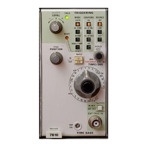
TRIGGERING MODE (2 switches)
For TIME BASE A, the five position red TRIGGERING
MODE switch selects one of four modes of triggering
(A TO., AC, DC. OR AC. IF RFJECT), plus synchronized
operation (HF SYNC). For TIME BASE B, the three posi
tion switch selects one of three modes of triggering
(A TO.. AC, or DC).
TRIGGER SLOPE (2 switches)
Tho TRIGGER SLOPE switch selocts the swoop trig
gering signal—the signal being displayed (+INT. or
INT.j, an externally derived triggering signal (-fEXT.
or —EXT.), or the power-line wave ( + LINE or—LINE).
In the -f- INT.f -fEXT., or -f-LINE positions, triggering oc
curs during the voltage rise of the triggering waveform.
In the —INT.r —EXT., or —LINE positions, triggering oc
curs during the voltage fall of tho triggering waveform.
STABILITY (2 controls)
The red STABILITY control adjusts the sweep for trig
gered or for free-running operation. When the TRIGGER
ING MODE switch is in the DC or AC positions (also AC,
LF REJECT, in TIME BASE A), the STABILITY control can
generally be used in the PRESET position. When the TRIG
GERING MODE switch is in the A TO, position, the STA
BILITY control is disabled. When the TRIGGERING
MODE switch is in the HF SYNC position (Time Base A),
the STABILITY control serves os the synchronizing control.
For manual operation of the variable STABILITY control,
see page 30.
31