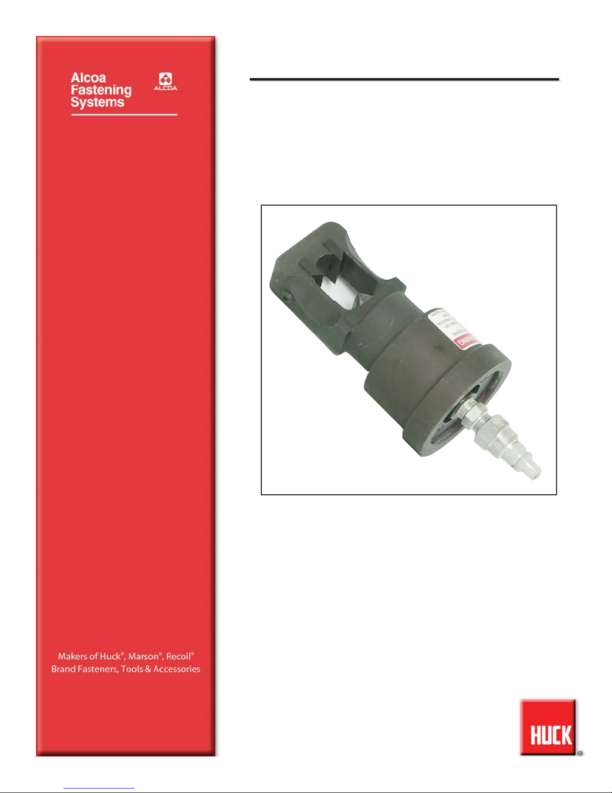
516, 520, 524, 528, 532, 536, M524 Hydraulic Collar Cutters Alcoa Fastening Systems
9
M
MAINTENANCE
AINTENANCE
Good Service Practices
The efficiency and life of any installation or removal tool
depends upon proper maintenance and good service
practices. Tools should be serviced by personnel who
are thoroughly familiar with them and how they operate.
A clean well lighted area should be available for servic-
ing the tool. Special care must be taken to prevent con-
tamination of hydraulic systems.
All parts must be handled carefully and examined for
damage or wear. Perishable parts such as o-rings and
seals should be kept on hand for replacement whenever
tool is disassembled.
See S
SPECIFICATIONS
PECIFICATIONS for fluid type. Dispose of fluid in
accordance with local environmental regulations.
Recycle steel, aluminum, and plastic parts in accordance
with local lawful and safe practices.
Components should be disassembled and assembled in
a straight line without bending, cocking or undue force.
Disassembly and assembly procedures outlined in this
manual should be followed. Appropriate hand tools and
soft materials to protect tools must be available. Only
standard hand tools are required. A half inch brass drift,
wood block and a vise with soft jaws will prevent damag-
ing tool.
Preventive Maintenance
Refer to the applicable section for A
ASSEMBLY
SSEMBLY and
D
DISASSEMBLY
ISASSEMBLY. For supplementary information refer to
T
TROUBLESHOOTING
ROUBLESHOOTING and illustrations.
With proper care, the cutter will remove 100 collars
before it may be necessary to replace the blades. The
estimated life of the Collar Cutter is 10,000 cycles or 5
years, depending on service conditions.
System Inspection
Operating efficiency of the cutter is directly related to the
performance of the complete system, including the cut-
ter, hydraulic hoses, trigger assembly and the POW-
ERIG® Hydraulic Unit. Therefore, an effective preventive
maintenance program includes scheduled inspections of
the system to detect and correct minor defects.
1. Inspect cutter for external damage.
2. Verify that hoses, fittings and trigger connections
are secure.
3. Inspect hydraulic hoses for signs of damage.
Replace if required.
4. Inspect cutter, hoses and POWERIG® during oper-
ation to detect abnormal heating, leaks or vibration.
POWERIG® Hydraulic Unit Maintenance
Hydraulic fluid should have a maximum contamination
level of ISO CODE 18/15 or SAE LEVEL 6. Portable fil-
tration on smaller powerigs and maintaining filters on
larger powerigs is recommended. Maintenance and
repair instructions are in applicable POWERIG Hydraulic
Unit instruction manuals.
Cutter Maintenance
At regular intervals, depending upon use, replace all
seals in the cutter. Spare seals and parts should be kept
on hand. Inspect cylinder bore and piston for scored sur-
faces, excessive wear or damage, and replace as neces-
sary.
Notes and Specifications for Standard Parts
All part numbers shown are available from Huck. The
500000 series numbers are standard parts which can
generally be purchased locally.
Needle Valve Adjustment
A needle valve has been designed into the hydraulic
cylinder of some of the cutters. The adjustment provides
for the proper piston RETURN stroke when using various
hydraulic units and hose combinations. Tool is shipped
with the valve set in the closed position.
Needle Valve Adjustment for the 940 POWERIG®
Hydraulic Unit: Turn needle valve clockwise to the closed
position.
Needle Valve Adjustment for the 918 POWERIG®
Hydraulic Unit:
1. Close needle valve clockwise. Depress trigger until
piston stops forward.
2. Open needle valve by turning slightly counterclock-
wise. Jog or activate switch. If valve is correctly
adjusted, piston will return to rear and pump shuts
off. Repeat procedure until cutter cycles normally.
3. If normal cutter operation cannot be attained, close
needle valve completely and start over at 1. Repeat
until requirements are met.
Needle Valve Adjustment Trouble-shooting:
Note: A normal piston cycle is when the piston goes fully
forward and fully back with one actuation of the switch.
Q. Piston partially returns and pump shuts off.
A. Needle valve not open enough.
Q. Piston partially or fully returns and pump will not shut
off.
A. Needle valve is open too far.
* Slic-Tite is a registered trademark of LA-CO Industries, Inc.
* TEFLON is a registered trademark of DuPont Corp.
CAUTIONS:
●Consult MSDS before servicing tool.
●Keep dirt and other material out of hydraulic
system.
●Separated parts most be kept away from dirty
work surfaces.
●Dirt/debris in hydraulic fluid causes failure in
POWERIG® Hydraulic Unit’s valves.
CAUTION: Do not use TEFLON®* tape on pipe
threads. Pipe threads may cause tape to shred
resulting in tool malfunction. (Slic-Tite is avail-
able in stick form as Huck P/N 503237.)
CAUTION: Always replace seals, wipers, and
back-up rings when tool is disassembled for any
reason.