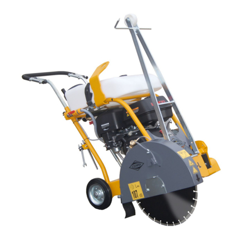
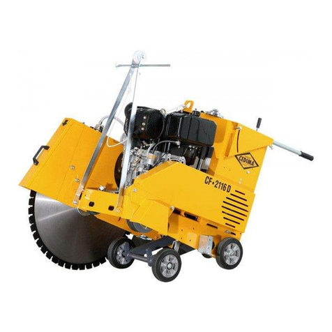
Cedima CF-12.4 E-TR Operator's manual

OPERATING MANUAL
and
SAFETY INSTRUCTIONS
JOINT CUTTER
CF-12.4 E-TR

ENGLISH
• CEDIMA® • Technical Documentation • All rights reserved as per DIN 34 • Subject to modifications due to progressive development •

CEDIMA®
Joint Cutter CF-12.4 E-TR
Article-No. 31 4110 5225
Revision index 002 Issue 21. 02. 2007
Serial number of the operating manual 70 9998 1001
Thank you for choosing a CEDIMA® product.
The more familiar you are with it, the easier you will find the use of a CEDIMA® product.
Therefore we kindly ask you:
to read the information gathered in this operating manual before you begin working with your
newly purchased product. You will find important notes concerning the operation so that you can
make the most out of the technical advantages offered by your CEDIMA® product. Moreover,
you will find useful tips for maintenance and for maintaining the safety of operation, accident
protection and value of your machine as much as possible.
CEDIMA® Diamantwerkzeug- und Maschinenbauges. mbH
ENGLISH
• CEDIMA® • Technical Documentation • All rights reserved as per DIN 34 • Subject to modifications due to progressive development •

CEDIMA®
Diamantwerkzeug- und Maschinenbauges. mbH
Celle/Germany
© Copyright CEDIMA® – Technical Documentation
All rights reserved as per DIN 34. No part of this document may be reproduced, adapted, stored
in a retrieval system or transmitted, in any from or bay any means, electronic, mechanical,
photocopying, recording or otherwise, or translated into a foreign language without the prior
consent of CEDIMA® in writing.
Warranty
The information contained in this publication may change without prior notice.
CEDIMA® do not give any guarantee for this publication. Furthermore,
CEDIMA® do not take any liability for faults which may be contained in this publication/spare
parts list nor for any secondary damages which may arise from the delivery, performance or use
of the material.
Trademark
is a registered trademark of CEDIMA®
Diamantwerkzeug- und Maschinenbauges. mbH
ENGLISH
• CEDIMA® • Technical Documentation • All rights reserved as per DIN 34 • Subject to modifications due to progressive development •

ENGLISHDEUTSCHFRANÇAIS
• CEDIMA® • Technical Documentation • All rights reserved as per DIN 34 • Subject to modifications due to progressive development •
Uniform Statement of Conformity
This ist to certify, that on the basis of the directive 98/37/CE (their modifications inclusive) of
the European Parliment and Community of 22. June 1998
the Joint Cutter CF-12.4 E-TR starting from year of manufacture 2005
of CEDIMA® Diamantwerkzeug- und Maschinenbauges. mbH,
Lärchenweg 3, D-29227 Celle/Germany
complies with the following standards DIN EN 12100-1, DIN EN 12100-2,
DIN EN 13862, EN 60204-1, 73/23/EEC,
89/336/EEC, 2000/14/EC, 2002/96/EC
Einheitliche Konformitätsaussage
Hiermit wird bestätigt, dass auf der Grundlage der Richtlinie 98/37/EG (inklusive deren
Änderungen) des Europäischen Parlaments und des Rates vom 22. Juni 1998
der Fugenschneider CF-12.3 E-TR ab Baujahr 2005
der CEDIMA® Diamantwerkzeug- und Maschinenbauges. mbH,
Lärchenweg 3, D-29227 Celle
mit folgenden Normen und Richtlinien übereinstimmt: DIN EN 12100-1, DIN EN 12100-2,
DIN EN 13862, EN 60204-1,
73/23/EWG, 89/336/EWG,
2000/14/EG, 2002/96/EG
Déclaration Uniforme de Conformité
Le présent document a pour but de certifier que sur la base de la directive 98/37/CE (inclus
leurs mdifications) de la Parlement et de la Communauté en date du 22 juin 1998
la Scie à Sol CF-12.4 E-TR à partir de l’année de construction 2005
de CEDIMA® Diamantwerkzeug- und Maschinenbauges. mbH,
Lärchenweg 3, D-29227 Celle/Allemagne
est conforme aux normes et directives DIN EN 12100-1, DIN EN 12100-2, 2000/14/EG,
DIN EN 13862, EN 60204-1, 73/23/CEE,
89/336/CEE, 2000/14/CE, 2002/96/CE
G. Bräuninger (Executive manager)

ENGLISH
• CEDIMA® • Technical Documentation • All rights reserved as per DIN 34 • Subject to modifications due to progressive development •
Preface
Thank you for choosing a CEDIMA® product.
This operating manual will help you to get to know the machine and to use it for applications it is
intended for.
The operating manual provides important information on how to use the machine safely, prop-
erly and economically. Following the instructions is necessary for your safety, for reducing repair
costs and downtimes and to maintain reliability and extend the useful life of the machine.
Read through this manual carefully before you start working with your new machine.
The manual must be kept close to the machine at all times.
The operating manual must be read and applied in practice by anyone who will be working with
or on or handling the machine E.G.:
– operation, including preparation of the machine, clearing of minor faults on site, disposal of
waste, care maintenance, disposal of process substances and auxiliary substances
– maintenance (inspection, repairs) and/or
– transport.
The operating manual are to be supplemented by any instructions contained in the regulations
of your country concerning accident prevention and environmental protection.
Besides the operating manual and local regulations on accident prevention that apply in the us-
er’s country and place of use, the user must observe general technical regulations such as the
regulations of trade associations on safety and proper working.
This operating manual provides full information as required for the proper use of the machine,
but should you feel the need to approach us with any queries, please do not hesitate to contact
one of our field representatives, or CEDIMA® directly at:
CEDIMA® Diamantwerkzeug
und Maschinenbauges. mbH
Lärchenweg 3 • 29227 Celle/Germany
Phone +49(0)5141/8854-0
Fax +49(0) 51 41/ 8 64 27
internet: www.cedima.de
www.cedima.com
e-mail: [email protected]

ENGLISH
• CEDIMA® • Technical Documentation • All rights reserved as per DIN 34 • Subject to modifications due to progressive development •
Contents of the operating manual
Joint Cutter CF-12.4 E-TR
Uniform Statement of Conformity
Preface
CHAPTER 1 Technical specifications and accessories
1.0 Technical specifications of the joint cutter CF-12.4 E-TR 1-1
1.1 Sound ranging 1-1
1.2 Items supplied with the machine 1-1
CHAPTER 2 Description of the joint cutter
2.0 Description of the joint cutter CF-12.4 E-TR 2-1
CHAPTER 3 General safety instructions
3.0 General/basic safety instructions for joint cutters 3-1
3.1 Warnings and symbols 3-1
3.2.1 Principle of proper use 3-1
3.2.2 Organisational measures 3-1
3.2.3 Selecting qualified staff; general duties 3-2
3.2.4 Safety information on certain operation phases 3-2
I - Normal operation 3-2
II - Special work related to the use and maintenance
of the machine as well as fault clearing and disposal 3-4
3.2.5 Information on special risks related to electricity 3-5
3.2.6 Gas, dust, vapour, smoke 3-5
3.2.7 Noise 3-5
3.2.8 Lighting 3-6
3.2.9 Oils, greases and other chemical substances 3-6
3.2.10 Transporting the machine 3-6
CHAPTER 4 Installation and operation
4.0 Installation and operation 4-1
4.0.1 To be checked on delivery 4-1
4.1 Preparing the joint cutter 4-1
4.1.1 Adjusting the push handle 4-1
4.1.2 Checking the tension of the V-belts 4-1
4.2 Mounting the diamond saw blade 4-1
4.2.1 General notes on mounting 4-1
4.2.2 Opening the blade guard and raising the cutting shaft 4-2
4.2.3 Mounting the diamond saw blade 4-2
4.3 Activating and adjusting the fixing brake 4-4
4.4 Adjusting and using the front pointer 4-5
4.5 Dry cutting 4-5
4.6 Starting and stopping the CF-12.4 E-TR motor 4-6
4.6.1 Starting the CF-12.4 E-TR motor 4-6
4.6.2 Stopping the CF-12.4 E-TR motor/emergency stop 4-7
4.7 Adjusting the cutting depth 4-7
4.8 Cutting operation 4-8
4.9 Finishing the cutting operation 4-8
4.10 Replacing the diamond saw blade 4-8

ENGLISH
• CEDIMA® • Technical Documentation • All rights reserved as per DIN 34 • Subject to modifications due to progressive development •
Contents of the operating manual
Joint Cutter CF-12.4 E-TR
CHAPTER 5 Maintenance and care
5.0 Maintenance and care 5-1
5.1 Cleaning 5-1
- Cleaning agents 5-1
5.2 How to clean 5-1
- Dry cleaning 5-1
- Wet cleaning 5-1
- Greasing, corrosion protection 5-1
5.3 Maintenance and care of the motor 5-1
5.4 Maintenance intervals table for the CEDIMA® joint cutter CF-12.4 E-TR 5-2
5.5 Safety checks of the electrical installations as per BGV 4 §
5, instructional paragraph 1 No. 2 5-3
Table A: Repeated controls of stationary electrical installations and equipment 5-3
Table B: Repeated controls of non-stationary electrical installations and equipment 5-3
5.6 Maintenance works 5-4
5.6.1 Adjusting the tension of the drive V-belts 5-4
5.6.2 Changing the V-belts 5-5
5.7 Longer periods out of service / storage 5-6
5.8 Transporting the joint cutter CF-12.4 E-TR 5-6
CHAPTER 6 Return of machines / disposal
6.0 Return of machines / disposal 6-1
CHAPTER 7 Trouble shooting, what if . . .?
7.0 Faults/trouble shooting for the CF-12.4 E-TR joint cutter 7-1
7.1 Problems when starting (engine) 7-1
7.2 Problems when cutting (diamond saw blades) 7-2
CHAPTER 8 Appendix
8.0 Terms of warranty 8-1

ENGLISH
• CEDIMA® • Technical Documentation • All rights reserved as per DIN 34 • Subject to modifications due to progressive development •
1-1
1.0 Technical specifications of the joint cutter CF-12.4 E-TR
Drive motor ..........................................................................................................electric motor
Engine output (power) ........................................................................................ 7,5 kW
Voltage ..................................................................................................................400 V / 50 Hz
Amperage ............................................................................................................. 16 A
Protection .............................................................................................................IP 54
Speed ....................................................................................................................2880 rpm
Starting device .....................................................................................................delta-wye reverse switch
Machine feed ........................................................................................................manual
Blade shaft speed ................................................................................................2530 rpm
Saw blade holder side .........................................................................................right (in feed direction)
Saw blade Ø max. ................................................................................................ 350 mm
Saw blade Ø min. .................................................................................................300 mm
Saw blade holder length max. ............................................................................ 15 mm
Only laser-welded diamond saw blades with 80 m/s permission!
Cutting depth max. .............................................................................................. 120 mm
Drive pin Ø ...........................................................................................................8 mm
Blade mounting Ø ................................................................................................25,4 mm
Dimensions
Length x width x height ...................................................................................... 950 x 460 x 1000 mm
Transport dimensions without push handle ..................................................... 950 x 460 x 570 mm
Weight ...................................................................................................................96 kg
The connection with 50 mm outside Ø for the necessary (optional) professional-type vacuum cleaner is
placed at the front of the saw blade guard.
Required minimum suction power
Air quantity min. .................................................................................................. 240 m³
Filtering surface min. .......................................................................................... 1,5 m²
1.1 Sound ranging (as per DIN EN 31201)
CF-12.4 E-TR
Sound pressure level at the workplace 83 dB(A)
Sound power level 103,0 dB(A)
The sound ranging is made with static machine at nominal rotation speed with saw blade diameter of Ø 350 mm.
During cutting operation higher sound levels are possible to occur!
* See also manufacturer‘s operating manual.
1.2 Items supplied with the machine
1 x double open-ended spanner (wrench with) 17/24
1 x Operating manual
1 x Spare parts list
For further accessories please refer to the present CEDIMA®-price list.
CEDIMA® is not responsible for any damages resulting from the operation of accessories that do not
correspond to CEDIMA®’s specifications.
For information on the suitable type of CEDIMA® diamond saw blade please refer to the price list and the
product data sheet.
For special applications please ask CEDIMA® for advice.
Technical specifications and accessories

ENGLISH
• CEDIMA® • Technical Documentation • All rights reserved as per DIN 34 • Subject to modifications due to progressive development •

ENGLISH
• CEDIMA® • Technical Documentation • All rights reserved as per DIN 34 • Subject to modifications due to progressive development •
2-1
Description of the joint cutter
2.0 Description of the joint cutter CF-12.4 E-TR
CEDIMA® joint cutters are distinguished by a high level
of reliability, maximum efficiency, simple operation and
a high degree of user comfort. The motor and the blade
shaft speed have been chosen to provide optimum
conditions for cutting with CEDIMA® diamond saw blades
(especially for dry cutting).
Fig. 2.1
The CF-12.4 E-TR joint cutting machine is designed for
cutting operations without cooling water (dry cutting),
combining the advantages of very simple handling with
gentle use of diamond saw blades. The diamond blade
rotates against the direction of feed (counter rotation).
The cut material is ejected in front of the cut and is
removed via suction blade guard by means of the
(optional) professional-type vacuum cleaner. This helps
to avoid, as far as possible, the formation of dust.
The CF-12.4 E-TR is used for separating cuts up to a
cutting depth of 120 mm in asphalt and concrete, for
ceiling openings, floor restoration, for repairing roads,
cycle and supply ways as well as for cutting slots for
cable laying and for expansion joints.
Due to its low-noise, zero-emission and thus
environment-friendly electric drive, the CF-12.4 E-TR is
especially suitable for cutting works in buildings (closed
rooms), built-up areas and other sensitive areas.
The blade guard can be opened up to the fore, thus
enabling cuttings direct to walls and edges, e. g. curbs.
The compact construction and the retractable and
removable push handle allow the transport in an estate
car.
The assembly of all constructional elements results in
a weight distribution that provides sufficient pressure
on the diamond saw blade and assures easy handling
when transporting and installing the machine.

ENGLISH
• CEDIMA® • Technical Documentation • All rights reserved as per DIN 34 • Subject to modifications due to progressive development •
2-2
Description of the joint cutter
Fig. 2.2
adjustable/removable
push handle
lockable hand crank for
cutting depth adjustment
emergency stop button
V-belt drive
cutting depth indicator
parking brake
transport handlemachine frame
pointer (lifted)
powerful
electric motor
hinged
blade guard
The cutting shaft with the diamond saw blade is driven
by an electric motor via three (!) V-belts.
Due to the relatively high blade shaft number of revolu-
tions (dry cut) saw blades with 80 m/s permission are
installed.
The feed is effected manually by means of a push
handle.
The saw blade can precisely but nevertheless quickly
be lowered and raised by means of a hand crank with
trapezoidal threaded spindle. The joint cutter is auto-
matically slowed down when the saw blade is lifted.
The infinitely variable cutting depth adjustment allows
cutting depths up to 170 mm. The precisely manufac-
tured cutting shaft is mounted in self-aligning high-
performance pillow block bearings. The saw blade is
mounted on the cutting shaft between a blade mounting
flange with a blade receptacle of 25,4 mm diameter,
including drive pin as anti-twist device, and a blade
receiving flange with central screwing.
The removable blade guard ensures greatest possible
protection against the rotating saw blade.
The front pointer is adjustably mounted on the machine
frame and enables the operator to cut precisely along a
given line.
For cutting operation we recommend CEDIMA® diamond
saw blades for dry cutting which ensure a careful treat-
ment of the joint cutter due to their cutting ability and
smooth running. The diamond saw blades are consid-
ered to be an important component of the whole cutting
unit.
Wire for opening-up
the blade guard
connection for
suction device

ENGLISH
• CEDIMA® • Technical Documentation • All rights reserved as per DIN 34 • Subject to modifications due to progressive development •
3-1
General safety instructions
ATTENTION!
Please observe all operating manuals
belonging to the machine!
Before placing the joint cutter into operation read and
observe by all means all the operating manuals (joint
cutter, drive motor, vakuum cleaner, ...)!
3.1 Warnings and symbols
The following signs and headings are used in this
manual for comments of special importance:
NOTE/INFO
is used for comments on economic use.
The text following the NOTE/INFO symbol
provides important information, and it is separated
from other text.
ATTENTION
is used for particular comments or state-
ments concerning accident prevention
(i.e. when something is compulsory or prohibited).
The text following the ATTENTION symbol provides
instructions which must be precisely observed
to avoid damage to the machine or material and
injuries to the user or a third party.
WARNING/CAUTION
is used for crucial statements concerning
accident prevention (i.e. when something
is compulsory or prohibited) in order to avoid inju-
ries to the user or a third party as well as consider-
able damage to the machine or material.
The text following the WARNING or CAUTION sym-
bol warns the reader that the user or a third party
is likely to be injured if the instruction given is not
observed or if he does not proceed as described.
Important statements are printed in italics.
Statements concerning safety are printed bold and
in italics.
3.2.1 Principle of proper use
3.2.1.1 The joint cutter CF-12.4 E-TR, hereafter called
the machine, has exclusively been designed as a
handguided machine, suitable for cutting asphalt,
concrete and abrasive building materials used in
roads, industrial floors and runways, by means of
diamond saw blades. The machine is not intended
for any other use; in particular the use of other cut-
ting tools that determined by the manufacturer (with
the required nominal properties) is prohibited! The
manufacturer/supplier cannot be held liable for any
damages ressulting from improper use! The user
takes own risk!
3.2.1.2 The intended use of the machine also implies
that the user proceeds in accordance with the operat-
ing manual and follows the instructions for inspection
and maintenance.
3.2.1.3 The machine has been designed according
to the latest technologies and safety relevant rules.
Even though, the machine may imply danger to live
and limb of the user or a third party as well as distur-
bances to the machine or other assets.
3.2.1.4 The machine must be used only in technical
perfect condition, and safety rules, the operating
instructions as well as the valid national regulations
must be observed.
Any disturbances or faults, in particular those which
may affect safety, must be eliminated immediately!
3.2.1.4 This machine must be used only when it is
technically in a perfect conditions and safety rules
and operating instructions as well as all valid national
regulation must be observed! Any disturbances, in
particular those which may affect safety, must be
eliminated immediately.
3.2.2 Organisational measures
3.2.2.1 Keep the operating manual near the location
where the machine is used so that the operating
manual is always at hand!
3.2.2.2 In addition to the operating manual, observe the
general rules for the prevention of accidents and all
other binding rules or laws for accident prevention
and environmental protection and ask other staff to
do so. Such obligations can include, for example, the
handling of hazardous substances or the provision/
wearing of personal protective equipment or regula-
tions concerning road traffic.
3.2.2.3 State any further duties which may include su-
pervisory tasks or reporting tasks for the sake of the
particular organisational situation - e.g. relating to the
organisation of work, processes, staff - and extend
this operating manual by such rules.
3.2.2.4 The person asked to use the machine or to
work on it must have read the operating manual,
in particular the chapter Safety Information, prior
3.0 General/basic safety instructions for joint cutters

ENGLISH
• CEDIMA® • Technical Documentation • All rights reserved as per DIN 34 • Subject to modifications due to progressive development •
3-2
General safety instructions
to working. This is of special importance for those
persons who use the machine on a part-time basis
only, e.g. staff dedicated to preparing the machine or
to maintenance.
3.2.2.5 The person using the machine or working on it
should be supervised at least every now and then to
ensure that the operating instructions and accident
prevention rules are observed.
3.2.2.6 The person using the machine must not have
long hair, wear loosely fitting clothing or jewelry
(including rings); otherwise the person runs the risk
of being caught by moving parts and pulled into the
machine which will cause severe injuries.!
3.2.2.7 As far as required by rules and regulations,
the machine user must wear safety glasses and ear
protectors, safety shoes and suitable safety clothing,
according to the accident prevention rules. According
to the operating conditions of the machine it might be
required to wear further personal safety equipment.
Please observe the prescriptions for prevention of ac-
cidents!
3.2.2.8 For the sake of safety, all warning signs and
symbols on the machine must be kept in good condi-
tion (check that no such sign or symbol is missing or
illegible).
3.2.2.9 If there is a fault or a change in the behaviour
or performance of the machine which may affect the
safety, the machine must be stopped immediately
and the responsible person/supervisor be informed.
3.2.2.10 Safety devices at or in the machine must not
be removed or set out of order!
3.2.2.11 Do not modify or redesign the machine without
the prior consent of the manufacturer/distributor, as
any alterations may affect safety. This also applies to
the installation or adjustment of safety devices and to
welding or drilling on bearing parts.
3.2.2.12 Defective parts of the machine must be re-
placed immediately. only use genuine parts.
3.2.2.13 Spare parts must comply with the specifica-
tions issued by the machine manufacturer. This is
always guaranteed when using genuine spare parts.
3.2.2.14 The service intervals for repeated inspection
regulated by law and/or specified in the operating
manual must be observed.
3.2.2.15 Hydraulic hose pipes must be replaced at
prescribed and/or appropriate intervals even if no
safety-relevant defects have been detected.
3.2.2.16 For maintenance an appropriate room (access
around the machine) is absolutely required, as well
as suitable workshop equipment and corresponding
qualified staff.
3.2.2.17 Always observe the fire prevention rules and
check the possibilites for fire alarms and fire extinc-
tion. Ensure that everybody knows the exact location
of fire extinguishers and how to use them.
3.2.3 Selecting qualified staff,
general duties
3.2.3.1 Only reliable and able persons must be allowed
to use the machine or work on it. Observe the legal
minimum age.
3.2.3.2 The person to use the machine or work on it
must be trained and the responsibilites (operation,
preparation, maintenance of the machine) must be
clearly defined.
3.2.3.3 Ensure that no unauthorized person uses the
machine or works on it.
3.2.3.4 The responsibility of the machine user must also
be defined with regard to traffic legislation and the
machine user must be enabled to refuse any instruc-
tions by a third party if such instructions affect safety.
3.2.3.5 Persons who are taught how to use the ma-
chine, or who are generally shown how to use it as
part of their training, may use the machine only when
they are being supervised by another, experienced
person.
3.2.3.6 Only a qualified electrician may work on the
electric components of the machine or system and
must supervise any auxiliary staff. The accident
prevention rules for electrical engineering must be
observed.
3.2.3.7 Only persons with special knowledge and expe-
rience may carry out work on hydraulic installations!
3.2.4 Safety information on
certain operation phases
I. Normal operation
3.2.4.1 Before you start working, make yourself familiar
with the work site and the surroundings. Take notice
of the circumstances, e.g. any obstacles which may
impede working or the traffic, the soil condition (good
bearing or not) and the required measures for the
sake of safety, e.g. the shielding of roadworks from
the public traffic as well as the possibility of First Aid
in case of accidents!
3.2.4.2 Place the machine on an even, solid and stable
ground! A safe stand has to be ensured! Remove the
working place of all obstacles which may impede the
operation!
3.2.4.3 Refrain from any precarious operating method!

ENGLISH
• CEDIMA® • Technical Documentation • All rights reserved as per DIN 34 • Subject to modifications due to progressive development •
3-3
General safety instructions
3.2.4.4 Machines with combustion engines must only
be used with fuel specified by the manufacturer.
While filling the fuel tanks observe the danger of fire
or explosion. Do not pour fuel on hot machine parts!
3.2.4.5 The specifications given by the manufacturer for
the connection to the power supply system, to water
supply and others must be observed.
3.2.4.6 Make sure the machine is only operated in a
secure and functioning condition! Only operate the
machine when all safety devices (e.g. removable pro-
tection devices, emergency stop, sound insulation)
are available and functioning!
3.2.4.7 A visual check of the machine must be per-
formed at least once during a shift to ensure that
visible damages or faults can be recognised.
Any changes (including changes in the performance
or behaviour of the machine) must be reported to the
supervisor. If necessary, stop the machine at once
and secure it.
3.2.4.8 In the case of a disturbance stop the machine
immediately and secure it against restarting. Have
the fault cleared as soon as possible.
3.2.4.9 The following must be checked before starting
cutting operations:
– the diamond saw blade, admitted by the manu-
facturer, depending on the material to be cut, the
working method (dry or wet cutting) and the kind of
work to be done
– proper condition of the saw blade (free from defor-
mation and defects)
– the diameter of the saw blade permitted by the
manufacturer
– the cutting speed (rpm) of the saw blade permitted
by the manufacturer (max. drive rpm of the ma-
chine)
– the sense of rotation of the machine must comply
with the sense of rotation of the diamond saw
blade
– the compatibility of the saw blade with the tool
receptacle (centre bore hole / flange)
– the secure position of the diamond saw blade
(mounting as specified by the manufacturer, with
genuine screws)!
3.2.4.10 For machines driven by an electric three-
phase power system respectively driven by hydraulic
it is essential to maintain the diamond blade’s sense
of rotation stated by the manufacturer in order to
prevent the diamond tool from getting loose.
3.2.4.11 Please observe all procedures for switching on
and off and the relevant LED’s/indicators according
to the operating manual.
3.2.4.12 Before switching the machine on make sure
that the running machine will pose no danger to
anyone.
3.2.4.13 The working area of the machine is reserved
only for the operator. All other persons have to keep
away from the machine.
3.2.4.14 The machine must be started and operated
from the driver’s seat/operating position
(CF-12.4 E-TR, behind the machine)!
3.2.4.15 It has to be ensured that the operator always
has sufficient view of the working area so that he can
intervene in the operating process any time.
3.2.4.16 Check the proper operation of brakes, steer-
ing, direction indicators and lights before deployment
and/or starting cutting operations!
3.2.4.17 Place hydraulic- and water hoses as well as
electric cables with care in order to avoid damages
through driving across them or through the diamond
tool.
3.2.4.18 The cutting operation should be made using
the wet cutting method or with a sufficiently power-
ful dust removal in order to prevent the formation of
hazardous fine dusts respectively in order to have the
dusts removed and to increase the service life of the
diamond tool.
3.2.4.19 During wet cutting take care for sufficient water
supply at the correct position. Provide cooling water
in time according to the cutting progress.
3.2.4.20 During dry cutting operation make sure of
adequate dust removal (professional-type vacuum
cleaner).
3.2.4.21 During working operations that might pro-
duce substances that are explosive or dangerous to
health, e. g. dust, slurry, the valid national rules have
to be observed.
3.2.4.22 Moving of the machine outside the working
area is only permitted with dismounted saw blade!
3.2.4.23 When the machine is to be driven on public
highways the relevant traffic laws must be observed
and, if necessary, make sure that the machine com-
plies with the relevant road vehicle regulations!
3.2.4.24 In order to prevent accidents, always check
that all accessories are safely stowed before moving
the machine.
3.2.4.25 Do not drive transversely across inclines
steeper than 5 %!
3.2.4.26 Inclines steeper than 15 % can only be negoti-
ated with the aid of one or more safety lines.
3.2.4.27 When leaving the machine always secure it so
that it cannot roll away unintentionally or restart!

ENGLISH
• CEDIMA® • Technical Documentation • All rights reserved as per DIN 34 • Subject to modifications due to progressive development •
3-4
General safety instructions
II. Special work related to the use and
maintenance of the machine as well
as fault clearing, disposal
3.2.4.28 For adjusting or inspecting the machine and
for maintenance observe the intervals set down in the
operating manual and follow the operating instruc-
tions. When replacing a part or assembly, proceed
in accordance with the operating manual. The afore-
mentioned work must be performed by skilled per-
sons only.
3.2.4.29 Before special work or maintenance is carried
out, inform the machine operator/user and determine
a supervisor.
3.2.4.30 For any work which concerns the machine
operation, adaptation to production requirements,
conversion or adjustment of the machine or its safety
devices as well as inspection, maintenance and re-
pair, follow the instructions set down in the operating
manual for starting and stopping the machine as well
as for maintenance.
3.2.4.31 If necessary, secure a large area around the
location where maintenance of the machine is to be
performed.
3.2.4.32 Service and repair work may only be carried
out with a fully lowered cutting shaft/frame or through
securing the frame by means of approved tres-
tles. Hydraulic valves for raising the frame must be
opened (pressure relief).
3.2.4.33 Service and repair work may only be car-
ried out with the machine placed on level and solid
ground and secured to prevent it rolling away.
3.2.4.34 When the machine has been switched off for
maintenance or repair, it must be secured against
somebody switching the machine on again by ac-
cident:
– remove the key and/or disconnect the power supply
– disconnect the main isolator switch
– install a warning sign
– remove spark plug sockets.
3.2.4.35 When lifting devices are used for replacing
parts and larger assemblies, the parts or assemblies
must be fixed and secured in such a way that there is
no hazard. Use only lifting devices which are suitable
and technically in a perfect state and which have
a sufficient carrying capacity. Never work or stand
under a suspended load i.e. lifted object!
3.2.4.36 Only experienced persons must be charged
with the hoisting of heavy objects or instructing of
drivers or industrial trucks. The instructor must be
within view of the operator or driver or they must use
an intercom.
3.2.4.37 For overhead working use safety stages and
scaffoldings only, or other safety devices. Never use
the machine or parts of it for climbing or standing on!
When maintenance or other work must be performed
in greater height, use protective means to prevent
falling. Keep all handles, steps, rails, pedestals,
stages, scaffoldings and ladders clean!
3.2.4.38 Before maintenance/repairs, clean the ma-
chine and remove any grease, dirt or residues left
by protective substances from the connectors and
screwed joints. Never use agressive cleaners (deter-
gents)!
Use a lint-free cloth.
3.2.4.39 Before cleaning the machine with water or
another cleaning solution, cover all openings which
must be protected against ingress of water/vapour/
cleaning solution for the sake of safety or trouble-
free operation, or close them with adhesive tape. In
particular electric motors and switch cabinets must
be protected!
See the ingress protection (IP) degree on the ratings
plates!
3.2.4.40 Remove all covers or adhesive tape when you
have finished cleaning.
3.2.4.41 After cleaning, check all cables, connectors,
compressed air hoses or pipes and hydraulic ele-
ments for leakage, loose connections, rub marks and
damages! Have any fault found cleared immediately!
3.2.4.42 Remember to fasten all screws and bolts
which you had to loosen for maintenance or repair!
3.2.4.43 If the preparation, maintenance or repair of the
machine requires the disassembly of safety devices,
the safety devices must be refitted and thoroughly
inspected immediately when the preparation, mainte-
nance or repair has been completed.
3.2.4.44 Always keep a safe and sufficient distance to
the edges of excavations, ditches and slopes!
3.2.4.45 Refrain from any manner of working which
may affect the stability of the machine under load.
3.2.4.46 Before leaving the machine, secure it against
rolling away inadvertently and unauthorized use.
3.2.4.47 Ensure that all process materials and auxiliary
materials and replaced parts are disposed of in a
safe and environmentally benign way.

ENGLISH
• CEDIMA® • Technical Documentation • All rights reserved as per DIN 34 • Subject to modifications due to progressive development •
3-5
General safety instructions
3.2.5 Information on special risks related
to electricity
3.2.5.1 The appropriate DIN-/VDE rules are to be ob-
served.
3.2.5.2 Electrical connection have always be free of dirt
and humidity.
3.2.5.3 Use only original rated fuses!
Switch the machine off immediately when there is a
disturbance of the electric power supply!
3.2.5.4 When a live high-voltage line has been touched
or cut:
– Do not touch the machine, but do not leave it alone.
– If possible, drive the machine out of the hazardous
location.
– Warn others not to come near or touch the machine.
– Have someone switch off the electric power supply
to the line.
– Leave the machine only when you can be sure that
the touched or cut power line has been switched
off.
3.2.5.5 When using the machine, keep a safe distance
to electric cables.
When working in the vicinity of electic cables (e.g.
overhead lines), make sure that the machine or
equipment never comes near those electric cables.
DANGER FOR YOUR LIFE!
Inform yourself of the safe distances which must be
kept to electric lines or devices!
3.2.5.6 Only a qualified electrician may work on electric
systems, components or process materials and must
supervise the staff; and the electrical engineering
rules and accident prevention regulations must be
observed!
3.2.5.7 If required or stated, the machines or system
components must be disconnected from the power
supply before inspection, maintenance or repair. First
check that the disconnected parts are no longer live,
then ground and bridge them and make sure that any
live parts which are near them are insulated.!
3.2.5.8 The electric parts of the machine must be regu-
larly inspected and thoroughly checked. Any faultse.
g. loose connections or charred cables- must be
cleared immediately.
3.2.5.9 When work has to be carried out on live parts,
a second person must be present to cut the power
supply or turn the main power switch off in case of an
emergency. The work area must be secured with a
red and white warning chain and a warning sign. Use
voltage-insulated tools only!
3.2.5.10 When work has to be carried out on high-volt-
age components, switch off the power supply, dis-
connect the concerned parts from the power supply,
connect the supply cable to earth and short-circuit
the components - e.g. capacitors - with a grounding
rod!
3.2.5.11 If used, mobile electrical apparatus, connect-
ing cables with plugs, extension cables and equip-
ment power cables with their plug attachments are
to be checked at least once every six months by an
electrician or by means of suitable testing apparatus
operated by a person with knowledge of electrics, to
ensure that they are functioning correctly.
3.2.5.12 Protective installations with fault current pro-
tection units are to be checked for their effectiveness
at least once a month by a person with knowledge of
electrics.
3.2.5.13 Fault current and fault voltage protection units
are to be checked for correct operation by actuating
the test facility
– once on every working day in the case of mobile
plant,
– at least once every six months in the case of non-
mobile plant.
3.2.6 Gas, dust, vapour, smoke
3.2.6.1 Welding, grinding, sanding or using a flame on
the machine is prohibited unless it has been explicitly
permitted; since there may be a risk of fire or explo-
sion.
3.2.6.2 Ensure that ventilation is sufficient and remove
all dust and flammable material from the machine
and surroundings before welding, grinding, sanding
or using a flame on the machine (risk of explosion)!
3.2.6.3 When working in small or narrow rooms, ob-
serve the national regulations which may exist!
3.2.6.4 Combustion engines must be used in suffi-
ciently ventilated rooms only! Never leave the engine
running in enclosed or confined spaces! The exhaust
fumes contain the poisonous gas carbon monoxide!
3.2.6.5 Check all pipes and lines, hoses and screwed
joints regularly for leakage and visible damage! Clear
any fault immediately/have any fault cleared immedi-
ately!
3.2.7 Noise
3.2.7.1 Noise-absorbing elements of the machine must
be in their proper places during operation of the
machine.
3.2.7.2 Wear hearing protection as required (e.g. ac-
cording to the valid accident prevention laws/occupa-
tional health and safety aws).

ENGLISH
• CEDIMA® • Technical Documentation • All rights reserved as per DIN 34 • Subject to modifications due to progressive development •
3-6
General safety instructions
3.2.8 Lighting
3.2.8.1 The machine is designed only for use in day-
light. The operator must make sure that adequate
lighting is provided in unlit working areas. At low vis-
ibility and darkness in principle switch on the warning
beacon and head lights.
3.2.9 Oil, greases and other chemical
substances
3.2.9.1 When working with pressurized liquids, oils,
greases, preservatives and other chemical sub-
stances (in following text named process or auxiliary
materials), observe the safety precautions which ap-
ply to the substance.
3.2.9.2 Avoid longer contact of the skin with process or
auxiliary materials. Careful cleaning of the skin from
adhesive materials is required.
3.2.9.3 Be careful when handling pressure liquids (hy-
draulic fluids).
Risk of serious injuries by high pressure leaks. Do
not manipulate hydraulic system.
3.2.9.4 Be careful when working with hot substances
(process or auxiliary materials). Risk of scalding!
Especially when temperature of liquids exceed 60 °C
any skin contact is to be avoided.
3.2.9.5 If operating materials or lubricants get into the
eyes, flush thoroughly with drinking water. Then see
a physician.
3.2.9.6 Immediately clean up any operating materials
or lubricants which have leaked out. Use absorbant
material for this purpose.
3.2.9.7 Operating materials and lubricants may not be
allowed to seep into the soil or to get into open sew-
age systems.
3.2.9.8 Properly catch, store and dispose of operat-
ing materials and lubricants which can no longer be
used.
3.2.9.9 Observe and follow the respective applicable
laws and regulations for handling operating materi-
als and lubricants and their disposal in the country in
which these substances are used. Obtain information
from the responsible agencies.
3.2.10 Transporting the machine
3.2.10.1 For loading or transporting the machine, use
only lifting and transporting devices and equipment
with a sufficient bearing force!
3.2.10.2 Determine an experienced instructor for the
lifting/hoisting process!
3.2.10.3 Lift the machine by attaching the lifting devices
only to the appropriate points according to the oper-
ating manual.
3.2.10.4 Use a suitable transport vehicle with sufficient
carrying capacity only.
3.2.10.5 The diamond saw blade has to be demounted
for transport.
3.2.10.6 Before transporting the machine secure the
accessories in order to avoid accidents.
3.2.10.7 Always transport the machine in an upright
horizontal position. Otherwise process or auxiliary
materials might leak.
3.2.10.8 Secure the load well. Use suitable points for
fixing it!
3.2.10.9 Before loading the machine or components of
it, secure the machine/components with the recom-
mended or supplied protection material or devices
against accidental shifts in position. Place a suitable
warning sign on the machine or components! Before
installing or using the machine again, remove such
protection material or devices!
3.2.10.10 Parts which had to be disassembled for
transporting the machine must be mounted and fixed
carefully prior to use of the machine.
3.2.10.11 Even when the machine must be dislocated
to a minor extent only, disconnect it from the power
supply and all other external energy lines! Before us-
ing the machine again, reestablish the connection to
the power supply and all other lines properly.
3.2.10.12 When using the machine again, proceed
according to the operating manual only! Set-up and
operating of the machine have to be effected only ac-
cording to the instructions of this operating manual,
the operating manual of the motor manufacturer and
the operating manuals of additionally mounted at-
tachments.

ENGLISH
• CEDIMA® • Technical Documentation • All rights reserved as per DIN 34 • Subject to modifications due to progressive development •
4-1
Installation and operation
4.0.1 To be checked on delivery
Please check first the completeness and intactness of
your CEDIMA® joint cutter CF-12.4 E-TR. You will find
the scope of delivery in the chapter „Technical data and
accessories“.
The joint cutter can be put into operation without spe-
cial effort or installation. However, when setting up and
operating the machine the following notes as well as
the general safety instructions and the safety instruc-
tions for operating the engine have to be observed.
4.1 Preparing the joint cutter
4.1.1 Adjusting the push handle
– Loosen the star knob screws and pull out the push
handle, according to your body height, allowing you
to move the joint cutter in a comfortable posture
(fig. 4.1).
Fig. 4.1
push handle star knob screws
– Afterwards tighten the push handle by means of the
star knob screws.
4.1.2 Checking the tension of the V-belts
WARNING
Danger of injury! Switch the engine off!
(consider the engine operating manual)!
Secure the joint cutter against unintentional start-
ing and rolling away!
For checking the tension of the V-belts you don’t have
to remove the V-belt protective cover, as there is a
service opening in it (fig. 4.2).
Check the tension of the V-belts as follows:
– Reach through the service opening and press down-
wards the 3 V-belts. The belts must only be pressed
by approx. 10 mm. If you can deflect the belts by
more they require re-tensioning.
For tensioning and replacing the V-belts please refer to
the chapter “Maintenance and care” .
CF-12.4 E-TR, front Fig. 4.2
motor service opening
4.2 Mounting the diamond saw blade
4.2.1 General notes on mounting
WARNING!
Shut the engine off. Separate the joint cut-
ter of the mains by pulling the plug!
While mounting or dismounting the saw blade
make sure that the joint cutter cannot be started
unintentionally or might roll away.
The drive unit and the cutting shaft’s speed are de-
signed in a way to provide optimal conditions for cutting
with CEDIMA®-dry-cutting diamond blades.
4.0 Installation and operation

ENGLISH
• CEDIMA® • Technical Documentation • All rights reserved as per DIN 34 • Subject to modifications due to progressive development •
4-2
Installation and operation
ATTENTION!
Only diamond saw blades with 80 m/s
permission must be installed!
Please, observe the diameter of the saw blade recepta-
cle and of the cutting shaft!
Notes on this are to be found in the chapter “Technical
data and accessories”.
A larger bore hole of the saw blade requires an appro-
priate distance ring.
The maximum permissible saw blade diameter is
350 mm!
The saw blade mounting width is 15 mm. It is possible
to mount 2 or more saw blades up to a total width of
15 mm. Where more than one saw blade is fitted, it is
necessary to use spacers between the saw blades.
ATTENTION!
The fitting length of 15 mm must not be
exceeded!
Detailed information on the correct saw blade type and
spacers can be obtained from CEDIMA®.
Where CEDIMA® diamond saw blades are incorrectly
used the guarantee becomes invalid.
Complaints concerning CEDIMA® diamond saw blades
supplied can only be accepted where the diamond seg-
ments are worn down to a minimum remaining height of
20 %!
4.2.2 Opening the blade guard and
raising the cutting shaft
– Open the blade guard upwards (fig. 4.3)!
CF-12.4 E-TR, opened blade guard, saw blade mounted Fig. 4.3
NOTE
The opening of the blade guard enables to cut
directly to walls and edges!
During operation the blade guard is pulled up from the
operater’s position (behind the push handle, fig. 2.2) by
the appropriate wire.
– Loosen the star knob screw of the hand crank locking
device (cutting depth adjustment) (fig. 4.4).
– Turn the hand crank (fig. 4.4) clockwise until the cut-
ting shaft has reached its highest position. By this the
brake of the joint cutter is applied.
Fig. 4.4
star knob screw hand crank for
of hand crank locking device cutting depth adjustment
4.2.3 Mounting the diamond saw blade
– Loosen and remove the cutting shaft nut (SW 24)
from the cutting shaft (fig. 4.5 and 4.6).
– Remove the clamping ring and the blade receiving
flange.
Table of contents
Other Cedima Cutter manuals