Durapac HC-24S User manual

ABSOLUTE EQUIPMENT PTY LTD –2/186 Granite Street, GEEBUNG QLD 4034 –Australia
sales@absoluteequipment.com.au –Phone: +61 7 3865 4006 –Fax: +61 7 3102 6288
Maximum Operating Pressure –700 bar
Instruction Manual
Self-Contained Hydraulic Cutter
Model –HC-24S

Instruction Manual
HC-24S SC Cutter - V1.0 www.durapac.com Page 2 of 9
This is a safety alert symbol. It is used to alert you to potential personal injury hazards.
Obey all safety messages that follow this symbol to avoid injury or death
1.0 Product Information
DURAPAC –Hydraulic cutters are engineered to meet Industrial Standards for Performance and
Safety. The HC-24S is a self-contained cutter with a spring return and a 180° rotating head. They are
compact, lightweight, easy to use and supplied in a heavy duty canvas carry bag. They feature
superior guillotine-type cutting, flip-top latch for easy insertion of cutting material and blades that
are easily replaceable.
The HC-24S cuts with ease though cable, round bar, wire rope, wire strand and more. It is a proven
performer in the electrical, railway, mining, manufacturing and construction industries.
Note –the cutting of piano wire is prohibited.
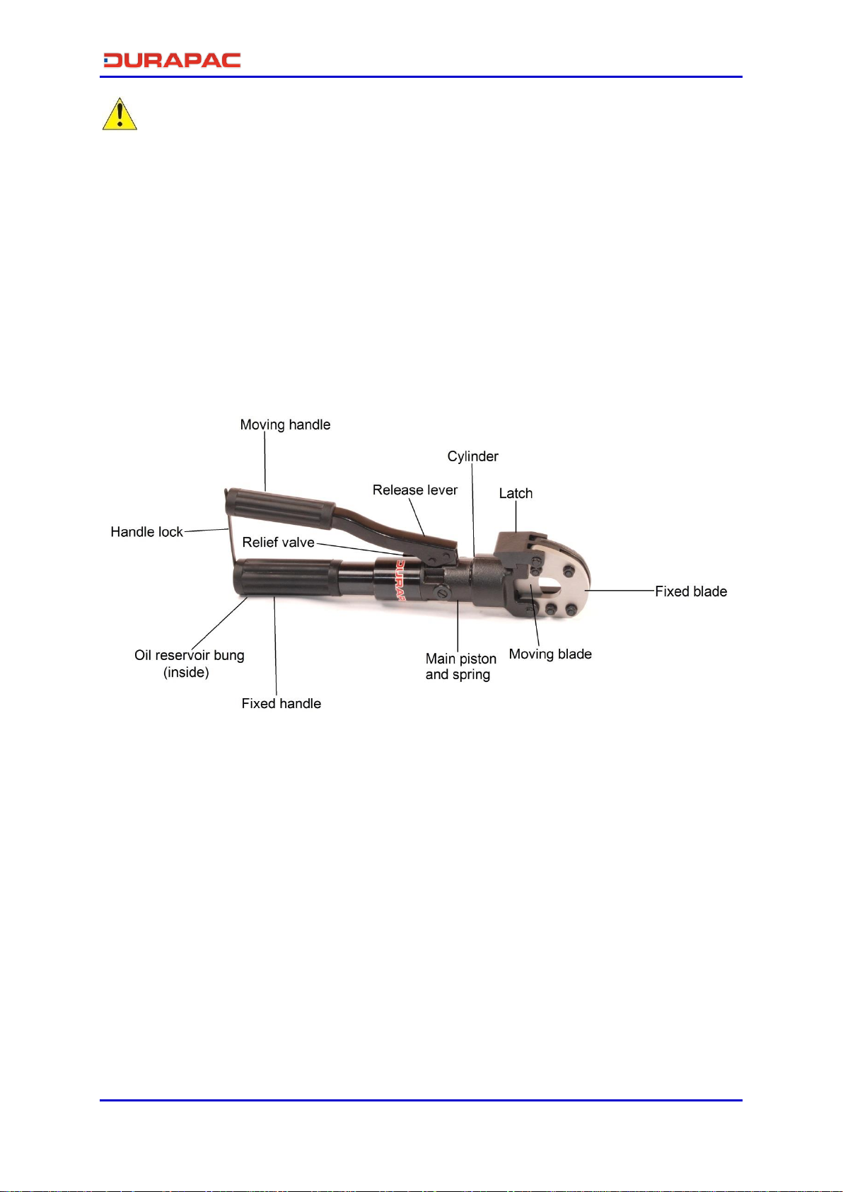
Figure 1 –HC-24S Subassembly
Special skill, knowledge and training may be required for a specific task and the product may not be
suitable for all jobs. The user must ultimately make the decision regarding suitability of the product
for any given task and assume the responsibility of safety for all in the work area. Contact a Durapac
representative if you are unsure of your hydraulic cutter’s suitability for a particular application.
2.0 Receiving Instructions
It is recommended prior to use that an inspection be done by qualified personnel and that any
missing or damaged parts, decals, warning/safety labels or signs are replaced with Durapac
authorised replacement parts only. Any hydraulic cutter that appears to be damaged in any way, is
worn, leaking or operates abnormally should be removed from service immediately until such time
as repairs can be made. Any hydraulic cutter that has been or suspected to have been subject to a
shock load should be removed from service immediately until inspected by a Durapac authorised
service centre. Owners and operators of this equipment should be aware that the use and
subsequent repair of this equipment may require specialised training and knowledge.

Instruction Manual
HC-24S SC Cutter - V1.0 www.durapac.com Page 3 of 9
3.0 Safety
Save these instructions. For your safety, read and understand the information contained within. The
owner and operator should have an understanding of this product and safe operating procedures
before attempting to use this product. Instructions and safety information should be conveyed in the
operator's native language before use of this product is authorised. Make certain that the operator
thoroughly understands the inherent dangers associated with the use and misuse of the product. If
any doubt exists as to the safe and proper use of this product as outlined in this factory authorised
manual, remove from service immediately.
DANGER:
To avoid personal injury keep hands and feet away from work area during operation
WARNING:
Always wear appropriate personal protective equipment (PPE) when operating
hydraulic equipment. The operator must take precaution against injury due to failure
of the tool or work piece(s)
IMPORTANT:
If at any stage, the safety related decals become hard to read, these must be replaced
Minimum age of the operator must be 18 years. The operator must have read and
understood all instructions, safety issues, cautions and warnings before starting to
operate the equipment. The operator is responsible for this activity towards other
persons
Hydraulic equipment must only be serviced by a qualified hydraulic technician. For
repair service, contact the Durapac authorised service centre in your area. To protect
your warranty, use only high quality hydraulic oil
CAUTION:
KEEP HYDRAULIC EQUIPMENT AWAY FROM FLAMES AND HEAT. Hydraulic fluid can
ignite and burn. Excessive heat will soften packings and seals, resulting in fluid leaks.
Heat also weakens hose materials and packings. For optimum performance do not
expose equipment to temperatures of 65°C (150°F) or higher. Protect all equipment
from weld spatter
No alteration should be made to this device
3.1 Hydraulic Cutters
Keep hands off the cutting head section while operating the product
This product is NOT an insulator. Proper equipment should be used to avoid electrical
shock
Do NOT keep this product in places with high temperatures, high humidity or direct
sunlight
Suggested working temperatures -10°C to 40°C

Instruction Manual
HC-24S SC Cutter - V1.0 www.durapac.com Page 4 of 9
Hydraulic fluid temperatures over 65°C might cause damage to components sealed
inside the product
FAILURE TO HEED THESE WARNINGS MAY RESULT IN PERSONAL INJURY AS WELL AS PROPERTY DAMAGE.
4.0 Installation
4.1 Familiarise yourself with the specifications and illustrations in this owner’s manual.
Know your hydraulic cutter, its limitations and how it operates before attempting to
use. Refer to the specification table below or if in doubt, contact a Durapac
representative.
4.2 Check oil level in reservoir before operating cutter.
4.3 Remove air from the system –Air can accumulate in the hydraulic system during the
initial setup or after prolonged use, causing the cylinder to respond slowly or in an
unstable manner. Should removal of air from the hydraulic cutter be required, please
follow the steps in 6.3 –Bleeding Air from the System in the Maintenance Section.
5.0 Operation
IMPORTANT:
The maximum cutting capacity of this tool includes the thickness of the cable covering.
Keep this in mind when selecting the appropriate cable to use. If in doubt, use another
tool to cut away the cable covering before commencing cutting with this tool
Only attempt to cut cables which fit the tool specifications. No other materials are to
be cut
5.1 Before Operation
5.1.1 Make sure all parts of the product are clean, without rust or loose parts.
5.1.2 Check that no leakage occurs while the tool is resting or while the product is
being tested without cables.
5.2 Operation
Stop operating immediately in the case of any abnormalities
5.2.1 Release the hydraulic fluid pressure and retract the piston before opening
the tool head. To release the pressure; press the relief valve lever on the
body at the base of the hydraulic cylinder. Once the piston returns to its
starting position the product is ready to operate.
6x7
(mm)
6x12
(mm)
6x19
(mm)
1x7
(mm)
1x19
(mm)
18 24 24 20 16 24 24 24 16 16 700 56 6.7 28.0 4.0
Guy Wire
Max.
Pressure
(bar)
Oil
Required
(cc)
Max.
Output
(ton)
Cylinder
Stroke
(mm)
Weight
(kg)
Wire Rope
Soft
Steel Bar
(mm)
Reinforcing
Rod (mm)
Copper
Cable
(mm)
Aluminium
Cable
(mm)
ACSR
(mm)

Instruction Manual
HC-24S SC Cutter - V1.0 www.durapac.com Page 5 of 9
5.2.2 Lift the cutting head yoke latch and tilt back the upper blade to open the
cutting head.
5.2.3 Place the cable between the blades at the desired cutting point. Close the
cutter head and close the latch.
5.2.4 Position the cable at the centre of the fixed blade. Improper positioning of
the cable on the edge might cause damage to the blade or deform the tool.
5.2.5 Pump the moving handle back and forth to advance the piston and sliding
blade forward.
5.2.6 Keep pumping the moving handle until the cable is cut.
5.2.7 Press the release valve lever to release the pressure and return the moving
blade to its starting position.
5.2.8 Repeat steps 5.2.2 –5.2.7 until the cutting operation is complete.
5.3 After Operation
5.3.1 Clean the product and blades.
6.0 Maintenance
IMPORTANT:
Check oil level regularly and make sure the reservoir is full
Use only good quality hydraulic fluid. Do NOT use brake fluid, transmission fluid,
turbine oil, motor oil, alcohol, glycerine etc. Use of anything other than good quality
hydraulic oil will void warranty and damage the cutter. We recommend Durapac
Hydraulic Oil or equivalent
Equipment must only be serviced by a qualified hydraulic technician. For repair service,
contact your local Durapac authorised service centre
Tools with worn or damaged blades may cause property damage or even personal
injury
The hydraulic relief valve pressure should only be adjusted by a Durapac
representative
Maintenance is required when wear or leakage is noticed. Periodically inspect all
components to detect any problem that may require service and maintenance.
Keep the tool head free of dirt and metal chips. Use a lubricant to clean the tool when
necessary.
Routine application of rust preventative oil to the product is needed. Avoid bringing the tool
into contact with water or solvents.

Instruction Manual
HC-24S SC Cutter - V1.0 www.durapac.com Page 6 of 9
6.1 Blade Replacement
6.1.1 Fixed Blade Replacement
6.1.1.1 Open the tool head and pull back the fixed blade. Remove the hinge
pin and the four hex nuts to unfasten the blade.
6.1.1.2 Position the new blade, reassemble the hinge pin and screws.
6.1.1.3 Ensure that all components are tight and that the blade opens and
closes smoothly.
6.1.2 Moving Blade Replacement
6.1.2.1 Advance the lower blade until the locating screw is accessible.
6.1.2.2 With the tool head open, use a flat screwdriver to remove the
locating screw to unfasten the blade.
6.1.2.3 Insert the new blade with the sharp edge facing inward. Reassemble
the locating screw to secure the blade in place.
6.1.2.4 Ensure that all components are tight and the blade moves back and
forth smoothly.
6.2 Adding Hydraulic Fluid
6.2.1 Position the tool upside-down in a vice with the pump handle in the open
position.
6.2.2 Unscrew the main handle from the body and then remove the oil reservoir
cap.
6.2.3 Use a small funnel to fill the reservoir to the top of the oil filler hole.
6.2.4 Bleed air from the system (below)
6.2.5 Close the rubber reservoir, insert the filler cap and reassemble the main
handle.
6.3 Bleeding Air from the System
6.3.1 Repeat Steps 6.2.1 to 6.2.3 (above), if required.
6.3.2 Pump the moving handle a few times to advance the cylinder.
6.3.3 Press the release lever to release the pressure in the hydraulic circuit until the
cylinder is fully retracted and the oil has returned completely into the
reservoir.
6.3.4 Repeat the process several times to ensure that all air bubbles are removed.
6.3.5 Recheck oil level after removing air.

Instruction Manual
HC-24S SC Cutter - V1.0 www.durapac.com Page 7 of 9
6.4 Changing Hydraulic Fluid
For best results, change fluid once a year or every 300 hours of use
6.4.1 Repeat Steps 6.2.1 to 6.2.2 (above).
6.4.2 Pour used fluid into a sealable container.
6.4.3 Repeat Steps 6.2.3 to 6.2.5 (above).
6.4.4 Dispose of fluid in accordance with local regulations.
6.5 Storage
6.5.1 Check to ensure that all pieces are in good working condition.
6.5.2 Apply rust preventive oil to the product and blades before returning to the
carrying case.
7.0 Troubleshooting
Problem
Cause
Solution
Cable cannot be cut
Worn or damaged blades
Replace blades
Cables are over specification
Use tool that is appropriate
for cutting requirements
Internal leakage
Send to a Durapac
authorised service centre
for repair
Handle is jammed or unable to
rotate to release pressure
Foreign objects preventing
movement
Clean the moving handle to
remove impediments
Cylinder is loaded at end of
stroke
Pressure can be released by
pressing down the release
lever manually
Torsional spring is damaged
Send to a Durapac
authorised service centre
for repair
Sliding blade is jammed or
unable to retract after
operation
Worn or damaged blades
Replace blades
Blade guide pieces are blocked
with impediments
Use an airgun to remove
impediments
Use lubricant to clean the
tool
Lower blade does not advance
or advances slowly
Air in the hydraulic system
Refer to 6.3 –Bleeding Air
from the System

Instruction Manual
HC-24S SC Cutter - V1.0 www.durapac.com Page 8 of 9
8.0 Parts Breakdown and List

Instruction Manual
HC-24S SC Cutter - V1.0 www.durapac.com Page 9 of 9
Item Description Qty Item Description Qty
1 Latch 1 33 Pump handle 1
2 Compression spring 1 34 Handle grip 1
3 Fixed blade 1 35 Release lever 1
4 Blade guide piece 1 38 Release valve stem 1
5 Blade guide piece 1 39 O-ring 1
6 Stud bolt 4 40 Compression spring 1
7 Hex. nut 8 41 Ball 2
8 Hinge pin 2 42 Compression spring 1
9 Crescent 2 43 Valve screw 1
10 Flat washer 8 44 O-ring 1
11 Moving blade 1 45 O-ring 1
12 Locating screw 1 46 Back-up ring 1
13 Cylinder cover 1 47 O-ring 1
14 Compression spring 1 48 Relief valve set 1
15 Main piston 1 49 Copper washer 1
16 Screw 1 50 Ball 1
17 Stop collar 1 51 Compression spring 1
18 Back-up ring 1 52 Solid filter 1
19 O-ring 1 53 Oil screen 1
20 Pin 2 54 Oil reservoir 1
22 Cylinder body 1 55 Filler cap 1
24 Compression spring 1 55-2 Magnetic bar 1
25 Valve screw 1 56 Extension tube 1
26 Torsional spring 1 57 Spring pin 1
27 O-ring 1 58 Fibre glass pipe 1
28 Back-up ring 1 59 Handle grip 1
29 Dust seal 1 60 Holding band 1
30 Pump piston 1 62 Screen holder 1
31 Hinge pin 2 63 Spring pin 1
32 Crescent 4
Serial number and model need to be quoted when ordering parts.
Table of contents
Other Durapac Cutter manuals
Popular Cutter manuals by other brands

Scantool
Scantool SCS Series manual

Koike Sanso Kogyo
Koike Sanso Kogyo EDGE-CUT Operation manual

Bergeon
Bergeon 6580-2000 quick start guide

Rothenberger
Rothenberger SUPERTRONIC 2 SE Instructions for use

EINHELL
EINHELL bavaria BMF 1300 operating manual

KRUG+PRIESTER
KRUG+PRIESTER EBA 4855 operating instructions