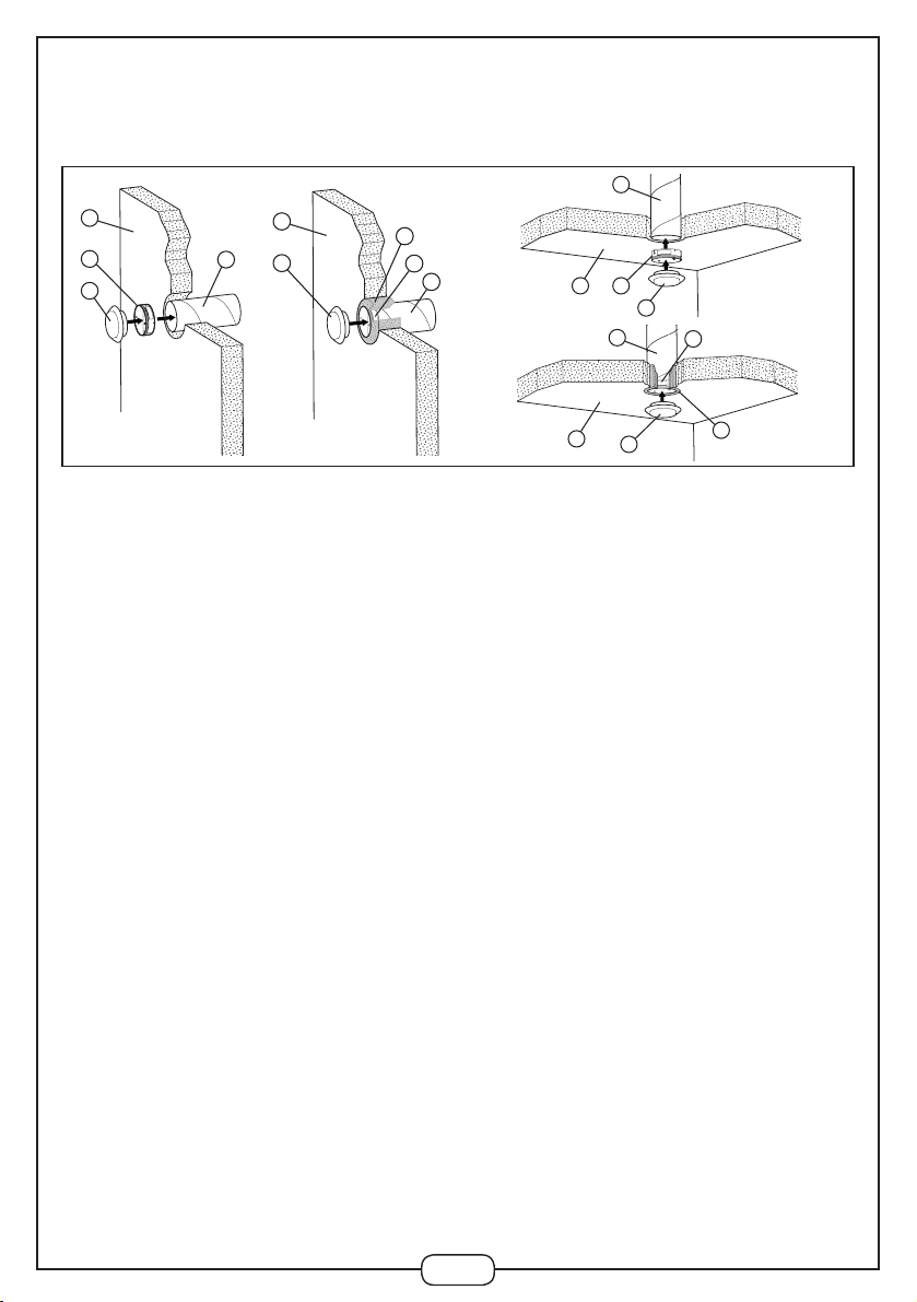
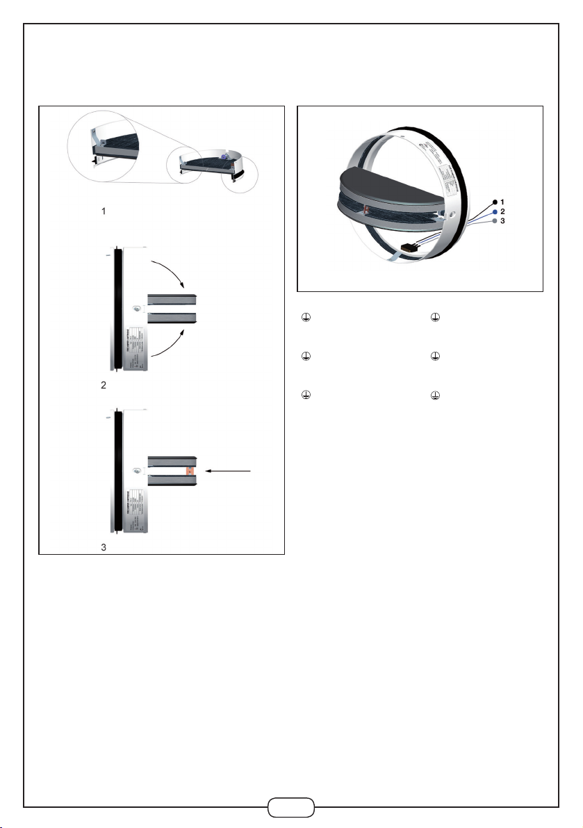
aldes CF1 User manual

CF1 - CF2
1396 - CPD - 0055
www.aldes.com
Aldes CF1-CF2 - ind E
GB
Original Installation, Operation and Maintenance manual
Terminal fire Damper
DE
Die original Anleitung für Installation, Betrieb und Kontrolle
Endseitige Brandschutzklappe
FR
Manuel original d’installation, d’exploitation et de contrôle
Clapet terminal coupe-feu
NL
Originele Installatie-, Bedienings- en Onderhoudsvoorschriften
Eindklep voor brandgevel
IT
Manuale originale di installazione, uso e manutenzione
Serranda tagliafuoco terminale
ES
Manual original de instalación, uso y mantenimiento
Válvula terminal cortafuego
Notice de Montage


3
GB
Conformities
DE
Abweichungen
12 1396
1396 - CPD - 0055
EN 15650 : 2010
12 1396
1396 - CPD - 0055
EN 15650 : 2010
Fire damper cartridge:
CF1 El 60S Ø 100 -200 ZV-DV1
CF2 EI120S Ø 100 -200 ZV-DV1
Brandschutzklappe:
CF1 El 60S Ø 100 -200 ZV-DV1
CF2 EI120S Ø 100 -200 ZV-DV1
Nominal activation Pass
Conditions / sensitivity:
- Sensing element load bearing capacity
- Sensing element response temperature
Response delay (response time) Pass
- Closure time
La fiabilité de fonctionnement :
- Cyclisme 50 cycles pass
Operational reliability
- Maintenance of the cross section (under E)
- Integrity E EI60/1 20 (ve ho i o) S
- lnsulation I
- Smoke leakage S
- Mechanical stability (under E)
- Cross-section (under E)
Durability of response delay
- Sensing element response temperature and load bearing capacity Pass
Durability of operational reliability
- Open and closing cycle Pass
Nominale Aktivierung Erfüllt
Nennbedingungen der Aktivierung / Empfindlichkeit:
- Belastbarkeit des temperaturempfindlichen Messfühlers
- Ansprechtemperatur des temperaturempfindlichen Messfühlers
Ansprechverzögerung (Ansprechzeit) Erfüllt
- Temps de fermeture
Betriebssicherheit
- Zyklische Prüfung 50 Zyklen - erfüllt
Feuerwiderstand:
- Beibehaltung des Querschnitts (bzgl. E)
- Raumabschluss E EI60/1 20 (ve ho i o) S
- Wärmedämmung I
- Rauchleckage S
- Mechanische Festigkeit (unter E)
- Querschnitt (unter E)
Ansprechzeit
- Ansprechen des temperaturempfindlichen Messfühlers auf Temperatur und Belastbarkeit Erfüllt
Dauerhaftigkeit der Betriebssicherheit
- Prüfungen des Öffnungs - und Schließzyklus Erfüllt

4
FR
Conformités
12 1396
1396 - CPD - 0055
EN 15650 : 2010
Cartouche coupe-feu :
CF1 El 60S Ø 100 -200 ZV-DV1
CF2 EI120S Ø 100 -200 ZV-DV1
Activation nominale Passés
Conditions / sensibilité :
- Elément de détection de charge capacité portante
- Détection de température élément de réponse
Délai de réponse (temps resp.) Passés
- Temps de fermeture
La fiabilité de fonctionnement
- Cyclisme 50 cycles passés
Résistance au feu
- L’entretien de la section transversale (sous E)
- L’intégrité E EI60/1 20 (ve ho i o) S
- lsolation I
- Etanchéité à la fumée S
- Stabilité mécanique (sous E)
- Section (sous E)
Temps de réponse
- Détection de température élément de réponse et la charge portant col capacité Passés
Durabilité de la fiabilité opérationnelle
- Cycle ouvert et la fermeture Passés
NL
Nakoming
12 1396
1396 - CPD - 0055
EN 15650 : 2010
Brandkleppatroon:
CF1 El 60S Ø 100 -200 ZV-DV1
CF2 EI120S Ø 100 -200 ZV-DV1
Nominale activerings Conform
omstandigheden/gevoeligheid:
- Belastbaarheid meetsonde
- Aanspreektemperatuur meetsonde
Responstijd (reactietijd) Conform
- Sluittijd
Betrouwbare werking
- Cyclische testen 50 cycli - conform
Brandweerstand
- Instandhouding van de doorvoering (in E)
- Vlamdichtheid E EI60/1 20 (ve ho i o) S
- Thermische isolatie I
- Rookdoorlatendheid S
- Mechanische stabiliteit (in E)
- Vrije doorlaat (in E)
Reactietijd
- Belastbaarheid en aanspreektemperatuur van de meetsonde Conform
Duurzaamheid van de bedrijfszekerheid
- Open- en sluitcyclus Conform

5
IT
Conformità
12 1396
1396 - CPD - 0055
EN 15650 : 2010
Cartuccia tagliafuoco:
CF1 El 60S Ø 100 -200 ZV-DV1
CF2 EI120S Ø 100 -200 ZV-DV1
Attivazione normale Conforme
Condizioni / sensibilità:
- Elementi di rilevamento di carico capacità portante
- Rilevamento di temperatura elemento di risposta
Tempo di risposta (tempo risp.) Conforme
- Tempo di chiusura
Affidabilità del funzionamento
- Ciclicità 50 cicli - conformi
Resistenza al fuoco
- La manutenzione della sezione trasversale (sotto E)
- L’integrità E EI60/1 20 (ve ho i o) S
- Isolamento I
- Tenuta al fumo S
- Stabilità meccanica (sotto E)
- Sezione (sotto E)
Tempo di risposta
- Rilevamento di temperatura elemento di risposta e carico portante collo capacità conforme Conforme
Durabilità dell’affidabilità operativa
- Ciclo aperto e chiusura Conforme
ES
Conformidad
12 1396
1396 - CPD - 0055
EN 15650 : 2010
Cartucho cortafuego:
CF1 El 60S Ø 100 -200 ZV-DV1
CF2 EI120S Ø 100 -200 ZV-DV1
Activación nominal Confirme
Condiciones/sensibilidad:
- Elementos de detección de carga capacidad portante
- Detección de temperatura elemento de respuesta
Plazo de respuesta (tiempo de resp.) Confirme
- Tiempo de cierre
La fiabilidad de funcionamiento
- Ciclismo 50 ciclos – conforme
Resistencia al fuego
- El mantenimiento de la sección transversal (en E)
- La integridad E EI60/1 20 (ve ho i o) S
- Aislamiento I
- Estanqueidad al humo S
- Estabilidad mecánica (en E)
- Sección (en E)
Tiempo de respuesta
- Detección de temperatura elemento de respuesta y la carga portante cuello capacidad Confirme
Durabilidad de la fiabilidad operacional
- Ciclo abierto y el cierre Confirme

6
Installation
CF1 - CF2
1 - Wall, 2 - Gypsum / Mortar/ Concrete, 3 - Steel duct, 4 - CF1 - CF2, 5 - Disc valve
1 - Decke, 2 - Gips / Mörtel / Beton, 3 - Stahlrohr, 4 - CF1 - CF2, 5 - Ventil
1 - Paroi, 2 - Plâtre / Mortier / Béton, 3 - Gaine acier, 4 - CF1 - CF2, 5 - Bouche ventilation
1 - Plafond, 2 - Gips, 3 - Stalen kanaal, 4 - CF1 - CF2, 5 - Ventiel
1 - Parete, 2 - Gesso / Malta / Cemento, 3 - Condotto in acciaio, 4 - CF1 - CF2, 5 -Valvola
1 - Pared, 2 - Yeso / Mortero / Hormigón, 3 - Conducto metálico, 4 - CF1 - CF2, 5 -
Boca de ventilación
Fig.1 Embedding of the terminal fire damper using gypsum/mortar/concrete
Abb. 1 Installation einer Endseitige Brandschutzklappe mit Gips/Mörtel/Beton
Fig.1. Scellement d’un clapet terminal coupe-feu à l’aide du plâtre/mortier/béton
Fig.1 Afwerking van de eindklep voor brandgevel met gips, specie of beton
Fig.1 Inserimento della serranda tagliafuoco terminale con gesso/malta/cemento
Fig.1 Sellado de una válvula terminal cortafuego con yeso/mortero/hormigón
1 - Ceiling, 2 - Gypsum, 3 - Steel duct, 4 - CF1 - CF2, 5 - Disc valve
1 - Die Mauer, 2 - Gips / Mörtel / Beton, 3 - Stahlrohr, 4 - CF1 - CF2, 5 - Ventil
1 - Plafond, 2 - Plâtre / mortier / béton, 3 - Gaine acier, 4 - CF1 - CF2, 5 - Bouche
ventilation
1 - Wand, 2 - Gips/specie/beton, 3 - Stalen kanaal, 4 - CF1 - CF2, 5 - Ventiel
1 - Soffito, 2 - Gesso, 3 - Condotto in acciaio, 4 - CF1 - CF2, 5 - Valvola
1- Techo, 2 - Yeso / Mortero / Hormigón, 3 - Conducto metálico, 4 - CF1 - CF2,
5 - Boca de ventilación
5
4
1
35
1
3
4
2
1 4
3
5
1
34
2
5
Fig.1

7
Installation
1 - Disc valve, 2 - CF1 - CF2, 3 - Gypsum, 4 - Duct
1 - Ventil, 2 - CF1 - CF2, 3 - Gips, 4 - Rohrleitung
1 - Bouche ventilation, 2 - CF1 - CF2, 3 - Plâtre, 4 - Conduiteventilation
1 - Ventiel, 2 - CF1 - CF2, 3 - Gips, 4 - Kanaal
1 - valvola, 2 - CF1 - CF2, 3 - gesso, 4 - condotto
1 - Boca de ventilación, 2 - CF1 - CF2, 3 - Yeso, 4 - Conducto
Fig.2 Installation into the End of a Duct with a Valve
Abb. 2 Installieren Sie das Ende des Rohres mit einem Ventil
Fig.2 Montage d’un clapet terminal coupe-feu au bout de la gaine munie
d’une bouche ventilation
Fig.2 Installatie in het uiteinde van een kanaal met behulp van een ventiel
Fig.2 Installazione a fine condotto con una valvola
Fig.2 Instalación en el extremo de un conducto provisto de una boca de
ventilación
Fig.3 Installation of a terminal fire damper using mineral wool and cover
plates
Abb.3 Montage einer Endseitige Brandschutzklappe mit Hilfe von
Mineralwolle mit Abdeckung
Fig.3 Montage d’un clapet terminal coupe-feu à l’aide de la laine minérale
avec plaques de couverture
Fig.3 Montage van een eindklep voor brandgevel met behulp van minerale
wol met afdekplaten
Fig.3 Montaggio di una serranda tagliafuoco terminale mediante lana
minerale con piastre di copertura
Fig.3 Montaje de una válvula terminal cortafuego con lana mineral con
placas de cobertura
Fig.4 Installation of a terminal fire damper using mineral wool without
cover plates
Abb.4 Montage einer Endseitige Brandschutzklappe mit Hilfe von
Mineralwolle ohne Abdeckung
Fig.4 Montage d’un clapet terminal coupe-feu à l’aide de la laine minérale
sans plaques de couverture
Fig.4 Montage van een eindklep voor brandgevel met behulp van minerale
wol zonder afdekplaten
Fig.4 Montaggio di una serranda tagliafuoco terminale mediante lana
minerale senza piastre di copertura
Fig.4 Montaje de una válvula terminal cortafuego con lana mineral sin
placas de cobertura
1 - CF1 - CF2, 2 - Cover plates, 3 - Mineral wool with a minimum density of 50-100 kg.m-3, 4 - Steel pipe, 5 - Disk valve, 6 - Plasterboard wall, 7 - Mineral wool, 8 - Horizontal profile
UW, 9 - Vertical profile CW
1 - CF1 - CF2, 2 - Deckplatten, 3 - Mineralwolle mit min. Dichte von 50 bis 100 kg/m3, 4 - Stahlrohr, 5 - Ventil, 6 - Gipskartonwände, 7 - Mineralwolle, 8 - Horizontal Profil UW,
9 - Vertikal-Profil CW
1 - CF1 - CF2, 2 - Plaques de couverture, 3 - Laine minérale de densité minimale de 50-100 kg.m-3, 4 - Gaine acier, 5 - Bouche ventilation, 6 - Cloison en placoplâtre, 7 - Laine
minérale, 8 - Profilé horizontal UW, 9 - Profilé vertical CW
1 - CF1 - CF2, 2 - Afdekplaten, 3 - Minerale wol met een minimale dichtheid van 50-100 kg.m-3, 4 - Stalen kanaal, 5 - Ventiel, 6 - Wand van gipsplaat, 7 - Minerale wol, 8 - Horizontaal
profiel UW, 9 - Verticaal profiel CW
1 - CF1 - CF2, 2 - Lastre di copertura, 3 - Lana minerale con densità minima di 50-100 kg.m-3, 4 - condotto in acciaio, 5 - Valvola, 6 - Parete in cartongesso, 7 - Lana minerale,
8 - Profilato orizzontale UW, 9 - Profilato verticale CW
1 - CF1 - CF2, 2 - Placa de recubrimiento 3 - Lana mineral con densidad mínima de 50-100 kg/m3, 4 - Conducto acero, 5 - Boca de ventilación, 6 - Tabique de pladur, 7 - Lana mineral,
8 - Perfil horizontal UW, 9 - Perfil vertical CW.
51
4
69
8
7
5
1
4
69
8
7
3
51
2
2
4
3
69
8
7
5
1
2
24
69
8
7
3
CF1 - CF2
Fig.2
Fig.3 Fig.4

8
1 - Press bath detent springs, 2 - Open the blades into a parallel position, 3 - Put on the
thermal fuse link
1 - Drücken die beiden Arretierfedern, 2 - Offnen Briefe an die parallele Position,
3 - Dritte Ersetzen Sie die Thermosicherung
1 - Poussez deux ressorts de détente, 2 - Mettez les lames en position horizontale,
3 - Insérez le fusible thermique
1 - Druk beide palveren in, 2 - Open de bladen in een parallel positie, 3 - Plaats de
thermische smeltlood
1 - Sbloccare entrambe le molle di arresto, 2 - Aprire le alette in posizione parallela,
3 - Inserire il fusibile
1 - Empujar los 2 muelles de disparo, 2 – Poner las lamas en posición horizontal,
3 - Insertar el fusible térmico
Fig.5 Adjusting the terminal fire damper into Opera ting Position
Abb. 5 Stellung der Endseitige Brandschutzklappe in die geoffnete Position
Fig.5 Réarmement d’un clapet terminal coupe-feu
Fig.5 lnstellen van de eindklep voor brandgevel in de definitieve positie
Fig.5 Regolazione della serranda tagliafuoco terminale in posizione di funzionamento
Fig.5 Rearme del válvula terminal cortafuego
Fig.6 Connection of the end switch
Abb. 6 Beteiligung der Endschalter
Fig.6 Branchement d’un interrupteur fin de course
Fig.6 Aansluiten van de eindschakelaar
Fig.6 Collegamento del finecorsa
Fig.6 Conexión de un contacto final de carrera.
1 -black wire 1 -zwarte draad
2 CLOSED indicator -blue wire 2 GESLOTEN indicator -blauwe draad
3 OPEN indicator -grey wire 3 OPEN indicator -grijze draad
1 -schwarzer Kabel 1 -terra fila nera
2 Anzeige GESCHLOSSEN -blauer Kabel 2 segnalazione di chiusura -fila blu
3 Anzeige GEOFFNET -grau er Kabel 3 segnalazione di apertura -fila grigio
1 -fil noir 1 -cable negro
2 Indication de position FERMÉ -fil bleu 2 Indicación de posición CERRADO -cable azul
3 Indication de position OUVERT -fil gris 3 indicación de posición ABIERTO -cable gris
Activation
CF1 - CF2
Fig.5
Fig.6

9
Introduction
The Installation, Operation and Maintenance manual applies to the terminal fire damper types CF1 – CF2, EI60S,
EI120S, contains basic information and recommendations regarding the design, installation and usage, which need to
be followed in order to guarantee a proper and trouble-free operation of the unit. The key to this is to read this manual
thoroughly, use the damper according to the instructions provided in it and to adhere to the safety requirements.
Contents
Figures.............................................................................................................................................................................................................................................................................................................................................6
Introduction........................................................................................................................................................................................................................................................................................................................... 9
Contents.......................................................................................................................................................................................................................................................................................................................................9
Warning.........................................................................................................................................................................................................................................................................................................................................9
Operation................................................................................................................................................................................................................................................................................................................................... 9
1 Installation Manual............................................................................................................................................................................................................................................................................................ 10
2 Operation Manual............................................................................................................................................................................................................................................................................................... 11
3 Maintenance and Inspection Manual................................................................................................................................................................................................................................... 11
Technical details........................................................................................................................................................................................................................................................................................................ 12
Identification and certification............................................................................................................................................................................................................................................................. 33
Warning
Some of the fire damper parts might have sharp edges – therefore it is necessary to use gloves during the installation
and usage of the damper.
In order to avoid electrical shock, fire or other damage that might occur as a result of incorrect usage and operation
of the unit, it is important to comply with the following principles:
• It is necessary to install the system according to the Installation manual.
• It is necessary to perform the fire damper check according to the manual.
Operation
General Information
The terminal fire dampers are defined as fire closures for ventilation ducts, to be installed in the spot where the
ventilation duct passes through the fire partition wall, or at the end of the duct in front of the outlet. In case of a fire
dampers work as a fire safety element and prevent the fire from spreading throughout the ventilation duct during a
specified amount of time.
• All the units are actuated by springs.
• Additional accessories, such as flexible couplings, disk valves etc., can be ordered separately.
• The accessories are supplied separately and demounted, ready to be mounted on site by the responsible staff.
The dampers are to be operated in a workplace which is protected from weather conditions and to be used in
ventilation ducts distributing the air without any other mechanic or chemical contamination in the following
operating conditions:
• The maximum air flow speed of 12m/s.
• The maximum relative air humidity of 90%.
• The temperature falling within the range of -10 to +65°C.
In terms of noise, the fire dampers are passive. Increased noisiness only occurs while the damper is being opened or
closed as a result of inspection or fire, which should not last longer than 5 seconds.
As a standard, all the terminal fire dampers are equipped with a thermal fuse link, which, after having reached or
exceeded the temperature of 72°C with a ± 1,5°C tolerance, unblocks the actuating springs, which causes the damper
blades to close.
Terminal Fire Damper
English

10
Terminal Fire Damper
1 Installation Manual
• The terminal fire dampers are installed into the duct, either in the place where the fire-proof wall is, or at the end
of the duct in front of an air valve or a similar outlet. (The terminal fir dampers are installed into the duct, either
in the place where the fire-proof wall is into a transversal duct, or at the end of the duct in front of an air valve or
a similar outlet.)
• The pitch between the ducts and the fire dampers must be at least 200 mm, according to the EN 1366-2 regulation.
• According to the EN 1366-2 regulation, there must be at least a 75 mm gap between the wall and the ductwork with
the fire damper.
• The fire damper is embedded into the fire partition construction pipe in such a way that when the damper blades
are in the CLOSE position, they will be entirely situated inside the wall.
• The damper can be embedded into a wall or a ceiling with a minimum thickness according to the EN 1366-2
regulation for the respective fire resistance class.
• All the dampers can be installed with a horizontal or a vertical blade axis.
1.1 Embedding the CF1 - CF2 into a Wall /
Ceiling Using Gypsum, Mortar or Concrete – Wet Installation (see Fig.1)
1. For installation purposes, make a round opening with a minimum diameter of ød + 60 mm into the wall.
2. Insert the duct inside the middle of the opening.
3. Fill in the space between the wall and the pipe with the gypsum, mortar or concrete, while paying special attention
to not contaminate the inside of the pipe.
4. Insert the fire damper into the pipe and ensure that the whole blade of the closed damper is situated within the wall.
5. Check the damper’s functionality (see the Operation manual).
1.2 Installation Into the End of a Duct with a Valve (see Fig.2)
CF1 - CF2 can be installed into a wall/ceiling at the end of a duct with a disc valve (the valve needs to be separately
ordered from the ADP catalogue – an advisable type would be the plastic valve “Balance-E” from Systemair AB,
Sweden). The installation is the same as described in section 1.1, remembering that the end of the duct must stay in
allignment with the side of the wall/ceiling where the valve is going to come. When attaching the CF1 - CF2, the area
where its leaves will be inclining after the closure needs to be placed at a distance of 50±10mm from the duct end.
The CF1 - CF2 damper leaves must open in the direction into the duct.
1.3 Embedding the CF1 - CF2 into a Wall Using Mineral Wool –
Dry Installation (see Fig.3 and 4)
1. For installation purposes, make a round opening with a minimum diameter of ød + 60 mm into the wall.
2. Insert the pipe inside the middle of the opening.
3. Attach the cover plates to the wall around one side of the pipe.
4. Fill in the space between the wall and the pipe with mineral wool, while paying special attention to not contaminate
the inside of the pipe.
5. Attach the cover plates to the wall around the other side of the pipe.
6. Insert the fire damper into the pipe and ensure that the whole blade of the closed damper is situated within the wall.
7. Check the damper‘s functionality (see the Operation manual).
COVER PLATES ARE MANDATORY WHEN PERFORMING A DRY INSTALLATION!
1.4 Adjusting the Damper into Operating Position (see Fig.5)
1. Press both detent springs.
2. Open the blades into a parallel position.
3. Put on the thermal fuse link.

11
Terminal Fire Damper
2 Operation Manual
The terminal fire damper is ready for use when its blades are open according to chapter 1.3 adjusting the Damper
into Operating Position. The blade position, if using a DV1 version, is indicated by an end switch, which indicates the
damper blades’ open and closed position. The microswitch contains three isolated wires (see Fig.5) which need to
be led out of the duct through a hole drilled in the pipe as close to the microswitch as possible and near the wall, the
hole being secured with a rubber grommet.
3 Maintenance and Inspection Manual
The actuating mechanism keeps the dampers on stand-by mode throughout their entire operational life. Without
the producer’s permission, there must be no changes or modifications performed on the damper’s structure. The
operator executes regular damper checks according to the local laws and regulations. Unless stated otherwise, the
operator checks the damper every 12 months.
CF1 - CF2 is checked visually after having removed the disc valve from the duct end. If the damper is installed in a
duct crossing a fire-proof wall, to access the damper it is needed to disjoin the duct pipe near the wall, on the side
where the damper blades open. For this purpose it is convenient to use a flexible coupling during installation which
facilitates the access inside the damper.
It is needed to check the damper’s internal casing, the thermal fuse link, the sealing, the foaming substance, the
damper blade’s condition and its closure while it leads to a backstop in a closed position. There must be no other
objects or dirt from the ventilation duct inside the damper. While performing the check we also focus on the thermal
fuse link’s integrity and a correct position of the damper blades after their detention in the OPEN position – they
should be roughly parallel to the longitudinal axis of the duct.
We perform the damper activity check by taking off the thermal fuse link and releasing the blades to spontaneously
close themselves – the damper blades are closed by a spring return release. The damper must be completely closed –
the blades must fall behind the detent springs. If using the DV1 version, the blade’s position is indicated by a
connection of the respective circuit shown on Fig.3. After having checked that the sealing is intact and abuts against
the whole perimeter of the blade to the damper body, we open the blades again and detent those in the OPEN position
using the thermal fuse link. When opening the blades it is first needed to push the detent spring and use the hook
attached to the opening of the thermal fuse link’s holder to open the blade. Before opening the second blade it is
possible to secure the first blade in the OPEN position by inserting an appropriate object between the blade and the
damper body (this object must be removed after the thermal fuse link is put on).
In case of bad access when checking the damper functionality by a complete closure of the blades (the damper is
too small, the duct pipe in the wall is too long...) it is possible to detach the damper from the duct. We can do so by
either pulling it out of the duct while holding it by its open blades or it is needed to disjoin the pipe on the other side
of the wall as well and push the damper out of the duct. If using an end switch signalizing the damper blades’ closed
position, it is necessary to disconnect the switch wires from the terminal outside of the duct and pull the wires into
the duct before detaching the damper itself. After doing this, it is possible to take the damper out of the duct. When
remounting the damper into the duct it is also essential to check the flexibility of the draft seal on the perimeter and
in case it shows permanent deformation, it is needed to replace the seal by a new one in order to guarantee a correct
fixation of the damper in the duct.
Recommended Check Steps According to the EN 15 650 Regulation
1. Date of inspection.
2. Check of the end switch’s connection for damage if applicable.
3. Check for damper cleanliness and cleaning if needed.
4. Check of the blades and sealing, correction.
5. Check of fire damper’s safe closure - for details please see the previous section.
6. Check if the damper moves while being in its open and closed position, correction.
7. Check of the end switch indicating the open and closed position, correction.
8. Check if the damper is moved in its standard position. The CF1 - CF2 damper’s position is correct when, after the
closure, the blades are in between the planes forming the outside surface of the wall – the ideal position is when
the blade is in the middle between these planes.
3.2.1 Replacement of the Thermal Fuse Link
When replacing the thermal fuse link it is necessary to follow the instructions from 1.3 adjusting the Damper into
Operating Position manual – we take off the thermal fuse link and put on a new one.
English

12
Technical details
Pressure loss
Dimensions (mm) - Weight (kg)
Product reference CF1 CF2 Diagrams
Commercial brand ALDES
Type of product Terminal fire damper Terminal fire damper
Range Ø100 mm to 200 mm Ø100 mm to 200 mm
Fire protection rating EI 60 (ve ho i<->o) S EI 120 (ve ho i<->o) S
Test pressure 300 Pa 300 Pa
Types of wall
Concrete wall Mounted in 100 mm or 150 mm
solid concrete wall
Fire resistance ≥60’
Mounted in 150 mm lightweight
partition wall
Fire resistance ≥120’
See Fig.1
page 3
Lightweight
partition wall
Mounted in 100 mm or 150 mm
lightweight partition wall
Fire resistance ≥60’
Mounted in 150 mm lightweight
partition wall
Fire resistance ≥120’
See Fig.3
and 4
page 4
Concrete slab Mounted in 125 mm solid
concrete slab
Fire resistance ≥60’
Mounted in 150 mm solid
concrete slab
Fire resistance ≥60’
See Fig.1
page 3
Caulking
With mortar or plaster:
- concrete,
- concrete slab,
- lightweight partition.
With Rock wool:
- concrete.
With mortar or plaster:
- concrete - concrete slab,
- lightweight partition,
With Rock wool:
- concrete,
- lightweight partition.
Type of installation
- Fire damper embedded.
- Grille surface-mounted (see Fig.4
page 4)
- Terminal position
- Fire damper embedded.
- Grille surface-mounted with cover
plates each side of partition wall
(see Fig.3 page 4).
- Terminal position.
Electrical details of
position contacts 24V DC/230V AC
microswitch in DV1 version 24V DC/230V AC
microswitch in DV1 version
Ø D
(mm)
Speed in duct (m/s)
2345678910
Q
(m
3
/h)
∆P
(Pa) Q
(m
3
/h)
∆P
(Pa) Q
(m
3
/h)
∆P
(Pa) Q
(m
3
/h)
∆P
(Pa) Q
(m
3
/h)
∆P
(Pa) Q
(m
3
/h)
∆P
(Pa) Q
(m
3
/h)
∆P
(Pa) Q
(m
3
/h)
∆P
(Pa) Q
(m
3
/h)
∆P
(Pa)
100 57 12 85 30 113 50 141 80 170 - 198 - 226 - 254 - 283 -
125 88 6133 12 177 22 221 37 265 50 309 70 353 90 398 - 442 -
140 111 4166 9222 15 277 24 333 34 388 48 443 60 499 80 554 95
150 127 3191 7254 12 318 20 382 27 445 38 509 50 573 60 636 75
160 145 3217 6290 10 362 17 434 22 507 30 579 40 651 50 724 60
180 183 2275 4366 7458 11 550 26 641 20 733 38 824 35 916 40
200 226 1339 3452 5565 8679 12 792 17 905 20 1018 27 1131 30
(mm) d
(mm) EI 60/120 S
W1 (mm)
EI 60 S EI 120 S
Weight (kg)
100 98,5 27 0,3 0,3
125 123,5 39,5 0,4 0,4
150 148,5 52 0,4 0,6
160 158,5 57 0,5 0,6
200 198,5 77 0,7 0,9
Terminal Fire Damper
Ø d
60 W1

13
Einführung
Die Installation, Bedienung und Kontrolle Einleitung betrifft der Endseitige Brandschutzklappen Type CF1 - CF2 EI60S,
EI120S, enthält Grundinformationen und Empfehlungen für die Installation und Verwendung die sind zu beachten für
Störungsfreier Betrieb der Brandsutzklappe. Der Schlüssel zur ordnungsgemäßen und sicheren Betrieb der Einheit ist
bestens Vertrauen mit dieser Anleitung, die Verwendung von Klappen in Übereinstimmung mit den darin enthaltenen
Anweisungen, und die Einhaltung der Sicherheitsanforderungen.
Inhalt
Abbildungen
.......................................................................................................................................................................................................................................................................................................
6
Einführung
........................................................................................................................................................................................................................................................................................................
13
Inhalt
.........................................................................................................................................................................................................................................................................................................................
13
Anmerkung
......................................................................................................................................................................................................................................................................................................
13
Der Betrieb
.......................................................................................................................................................................................................................................................................................................
13
1 Installationsanweisung
..............................................................................................................................................................................................................................................................
14
2 Hinweise zur Benutzung
.........................................................................................................................................................................................................................................................
15
3 Hinweise für Wartung und Revision
......................................................................................................................................................................................................................
16
Technische Informationen
.......................................................................................................................................................................................................................................................... 16
Beschreibung und Zertifizierung
........................................................................................................................................................................................................................................ 33
Anmerkung
Die Kanten von einigen Komponenten von Brandschutzklappen können knackig sein - so ist es notwendig, bei
Installieren und Manipulation Handschuhe zu verwenden.
Um einen elektrischen Schlag, Feuer oder andere Schäden verhindern, die aus fehlerhafter Verwendung und Betrieb
der Einheit führen können, ist es wichtig, die folgenden Grundsätze zu beachten:
• Das System muss nach Installationsanweisungen installiert werden.
• Überprüfen der Brandschutzklappe ist nach der Einleitung zu durchführen.
Betrieb
Allgemeine Informationen
Endseitige Brandschutzklappen sind wie Feuer Verschlüsse bezeichnet für Luftleitungen mit der Installation an
der Stelle, wo das Rohr durch die Brandwand geht oder am Ende des Rohres vor dem Auslass/Ventil. Im Falle des
Brandfall dienen die als Brandschutzeinheit und während einer vorgegebenen Zeitspanne verhindern Durchtritt von
Feuer und Rauch durch den Lüftungskanal.
• Alle Geräte sind durch Federn gesteuert.
• Zubehör wie flexible Kupplungen, Ventile und Deckplatten können separat bestellt werden.
• Zubehör wird separat geliefert und vor Ort von Monteure fertig montiert wird.
Klappen sind so ausgelegt, in einem Umfeld, das von Witterung geschützt ist, um in den Luftrohrleitungen ohne
zusätzliche mechanische oder chemische Zusätze für die folgenden Betriebsbedingungen eingesetzt zu werden und
zu betreiben:
• Die maximale Luftgeschwindigkeit - 12 m/s.
• Maximale relative Luftfeuchtigkeit - 90%.
• Temperaturbereich von -10 bis +65°C.
Endseitige Brandschutzklappen sind passiv in Bezug auf Lärm. Erhöhtes Rauschen ist nur in weniger als 1 Sekunde
auf manifestierte Schließen bei der Überprüfung oder Kontrolle der Brandschutzklappe.
Alle EndseitigeBrandschutzklappen sindmit einer Thermosicherungausgestattet, diebei Erreichen oderÜberschreiten
72°C mit Toleranz von ± 1,5°C entriegelt die Schließfeder und die Blätter der Brandschutzklappen geschlossen werden.
Endseitige Brandschutzklappe
Deutsch

14
Endseitige Brandschutzklappe
1 Installation
• Endseitige Brandschutzklappen sind in der Rohr in den feuerbeständigen Wänden in ein kontinuierliches Rohr oder am
Ende vor das Ventils oder einen ähnlichen Auslass zu installieren.
• Der Abstand zwischen den Rohren mit einer Brandschutzklappe muss in Übereinstimmung mit DIN EN 1366-2 mindestens
200 mm betragen.
• Zwischen der Wand und einer Brandschutzklappe muss in Übereinstimmung mit DIN EN 1366-2 angesehenen Abstand von
75 mm betragen.
• Brandschutzklappe ist das Rohr montiert, so dass, die Blätter der Brandschutzklappe in der geschlossenen Position sind,
müssen die innerhalb der Wand sein.
• Die Klappe muss in den Wand oder in die Decke der minimalen Dicke gemäß DIN EN 1366-2 für die Bestimmte
Feuerwiderstand installiert.
• Alle Endseitige Brandschutzklappen können mit der Achse der Blätter in horizontaler oder vertikaler Lage eingebaut
werden.
1.1 Installation der CF1 - CF2 in die Wand / Decke mit Gips, Mörter oder
Beton Mischungen - Nass - Installation (siehe Abbildung 1)
1. Für den Installation in der Wand rundes Loch mit einem Durchmesser von mindestens ND + 60 mm zu vorbereiten.
2. Die Rohr in die Mitte der Öffnung zu stecken.
3. Der Raum zwischen der Wandöffnung und Brandschutzklappe mit einer Betonmischung, Gips oder Mörtel zu füllen,
wobei Verschmutzung der Innenseite des Rohrs zu vermeiden.
4. Die Brandschutzklappe in die Rohr einzufügen, so dass die ganze geschlossene Blätter in der Wand sich befinden.
5. Die Funktion de Brandschutzklappe zu überprüfen. (Siehe Gebrauchsanleitung)
1.2 Installieren am Ende des Rohres für das Luft-Ventil (siehe Abbildung 2)
CF1 - CF2 kann in die Wand / Decke am Ende des Rohres für das Luft-Ventil (Lösung - Ventil muss separat)
installiert werden.
Die Installation ist die gleiche
wie in Abschnitt 1.1, wobei das Röhrende mit einer passenden Seite der Wand / Decke zusammenpassen muss, auf
die das Ventil kommen wird. Abstand der Fläche an welche sich geschlossene Blätter auflehnen vom Ende des Rohres
muss 50 ± 10 mm sein. Blätter der CF1 - CF2 sollten sich in Richtung der Innenseite des Rohres öffnen.
1.3 Installation der CF1 - CF2 in die Wand mit Mineralwolle - trockene
Installation (siehe Abbildung 3 und 4)
1. Für den Installation in der Wand rundes Loch mit einem Durchmesser von mindestens ND + 60 mm zu vorbereiten.
2. Die Rohr in die Mitte der Öffnung zu stecken.
3. Deckplatten auf die Wand um das Rohr von einer Seite zu montieren.
4. Der Raum zwischen der Wandöffnung und Brandschutzklappe mit Mineralwolle zu füllen, wobei Verschmutzung
der Innenseite der Rohr zu vermeiden.
5. Deckplatten auf die Wand um das Rohr von der anderen Seite zu montieren.
6. Die Brandschutzklappe in die Rohr einzufügen, so dass die ganze geschlossene Blätter in der W.
7. Die Funktion de Brandschutzklappe zu überprüfen. (Siehe Gebrauchsanleitung).
BEI TROCKENER INSTALLATION DECKPLATTEN SIND PFLICHTTEILE!
1.4 Einstellen in die Betriebsstellung (siehe Abbildung 5)
1. Die beiden Arretier federn zu drücken.
2. Beide Blätter in die parallele Position zu öffnen.
3. Die Thermosicherung zu einsetzen.

15
Endseitige Brandschutzklappe
2 Hinweise für den Betrieb
Endseitige Brandschutzklappe ist betriebsbereit durch das Öffnen der Blätter nach Abschnitt 1.3 und Einstellen
der Betriebsposition. Lage der Blätter ist bei dem Typ DV1 durch Endschalter angegeben, der die geöffnete und
geschlossene Position der Blätter zeigt. Microschalter hat drei isolierten Leiter, die aus dem Rohr ausgeführt wird
durch ein Loch in dem Rohr in der Nähe der Wand gebohrt und mit Gummidurchführung ausgerüstet.
3 Hinweise für Wartung und Revision
Der Auslösemechanismus hält Lebenslang die Endseitige Brandschutzklappe in Berietslage. Ohne die Zustimmung
des Herstellers darf nicht abgelenkt werden, um Änderungen und Eingriffe in ihren Bau zu machen. Der Bediener führt
regelmäßige Kontrollen auf den Klappen nach geltenden Vorschriften und Normen des Landes. Soweit nicht anders
angegeben, kontrolliert der Bediener Endseitige Brandschutzklappe einmal in 12 Monaten.
Um CF1 - CF2 visuell zu überprüfen, den Luft-Ventile am Ende des Rohres wegzunehmen ist. Wenn die Endseitige
Brandschutzklappe in der Rohrleitung installiert wird, die durch die feuerresistente Wand leitet, wird für den
Zugriff zu der Klappe in der Nähe der Wand auf der Seite, auf welche sich die Blätter öffnen, die Rohr zu entkoppeln
erforderlich.
Es ist zu kontrollieren die Innenseite der Brandschutzklappe, thermische Sicherung, Dichtungen, Intumeszentband,
Zustand der Blätter und Absperrgenauigkeit beim Ruhen auf den Anschlag in der geschlossenen Position. Die Innere
der Klappe muss frei von Fremdkörpern, oder Belag aus leitender Luft sein. Die Kontrolle wird auf die Integrität der
thermischen Sicherung konzentriert und auf richtige Lage von den offenen Blättern, die etwa parallel zur Längsachse
des Rohres sein sollen.
Funktionalität wird durch Abnahme der thermischen Sicherung und Freigabe der Blätter gemacht, wobei die Blätter
spontan herunter-fahren und nachher arretiert geschlossen bleiben müssen.
Bei dem Typ DV1 die Position der Blätter Schließen des bestimmten Schaltkreises zeigt (Abbildung 3) Nach der
Überprüfung, dass die Blätter intakt sind und gemütlich rund um den Körper des Blattes an die Klappe, die Blätter
wieder zu öffnen sind und mit einer thermischen Sicherung in geöffneter Stellung zu arretieren. Beim Öffnen
der Blätter müssen zuerst die Arretierfeder gedruckt werden. Im Falle von schlechtem Zugang zu der Endseitige
Brandschutzklappe (kleine Klappe, ein langes Rohr in der Wand, ...) kann die aus der Rohrleitung entfernt werden.
Dies kann entweder durch das Entfernen eines Teiles des Rohrs durchgeführt werden, oder muss man Teil des Rohrs
auf der anderen Seite der Wand entfernen und Endseitige Brandschutzklappe aus dem Rohr heraus schieben. Bei der
Klappe mit dem Endschalter ist nötig vor Entfernung der Klappe aus dem Rohr zuerst die Drähte zu trennen und in
das Rohr zuerst die Drähte zu trennen und in das Rohr zu ziehen. Vor dem zurückeinlegen der Klappe erforderlich
ist, die Flexibilität des peripheren Dichtungsprofil überprüfen, und falls dies zeigt eine bleibende Verformung, ersetzt
die neue Dichtung, um die korrekte Befestigung der Klappe in der Leitung zu gewährleisten. Bei dem Typ DV1 ist es
nötig den Draht wieder zu installieren.
Die empfohlene Kontrollverfahren gemäß EN 15 650:
1. Datum der Inspektion.
2. Schaltung der Endschalter auf Schaden zu überprüfen, wo aplizierbar.
3. Sauberkeitskontrolle der Brandschutzklappe und eine eventuelle Reinigung bei Bedarf.
4. Blätter- und Dichtungen Kontrolle, die eventuelle Korrektur.
5. Kontrolle des sicheren Schließen der Brandschutzklappe - Details siehe vorhergehenden Absatz.
6. Prüfen, ob die Klappe sich in offener und geschlossener Position bewegt, die Korrektur.
7. Einwandfreie Funktion der Endschalter für offene und geschlossene Positionen.
8. Überprüfen, dass die Klappe in seiner normalen .
Position verschoben ist. CF1 - CF2 ist in der richtigen Position, wenn die geschlossene Blätter sind ca. in der Mitte
zwischen den Ebenen der äußeren Oberflachen der Wand.
3.2.1 Austauschen der Sicherung
Beim Austausch der Thermosicherung, gemäß Abschnitt 1.3 Einstellen der Arbeitsposition um fortzufahren.
Thermosicherung abzunehmen und die neue zu installieren.
Deutsch

16
Technische Informationen
Druckverlust
Maße (mm) - Gewicht (kg)
Art.-Nr. CF1 CF2 Schema
Handelsname ALDES
Produkt Endseitige Brandschutzklappe Endseitige Brandschutzklappe
Produktreihe Ø100mm bis 200mm Ø100mm bis 200mm
Feuerwiderstandsklasse EI 60( ve ho i<->o) S EI 120( ve ho i<->o) S
Prüfdruck 300 Pa 300 Pa
Tragewand
Betonwand Montage auf Betonwand,
Stärke 100 oder 150 mm
Feuerbeständigkeit ≥60'
Montage auf leichter Trennwand,
Stärke 150 mm
Feuerbeständigkeit ≥120'
Vgl. Abb.1
Seite 3
Leichte
Trennwand
Montage auf leichter Trennwand,
Stärke 100 oder 150 mm
Feuerbeständigkeit ≥60'
Montage auf leichter Trennwand,
Stärke 150 mm
Feuerbeständigkeit ≥120'
Vgl. Abb.1
und 4
Seite 4
Bodenplatte Montage auf Betonplatte,
Stärke 125 mm
Feuerbeständigkeit ≥60'
Montage auf Betonplatte,
Stärke 150 mm
Feuerbeständigkeit ≥120'
Vgl. Abb.1
Seite 3
Abdichtung
Mit Mörtel oder Gips :
- Beton,
- Betonplatte,
- leichte Trennwand.
Mit Steinwolle:
- Beton.
Mit Mörtel oder Gips :
- Beton,
- Betonplatte,
- leichte Trennwand.
Mit Steinwolle :
- Beton,
- leichte Trennwand.
Montage
- Eingelassen für die klappe.
- Aufgesetzt für den durchlass
(Vgl. Abb.4 Seite 4).
- Endseitige position.
- Eingelassen für die klappe.
- Aufgesetzt für den durchlass,
mit abdeckung auf jeder wandseite
(Vgl. Abb.3 Seite 4).
- Endseitige position.
Elektrische Größen der
Positionsschalter 24 V DC/230V AC
microswitch in der Version DV1 24 V DC/230V AC
microswitch in der Version DV1
Ø D
(mm)
Geschwindigkeit in der Leitung (m/s)
2345678910
Q
(m
3
/h)
∆P
(Pa) Q
(m
3
/h)
∆P
(Pa) Q
(m
3
/h)
∆P
(Pa) Q
(m
3
/h)
∆P
(Pa) Q
(m
3
/h)
∆P
(Pa) Q
(m
3
/h)
∆P
(Pa) Q
(m
3
/h)
∆P
(Pa) Q
(m
3
/h)
∆P
(Pa) Q
(m
3
/h)
∆P
(Pa)
100 57 12 85 30 113 50 141 80 170 - 198 - 226 - 254 - 283 -
125 88 6133 12 177 22 221 37 265 50 309 70 353 90 398 - 442 -
140 111 4166 9222 15 277 24 333 34 388 48 443 60 499 80 554 95
150 127 3191 7254 12 318 20 382 27 445 38 509 50 573 60 636 75
160 145 3217 6290 10 362 17 434 22 507 30 579 40 651 50 724 60
180 183 2275 4366 7458 11 550 26 641 20 733 38 824 35 916 40
200 226 1339 3452 5565 8679 12 792 17 905 20 1018 27 1131 30
(mm) d
(mm) EI 60/120 S
W1 (mm)
EI 60 S EI 120 S
Gewicht (kg)
100 98,5 27 0,3 0,3
125 123,5 39,5 0,4 0,4
150 148,5 52 0,4 0,6
160 158,5 57 0,5 0,6
200 198,5 77 0,7 0,9
Endseitige Brandschutzklappe
Ø d
60 W1

17
Introduction
Ce manuel d’installation, d’exploitation et de contrôle concerne tous clapets terminaux coupe-feu type CF1-CF2, EI60S,
EI120S. Afin de garantir un fonctionnement correct et fiable de l’unité, respectez les consignes et recommandations
indiquées dans ce manuel. Pour assurer un bon fonctionnement de l’unité, vous êtes tenus de prendre connaissance
des instructions citées dans ce manuel et d’utiliser le clapet terminal coupe-feu conformément à ces dernières tout
en respectant les consignes de sécurité.
Table des matières
Figure
.....................................................................................................................................................................................................................................................................................................................
6
Introduction
.............................................................................................................................................................................................................................................................................................
17
Table des matières
.........................................................................................................................................................................................................................................................................
17
Mise en garde
.........................................................................................................................................................................................................................................................................................
17
Exploitation
...............................................................................................................................................................................................................................................................................................
17
1 Consignes d’installation
.....................................................................................................................................................................................................................................................
18
2 Consignes d’exploitation
...................................................................................................................................................................................................................................................
18
3 Entretien et contrôles
............................................................................................................................................................................................................................................................
19
Informations techniques...........................................................................................................................................................................................................................................................
20
Identification et certification...............................................................................................................................................................................................................................................
33
Mise en garde
Certaines parties aigues du clapet terminal coupe-feu sont susceptibles de causer une blessure. Afin d’éviter ce
risque, utilisez les gants lors de la manipulation avec le clapet terminal coupe-feu.
Pour éviter le risque d’électrocution, d’incendie ou d’autres dangers susceptibles de se produire par suite d’une
utilisation inappropriée de l’unité, il faut respecter les consignes suivantes :
• Installer le système conformément au manuel d’installation.
• Réaliser les contrôles du clapet terminal coupe-feu conformément au manuel.
Exploitation
Informations générales
Les clapets terminaux coupe-feu sont des dispositifs d’obturation installés dans les conduites de ventilation, plus
précisément aux traversées des cloisons coupe-feu ou aux bouts des conduites situés dans les murs, devant la bouche.
En cas d’incendie, les clapets terminaux coupe-feu constituent un élément de sécurité résistant au feu. Au cours d’une
période de temps prescrite, les clapets terminaux coupe-feu empêchent au feu de se répandre par les conduites.
• Chaque clapet terminal est fermé par la force des ressorts de détente.
• Les accessoires comme par exemple les raccords flexibles, bouches ventilation etc. peuvent être commandés
séparément.
• Les accessoires sont livrés séparément et en état désassemblé. L’assemblage et l’installation est assurée par des
techniciens sur site.
Les clapets terminaux coupe-feu sont destinés à une application aux sites protégés de vent. Elles ne peuvent être
installées que dans les conduites de ventilation distributrices de l’air sans additifs mécaniques ou chimiques en
respectant les conditions d’exploitation suivantes :
• Vitesse maximale de circulation de l’air – 12 m/s.
• Humidité relative de l’air - 90 %.
• Gamme de température de -10 jusqu’au +65 °C.
Les clapets terminaux coupe-feu ne produisent pas de bruit important. Une marche bruyante se manifeste
pendant une période de temps qui ne dépasse pas 5 secondes, lors de l’ouverture ou de fermeture causée par un
déclenchement d’essai ou par l’incendie.
De façon standard, chaque clapet terminal coupe-feu est équipé d’un fusible thermique susceptible d’être déclenché
par toute température égale ou supérieure à 72 °C (avec un écart de ± 1,5 °C). Le fusible fait débloquer les ressorts de
détente qui ferment les lames du clapet terminal coupe-feu.
Clapet terminal coupe-feu
Français

18
Clapet terminal coupe-feu
1 Consignes d’installation
• Les clapets terminaux coupe-feu sont installés soit à l’intérieur de la gaine dans les traversées de la cloison coupe-feu, soit
au bout de la gaine devant la bouche ventilation.
• Conformément à la norme EN 1366-2 il faut respecter une distance minimale de 200 mm entre des gaines équipées de
clapets terminaux coupe-feu.
• Conformément à la norme EN 1366-2 il faut respecter une distance minimale de 75 mm entre le mur et la gaine équipées
d’un clapet terminal coupe-feu.
• Le clapet terminal est installé à la gaine traversant la cloison coupe-feu de façon à ce que les lames en position “fermé”
soient situées à l’intérieur du mur.
• Le clapet terminal coupe-feu peut être monté dans des murs ou des plafonds à l’épaisseur minimale définie par la norme
EN1366-2 en fonction du degré de résistance incendie correspondant.
• Tout clapet terminal peut être installé en alignant l’axe des lames en position horizontale ou verticale.
1.1 Scellement du clapet terminal coupe-feu CF1 - CF2 dans des murs/
plafonds en utilisant du plâtre ou du béton – installation mouillée (voir Fig.1)
1. Une réservation en forme ronde de diamètre nominal de +60 mm doit être prévue dans le mur avant toute
installation.
2. Insérez la gaine au centre de la réservation.
3. A l’aide du plâtre/mortier/béton, scellez la zone entre le mur et la gaine tout en évitant la contamination de la gaine.
4. Insérez le clapet terminal coupe-feu dans la gaine de sorte à ce que les lames en position de fermeture soient situées
entièrement à l’intérieur du mur.
5. Vérifiez le bon fonctionnement du clapet terminal coupe-feu (voir les consignes d’exploitation)
1.2 Montage au bout de la gaine munie d’une bouche coupe-feu (voir Fig.2)
Le clapet terminal coupe-feu CF1 - CF2 peut être installé dans des murs/plafonds au bout de la gaine munie d’une
bouche ventilation.
L’installation est similaire à celle spécifiée dans le chapitre 1.1, cependant, le bout de la gaine doit être aligné avec la
face du mur/plafond sur laquelle la bouche de ventilation sera installée. En installant la CF1 - CF2, il faut prévoir une
distance de 50±10 mm entre le bout de la gaine et la zone où des lames en position de fermeture touchent les parois
de la gaine. Suite à l’installation, les lames doivent être ouvertes vers l’intérieur de la gaine.
1.3 Montage d’un clapet terminal coupe-feu à l’aide de la laine minérale – ins-
tallation à sec (Voir Fig.3 et 4)
1. Une réservation en forme ronde de diamètre minimal de +60 mm doit être prévue dans le mur avant toute
installation.
2. Insérez la gaine au centre de la réservation.
3. Montez une plaque de couverture autour d’un côté de la gaine.
4. A l’aide de la laine minérale, calfeutrez la zone située entre le mur et la gaine tout en évitant la contamination de
la gaine.
5. Montez une plaque de couverture autour de l’autre côté de la gaine.
6. Insérez le clapet terminal coupe-feu dans la gaine de sorte à ce que les lames en position de fermeture soient situées
entièrement à l’intérieur du mur.
7. Vérifiez le bon fonctionnement du clapet terminal coupe-feu (voir les consignes d’exploitation).
LORS DE L’INSTALLATION A SEC, L’UTILISATION DES PLAQUES DE COUVERTURE EST OBLIGATOIRE!
1.4 Réarmement du clapet terminal coupe-feu (voir Fig.5)
1. Poussez deux ressorts de détente.
2. Mettez les lames en position horizontale.
3. Insérez le fusible thermique.

19
Clapet terminal coupe-feu
2 Consignes d’utilisation
Le réarmement du clapet terminal coupe-feu se réalise par l’ouverture des lames conformément aux consignes
spécifiées dans le chapitre 1.3. (Réarmement du clapet terminal coupe-feu). Si vous utilisez le type DV1, la position
d’ouverture ou de fermeture des lames est signalée par une ouverture dans la gaine percée aussi proche que possible
du microrupteur et de la paroi. Cette ouverture doit être munie d’un passe-câble en caoutchouc.
3 Consignes d’entretien et de contrôle
Le dispositif de déclenchement maintient les lames en position d’attente pendant toute la durée de vie. Aucune
modification ni intervention sur les clapets terminaux coupe-feu ne peut être effectuée sans un accord préalable du
producteur. L’exploitant est tenu de réaliser les contrôles réguliers des clapets terminaux coupe-feu conformément à
la réglementation et normes locaux en vigueur. Sauf indication contraire, un contrôle doit être réalisé tous les 12 mois.
Le contrôle de la CF1 - CF2 se fait visuellement, suite au démontage de la bouche de ventilation du bout de la gaine. Si
la cartouche de ventilation est installée à la gaine qui traverse la cloison coupe-feu, il est nécessaire de disjoindre la
gaine à proximité de la paroi vers laquelle s’ouvrent les lames afin de faciliter l’accès du clapet terminal.
Lors du contrôle on examine également le corps interne du clapet terminal coupe-feu, le fusible thermique, l’étanchéité
la mousse, l’état de la lame et la précision de fermeture des lames pendant leur contact avec butée. Le corps interne
du clapet terminal coupe-feu ne peut contenir aucun objet ni poussière apportée par les conduites de ventilation.
L’intégrité du fusible thermique fait aussi l’objet du contrôle tout comme une position correcte des lames suite au
réarmement (mise en position d’ouverture). La position des lames doit être presque parallèle avec l’axe longitudinal
de la gaine. Afin de vérifier le bon fonctionnement du clapet terminal coupe-feu, il faut démonter le fusible thermique
et déclencher les lames pour les faire fermer spontanément grâce à l’énergie des ressorts de rappel. Fermez
complètement le clapet terminal coupe-feu de sorte à ce que les lames soient arrêtées devant les ressorts. Si vous
utilisez le type DV1, la position de la lame est signalée par la connexion du circuit correspondant selon Fig.3. Avant
de réarmer les lames et de remonter le fusible, il est nécessaire d’examiner l’état d‘étanchéité et de son adhésion
homogène au périmètre de la gaine. Pour ouvrir les lames, poussez d’abord le ressort. Ensuite utilisez un crochet
attaché à l’ouverture de porte-fusible pour ouvrir une lame. Avant d’ouvrir une autre lame, vous pouvez bloquer
la première dans sa position d’attente en insérant un objet approprié entre la lame et le corps (n’oubliez pas
d’enlever cet objet suite au montage du fusible). Afin de réaliser un essai de contrôle sur un clapet terminal coupe-
feu difficilement accessible (à cause de petites dimensions, de la longueur de gaine de conduite etc.) effectué par la
fermeture complète de ses lames, il est possible de faire sortir le clapet terminal coupe-feu en dehors de la gaine.
Dans ce cas, il faut retirer le clapet terminal coupe-feu en saisisant les lames en position d’ouverture. Le cas échéant
il faudrait disjoindre la gaine d’autre côté de la cloison coupe-feu et pousser le clapet terminal vers l’extérieur. En cas
d’usage d’un interrupteur fin de course qui signale la fermeture des lames, avant de sortir le clapet terminal coupe-
feu il faut commencer par débrancher les fils de la borne et les tirer vers l’intérieur de la gaine. Avant remontage du
clapet terminal coupe-feu suite au contrôle, il est nécessaire d’examiner la flexibilité d’étanchéité autour du périmètre.
Si une déformation permanente est constatée, il faut remplacer l’échantéité afin d’assurer une fixation correcte du
clapet terminal de la gaine.
Procédé de contrôle recommandé par la norme EN 15 650 :
1. Marquez la date d’inspection.
2. Inspectez le branchement de l’interrupteur fin de course, notamment les endroits qui risquent de subir une
détérioration.
3. Examinez la propreté du clapet terminal coupe-feu et nettoyez-le, si nécessaire.
4. Examinez l’état des lames et d’étanchéité, réalisez une correction si nécessaire.
5. Vérifiez la position correcte des lames en état de fermeture (voir alinéa précédent pour les informations détaillées)
6. Vérifiez le mouvement du clapet terminal coupe-feu en position d’ouverture et de fermeture, réalisez une correction
si nécessaire.
7. Inspectez un bon fonctionnement de l’interrupteur fin de course en position d’ouverture et de fermeture, réalisez
une correction si nécessaire.
8. Vérifiez si le clapet terminal coupe-feu se trouve dans la position stable. Le clapet terminal CF1- CF2 et dans une
position correcte si les lames, suite à leur fermeture, restent entre les plaines formées par les côtés externes des
murs- une position idéale se trouve au milieu de ces deux plaines.
3.2.1 Echange d’un fusible
Afin d’échanger le fusible, il faut suivre les consignes mentionnées dans l’article 1.3. Pour mettre le clapet terminal en
service, il faut démonter l’ancien fusible et insérer le nouveau.
Français

20
Informations techniques
Pertes de charge
Encombrement (mm) - Poids (kg)
Référence commerciale CF1 CF2 Schémas
Marque commerciale ALDES
Type de produit Clapet terminal coupe-feu Clapet terminal coupe-feu
Gamme Ø100mm à 200mm Ø100mm à 200mm
Classement de résistance au feu EI 60( ve ho i<->o) S EI 120( ve ho i<->o) S
Pression de test 300 Pa 300 Pa
Types de
parois support
Mur béton Montage en mur béton,
épaisseur 100 ou 150 mm
Résistance au feu ≥60'
Montage en paroi cloison légère,
épaisseur 150 mm
Résistance au feu ≥120'
Voir Fig.1
page 3
Cloison légère
Montage en paroi cloison légère,
épaisseur 100 ou 150 mm
Résistance au feu ≥60'
Montage en paroi cloison légère,
épaisseur 150 mm
Résistance au feu ≥120'
Voir Fig.3 et
4
page 4
Dalle Montage en dalle béton, épaisseur
125 mm
Résistance au feu ≥60'
Montage en dalle béton,
épaisseur 150 mm
Résistance au feu ≥120'
Voir Fig.1
page 3
Calfeutrement
Avec mortier ou plâtre :
- béton,
- dalle béton,
- cloison légère.
Avec laine de roche :
- béton.
Avec mortier ou plâtre :
- béton,
- dalle béton,
- cloison légère.
Avec laine de roche :
- béton,
- cloison légère.
Type de montage
- Encastré pour le clapet.
- En applique pour la bouche (voir
Fig.4 page 4).
- Position terminale.
- Encastré pour le clapet.
- En applique pour la bouche avec
plaques de couverture de chaque
côté de la paroi (voir Fig.3 page 4).
- Position terminale.
Caractéristiques électriques des
contacts de positions 24 V DC/230V AC microswitch
dans la version DV1 24 V DC/230V AC microswitch
dans la version DV1
Ø D
(mm)
Vitesse dans le conduit (m/s)
2345678910
Q
(m3/h)
∆P
(Pa) Q
(m3/h)
∆P
(Pa) Q
(m3/h)
∆P
(Pa) Q
(m3/h)
∆P
(Pa) Q
(m3/h)
∆P
(Pa) Q
(m3/h)
∆P
(Pa) Q
(m3/h)
∆P
(Pa) Q
(m3/h)
∆P
(Pa) Q
(m3/h)
∆P
(Pa)
100 57 12 85 30 113 50 141 80 170 - 198 - 226 - 254 - 283 -
125 88 6133 12 177 22 221 37 265 50 309 70 353 90 398 - 442 -
140 111 4166 9222 15 277 24 333 34 388 48 443 60 499 80 554 95
150 127 3191 7254 12 318 20 382 27 445 38 509 50 573 60 636 75
160 145 3217 6290 10 362 17 434 22 507 30 579 40 651 50 724 60
180 183 2275 4366 7458 11 550 26 641 20 733 38 824 35 916 40
200 226 1339 3452 5565 8679 12 792 17 905 20 1018 27 1131 30
Clapet terminal coupe-feu
(mm) d
(mm) EI 60/120 S
W1 (mm)
EI 60 S EI 120 S
Poids (kg)
100 98,5 27 0,3 0,3
125 123,5 39,5 0,4 0,4
150 148,5 52 0,4 0,6
160 158,5 57 0,5 0,6
200 198,5 77 0,7 0,9
Ø d
60 W1
Other manuals for CF1
1
This manual suits for next models
1
Table of contents
Languages:
Other aldes Fire And Smoke Damper manuals
Popular Fire And Smoke Damper manuals by other brands

Lindab
Lindab CFDM technical information

ETS NORD
ETS NORD NORDfire SEDM-L manual

mercor
mercor mcr FID B Operation and maintenance manual

Kampmann
Kampmann WKD CM24-SX-L Assembly instructions

New York Blower
New York Blower IM-220 Installation maintenance and operating instructions

Schako
Schako BKA-EN Additional operating instructions