Johnson Controls FD-1300 User manual

Installation Bulletin FD-1300
Issue Date March 2016
1© 2016 Johnson Controls, Inc.
Part No. 44-1116-7, Rev. A
!
DANGER: To avoid causing death or
serious bodily harm to building
occupants, follow all instructions
carefully. Dampers must close
completely to preserve the
integrity of the fire barrier.
General
Note: For further information, refer to
UL File No. R11172 and
CSFM3230-0554:128
The spring on the dynamically rated FD-1300 Fire
Damper provides the torque required to close and hold
the damper blades against an air stream velocity of
2000 FPM at 4 inch W.C. static pressure. This rating
is valid in either direction of airflow.
When the temperature in the duct rises above 165°F
(FOVLN) or 212°F (FOVHN), the fusible link will melt,
allowing the high torque spring to close and lock the
damper blades.
There is a safety pin installed in the release
mechanism to prevent the blades from fully closing
during shipping and installation. Do not remove this
pin until Step 8 of the Installation section.
Figure 1: Wall Mounting (Vertical)
Figure 2: Floor Mounting (Horizontal)
Table 1: Damper Size Limits
Width, in. Height, in.
Minimum 8 8
Maximum Single Panel 32 48
FD-1300 size limits are a function of past UL tests.
Actual damper size is ¼ inch less than nominal.
FD-1300 1-1/2 hour fire rated dampers are approved
for mounting in fire walls constructed of masonry or
gypsum wallboard (metal or wood studs) and in
cement floors or ceilings.
All dampers include an identification label providing the
following information:
•Damper model and size
•Manufacturing date code (year/week)
Additional labels provide the following information:
•UL/cUL classification of damper
•Top of damper
•The type and hour rating
•Designation for use in dynamic systems
•Maximum tested airflow and pressure difference
•Mounting position
FD-1300 1-1/2 Hour Dynamic Rated Multi-Blade
Fire Damper Installation

2FD-1300 1-1/2 Hour Dynamic Rated Multi-Blade Fire Damper Installation Bulletin
Tools Needed
•Screwdriver
•Nut driver, 5/16 inch socket
•1/2 inch open-end wrench
•Adjustable wrench (to one inch)
Dimensions
Figure 3: Mounting Dimensions, inches
Figure 3 shows the typical mounting dimensions for the
FD-1300. The width and height vary per order.
Sleeve
6inches
Maximum6inches
Maximum
16 inchesMaximum
6inches
Maximum6inches
Maximum
8inchThick
FireBarrier
20 inchesMaximum
FireBarrier
4inchThick
Figure 4: Sleeve Lengths for Wall Sizes
Standard FD-1300 Fire Dampers have no sleeve, but
may be ordered as an option with a 20 inch deep,
18-gauge galvanized sheet metal sleeve from the
factory.
Refer to Figure 4 for appropriate sleeve dimensions
when not provided by Johnson Controls. Determine
proper sleeve length by adding at least 2 inches, but
no more than 6 inches, to each side of the wall or floor
thickness, as illustrated by examples in Figure 4.
Example: A 12 inch fire wall would require a 16 inch
minimum or 24 inch maximum sleeve.
Field-manufactured sleeves are to be made of
10 to 20-gauge galvanized sheet metal. All
factory-ordered sleeves are 18-gauge galvanized sheet
metal.
To install FD-1300 Fire Dampers into
non-Johnson Controls manufactured sleeves:
1. Form the sheet metal to fit around the damper
frame.
2. Preferably from the inside, or from the outside, drill
holes through the sleeve matching the holes in the
damper channels shown in Figure 3.
Additional holes through the top and bottom
channels will be required. These holes will be on
6 inch centers.
3. Use No. 10 x 1/4 inch long self-tapping screws to
secure the sleeve to the damper.
!
DANGER: To avoid causing death or
serious bodily harm to building
occupants, do not use screws on
the top or bottom of the damper
longer than 1/4 inch.

FD-1300 1-1/2 Hour Dynamic Rated Multi-Blade Fire Damper Installation Bulletin 3
Mounting Angles
Mounting angles are mandated by building codes for
restricting the passage of flame through any gaps
created by the passage of the sleeve through the fire
barrier. Conventional mounting angles shall have
minimum dimensions of 1.5 inches x 1.5 inches x
16 gauge (38 cm x 38 cm x 1.5 cm).
Mounting
Angles
Top
3in.maximum
Side
Sleeve
Damper
FireBarrier
6in.
maximum
maximum
6in.
3in.
maximum
Figure 5: Installing and Fastening Mounting Angles
•The mounting angles shall be fastened to the
sleeve with No. 10 bolts or sheet metal screws or
0.5 inch (1.3 cm) long welds.
•Width or height dimensions of 10 to 13 inches
require a minimum of two screws equally spaced
on each side, top, and bottom of the sleeve.
•Width or height dimensions 14 inches and larger
will be secured by screws spaced at 6 inch
centers, starting within three inches from the
corners.
•The mounting angles shall be installed to provide
flush fits (Figure 5 shows one corner), allowing no
gaps to exist at any corner.
!
DANGER: To avoid causing death or
serious bodily harm to building
occupants, allow for expansion of
duct. Do not fasten or weld the
angles together at the corners of
the sleeve. Do not secure the
mounting angles to the fire
barrier.
Figure 6: Wall/Mounting Angle Overlap
•After installation, the mounting angles shall cover
the space between the damper sleeve and the
wall, and overlap the wall by a minimum of
one inch. Refer to Figure 6.
Stud Framing
Gypsum panels must be screwed on maximum 12 inch
centers to all stud and runner flanges surrounding the
opening as shown in Figures 7 through 9.
Figure 7: Metal Stud Side View
Figure 8: Wood Stud Side View
Figure 9: Wall Opening

4FD-1300 1-1/2 Hour Dynamic Rated Multi-Blade Fire Damper Installation Bulletin
Installation
1. Check the schedules for proper damper location
within the building.
Figure 10: Fusible Link Location
2. Visually inspect the damper for damage and verify
that the fusible link is in place between the two
couplers as shown in Figure 10.
If the fusible link is not present or there are any
signs of damage during the inspection:
!
DANGER: To avoid causing death or
serious bodily harm to building
occupants, make sure all damper
corners are square and the
damper has not been damaged.
Do not install any damper which
is deformed or damaged.
Note: Maintain the UL certification by ordering
a replacement fusible link from
Johnson Controls before continuing.
!
DANGER: To avoid causing death or
serious bodily harm to building
occupants, never install a fire
damper without the proper UL
listed fusible link in place.
Use the following for selecting the proper fusible link:
For code FOVLD (165°F) use replacement fusible link
DMPR-RF001.
For code FOVHD (212°F) use replacement fusible link
DMPR-RF002.
After you receive the new fusible link:
•Place the fusible link on the coupler from the
bracket shown in Figure 10. Use a long
needle-nose pliers to hold fusible link in position.
•Attach a pipe wrench to a convenient location on
the jackshaft or use a 1/2 inch open-end wrench
on the end of the drive shaft.
•Rotate the jackshaft in a clockwise direction until
the other coupler post is in position and install the
fusible link onto the post.
•Slowly reduce pressure on the pipe wrench until
slack is taken up by the fusible link.
3. The FD-1300 Fire Damper must be installed in
accordance with Standard NFPA-90A at the point
where a duct passes through a required fire
barrier. The blades, when closed, shall be within
the plane of the fire barrier (wall or floor). The
closing mechanism must be within the confines of
the sleeve.
For additional information, refer to the SMACNA
Fire Damper Guide.
Figure 11: Wall Opening Requirements
4. The opening in the wall should be 1/2 inch larger
than the width and height dimensions of the sleeve
to accommodate the heads of the screws securing
the sleeve to the damper. Refer to Figure 11.
!
DANGER: To avoid death or serious bodily
harm to building occupants,
dampers mounted vertically, with
more than three blades, must be
installed with the fusible link above
the centerline of the damper.

FD-1300 1-1/2 Hour Dynamic Rated Multi-Blade Fire Damper Installation Bulletin 5
5. The sleeving is attached to the damper frame with
either stainless steel rivets or No. 10 stainless
steel screws on 6 inch centers.
6. Install mounting angles on one side of the sleeve
to position the damper within the wall. Refer to
page 3 for detailed information.
Figure 14: Installing Damper
9. For proper damper operation, the frame must be
mounted square to prevent blade binding. See
Figure 14.
!
DANGER: To avoid causing death or
serious bodily harm to building
occupants, make sure all damper
corners are square and the
damper has not been damaged.
Do not install any deformed or
damaged Fire Damper.
10. While supporting the damper, install the mounting
angles to the sleeve on the other side of the wall.
Refer to page 3 for detailed information.
Figure 15: Arming Damper
11. The damper is not functional until the safety pins
are removed. A streamer is attached to the safety
pin for identification. Remove the safety pin to arm
the damper release mechanism as shown in
Figure 15.
!
DANGER: To avoid causing death or
serious bodily harm to building
occupants, follow this step
carefully. Removing the safety
pin allows the damper blades to
close completely and preserve
the integrity of the fire barrier.
Figure 16: Duct-to-Sleeve Connection
12. Thickness at connecting duct shall be equal to or
less than the sleeve thickness.
Note: All FD-1300 single-section factory-provided
sleeves are 18 gauge.
13. Connecting ducts shall not be continuous and shall
terminate at the sleeve. For duct thickness less
than 16 gauge, the duct-to-damper sleeve
connection shall be of a breakaway style, such as
“S” or double “S” connectors (shown in Figure 16)
or other connections specified in UL-555. Use the
plain “S” slip when the duct or sleeve size is
slightly different. Use the double “S” slip when the
sizes are equal. Rigid connections can be used for
thickness larger than 16 gauge.
For application at conditions beyond these specifications, consult the local Johnson Controls office. Johnson Controls, Inc. shall not be liable for
damages resulting from misapplication or misuse of its products.

6

FD-1300 1-1/2 Hour Dynamic Rated Multi-Blade Fire Damper Installation Bulletin 7
Notes
Controls Group FAN 268.1
507 E. Michigan Street Damper and Actuator Product Guide
P.O. Box 423 Printed in U.S.A.
Milwaukee, WI 53201
Other Johnson Controls Fire And Smoke Damper manuals
Johnson Controls
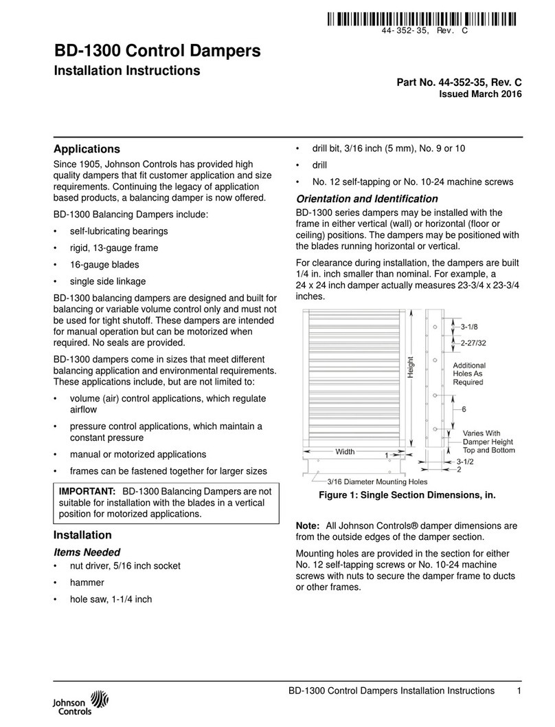
Johnson Controls BD-1300 User manual

Johnson Controls
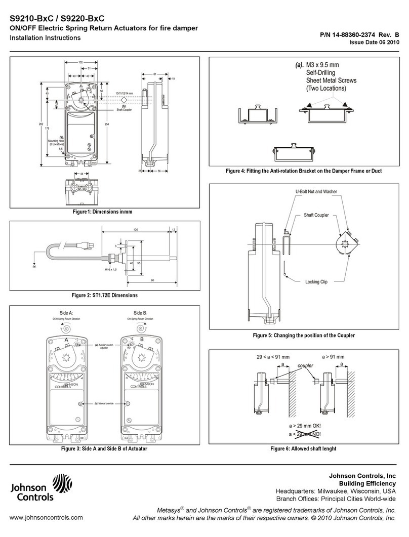
Johnson Controls S9210-BC Series User manual

Johnson Controls
Johnson Controls YORK ACTIVA 100 User manual

Johnson Controls
Johnson Controls FS-1300 User manual
Johnson Controls
Johnson Controls RF-2000 User manual

Johnson Controls
Johnson Controls FD-1600 User manual
Popular Fire And Smoke Damper manuals by other brands

Greenheck
Greenheck CRD-300WT Installation, operation and maintenance manual

SMAY
SMAY KWP-L installation manual

Priorit
Priorit PRIODOOR ETX-RDA Assembly and operating manual

Greenheck
Greenheck ESK-402 Installation, operation and maintenance

NCA
NCA FSD-RD-211 Installation, operation & maintenance instructions

EKOVENT
EKOVENT EKO-RBG1 Installation and maintenance instructions