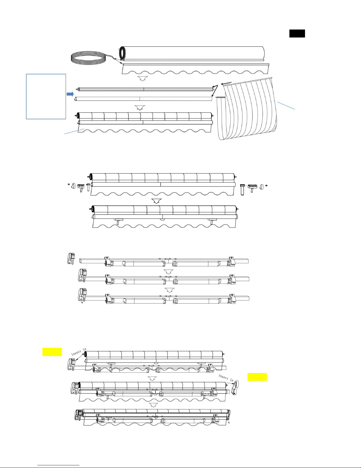
Aleko Victoria Series User guide

ALEKO®Victoria Series Retractable Awning
Instructions for Installation and Operation
PLEASE DO NOT RETURN THIS PRODUCT TO THE STORE!
The owner’s manual includes assembly and operating instructions, safety warnings, and the lists of parts and
hardware. If you have questions about the assembly or operation of this product, or have missing or defective
parts, please e-mail us at Sales@AlekoProducts.com or call us (M-F 7:00 AM to 5:00 PM PST) at 253-872-3656
Contents
Parts Diagram - - - - - - - - - - - - - - - 1
Steps of Assembly - - - - - - - - - - - - - 2 / 3/ 4/ 5
Specifications - - - - - - - - - - - - - - - 5
Safety Installation and Operation - - - - - - - - - - 6
Part List - - - - - - - - - - - - - - - - - 6
Installation Procedure - - - - - - - - - - - - 7 / 8 / 9
Common Mistakes - - - - - - - - - - - - - - 9
Motor Installation(Optional) - - - - - - - - - - - 9/ 10
www.AlekoProducts.com

Parts Diagram
A-1.Roller(left)
A-2.Roller(right)
A-3.Roller connector
A-A-1.Bolt M4 x 15
B-1.Torsion bar(left)
B-2.Torsion bar(right)
B-3.Torsion bar connector
B-B-1.Bolt M6 x 45
B-B-2.Bolt M6 + Washer Ø6
C-1.Front bar(left)
C-2.Front bar(right)
C-3.Front bar link tube
D-1.Left roller support
D-2.Bolt M10 x 60
D-3.Gear box
D-4.Bolt M6 x 50
E-1.Right roller support
E-2.Round shaft cover
F-1.Square shaft
F-2.Round shaft
G .Bolt M10 x 65
H. Arm shoulder
I. Adjustable bolt M10 x 30
J. Washer Ø10
K. Bolt M10 x 50
L-1.Left arm
L-2.Right arm
M .Fabric
N. Fabric liner
O .Valance
P. Blocker
Q-1.Arm-bar Link
Q-2.Bolt M8 x 12
Q-3.Self lock nut M10 + Washer
Ø10
R. Plastic cover for front bar
S. Bolt for Cover & Fabric Liner
T. Hand Crank
U. Cover for Torsion Bar
D-1
D-3
D-4
F-1
A-1
A-A-1
A-2
T
M
L-1
L-2
O
C-2
C-1
C-3
B-2
B-1
B-B-2
B-B-1
A-3
F-2
E-2
E-1
Q-1
B-3
N
R
S
K
D-2
G
H
I
J
Page 1
J
Q-2
Q-3
P
A-A-1
U

WARNING:
FAILURE TO FOLLOW THESE INSTRUCTIONS
COULD RESULT IN PERSONAL INJURY!
Steps of Assembly
1. Roller Assembly: Insert roller connector (A-3) into right roller (A-2), fasten it with bolt
(A-A-1). Link the left roller (A-1) to the connector (A-3), fasten it with bolt (A-A-1). Now you
have a full length roller.
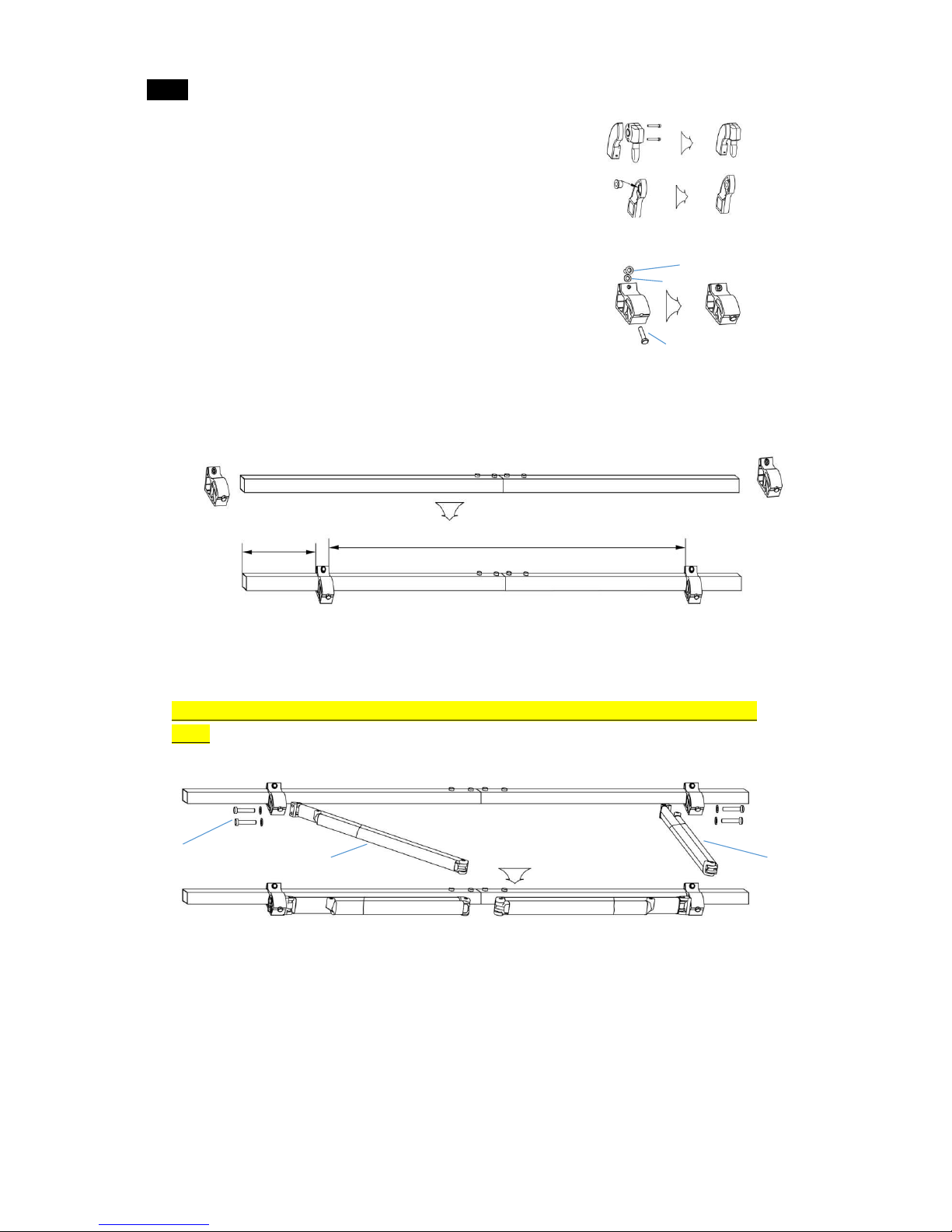
2. Front bar assembly: Insert front bar connector (C-3) into right front bar (C-2), fasten with
bolt (A-A-1). Link left front bar (C-1) with the connector (C-3), fasten it with bolt (A-A-1).
Now you have a full length front bar.
3. Torsion bar assembly: Insert torsion bar connector (B-3) into right torsion bar (B-2),
fasten with bolt (B-B-1 & B-B-2). Link left torsion bar (B-1) with connector (B-3), fasten
with bolt (B-B-1 & B-B-2). Now you have a full length torsion bar.
A-1
A-3
A-2
A-A-1
C-1
C-3
C-2
A-A-1
B-1
B-2
B-3
B-B-2
B-B-1
Page 2

4. Installation of gear box: Combine left roller support (D-1)
with gear box (D-3) through bolt (D-4) M6x50, refer to
Diagram 1. Then install right roller support (E-1) and round
shaft cover (E-2) together as in Diagram 2.
5. Installing of arm shoulder: Assemble arm shoulder (H), bolt
M10x65 (G), washer and adjustable bolt M10x30 (I) together,
refer to Diagram 3.
6. Torsion bar and arm shoulder assembly: Link torsion bar and arm shoulder, tighten arm
shoulder with bolt M10x65 (G) with socket head wrench. Set positions of arm shoulder for
both side against different awning sizes. (This step is already done by factory.)
7. Arm shoulder Assembly: Link both left (L-1) and right (L-2) arms with corresponding
arm shoulder through bolt M10x50 (K). (This step is already done by factory.)
Warning: Arms should be tied together during installation to avoid bouncing out and cause
injury.
8. Spread out both of the fabrics (M) and valance (O) and insert fabric liner (N). Push one
end of fabric with liner inserted into gauges on roller, then the other end through front bar.
(Attention:The fabric has two sides: front and back. The back side is with hem facing
downwards) See below image.
D-1 D-3 D-4
Diagram 1
Diagram 2
E-2 E-1
Diagram 3
H
I
L-1
L-2
K
Page 3
G

9. Front bar wrist support assembly: Blocker (P) and Arm-Bar Link (Q-1) into big trough of
front bar, put both left and right plastic cover (R) to each end of the bar, then fix the Bolt for
Cover & Fabric Liner (S) to the plastic cover(R).
10. Left roller support with gear box assembly: Hammer left roller support with gear box
into torsion bar with gentle strength. Tighten screws with screwdriver.
11. Assembly of whole awning: Insert square shaft (F-1) in roller with fabric into square
hole of gear box, then knock round shaft cover (E-2) into right roller support (E-1) and link
it with round shaft of right side using hammer, tighten screw on it using screwdriver.
A
C
M
O
Page 4
P
Q-1
R
S
Through from
Through the
fabric into
roller and front
bar
Insert in
Insert in

12. Setting position of whole awning: Make sure two arms are tied tightly to torsion bar,
move front bar wrist support (Q-1) until it connects with arms’ hole. Align the front bar and
roller, tighten bolt (Q-2) of two Arm-Bar Link upwardly by screwdriver. Then fasten self
locking nut M10 +Washer Ø10(Q-3) with bolts up to 95% tight using ribbon tube spanner.
Lastly, Blocker (P) in centre of two arm, fasten it when awning is opened.
13. FAQ: What if the fabric wraps unevenly or the two arms cannot open together at the
same time?
Answer: Look at the stability of two arms and adjust the front bar wrist of the faster arm
outwards accordingly.
Specification
Product name
Material and surface
treatment
Applicable wall
type
Recommended
installation
height
Applicable weather
Retractable
awning
(Please see
details on the
package)
Materials: Steel tube,
Aluminum alloy, plastic
parts, polyester fabric.
Service treatment :
tubes: spray paint and
oxidation
Cloth surface: PU, UV,
waterproof
Reinforced
concrete walls,
brick walls, and
wooden walls
8 ft ~ 12 ft
The products are
used to shield
sunshine. Applicable
when wind is under
level 5. Not suitable
for rainy weather.
The lifespan of the product is 5 years (assuming the frame is opened and closed twice a
day).
Only screws for reinforced concrete walls and brick walls are provided. If you want to
install the product on a wooden wall, please seek advice from professional installer.
Important: Read “Instructions for installation and operation” carefully before installation. Keep the
instruction in a safe place for future reference.
Page 5
Insert in
Tight
Tight

Safe installation and operation
Never install it in high and windy places, as the sunshade may drop and hurt
someone
Don’t use it in places that have vibrations or impulsions.
Don’t use it in places of high temperature such as walls near furnaces.
Don’t put heavy things on the frame as it may fall down and cause damages.
Please close the sunshade in windy and rainy days.
Never use it for other purposes other than suggested
Be careful with your fingers during installation.
Two adults are needed to move and install the sunshade as the product is big and
heavy.
Please use all the screws and nuts correctly during installation as it is very dangerous
if you leave it loose.
Parts List
Please prepare the following tools before installation (not included with the product)
Product model
No. Of wall
brackets
No. Of expansion
bolts
< 10.8ft
2
4
10.8ft ~ 14ft
3
6
14.5ft ~20ft
4
8
Awning
Hand Crank
Instructions
Wall Bracket
Page 6
Power drill
Expansion bolts
Tape
Wrench

Installation Procedure
1. Measure the distance along the wall where it can be placed. Drill holes for wall
brackets on the wall according to the installation distances and height of the wall brackets.
The diameter and depth of hole must be the same as expansion bolts.
The holes of each group must be on
the same line in transversal
direction and vertical direction.
(Note: It is recommended to draw
lines on the wall first to ensure
precise position and size of the
holes)
2. Hammer all the expansion bolts into the holes. Then
take down the nuts and washer.
(Note):
The expansion bolts must be hammered into the wall
completely.
The bolts must be stick out of the wall so that the wall brackets
can be installed on it.
The nut and washer might be separated from the bolt during
process of transportation, please put them back into their original
positions before hammer them into the wall.)
3. Take down the original bolts of the wall
brackets as shown in the figure, use
expansion bolts to fix the wall brackets on
the wall. Do not tighten completely, leave
wall brackets to stay on the wall with little
movement.
Page 7
3.5 Inch
Ground
*** Make sure all the all bases are on the same
horizontal line.

Installation distance between wall brackets
Awning < 10.8ft
Only 2 wall brackets for each end of torsion bars
Awning 10.8ft ~ 14ft
2 wall brackets at each end of torsion bar, a middle bracket in
between distance of 2 arm shoulders (arm brackets refer to
steps of assembly 6)
Awning 14.5ft ~ 20ft
2 wall brackets at each end of torsion bar, 2 middle brackets
divide into equal length in between distance of 2 arm shoulders
at each end of torsion bars. (steps of assembly 6)
4. As shown in the figure, we recommend making the
awning surface to form an angle of about 80 degrees
with the wall when it is open.
A) The height of front bar you desire
L) The length of the arm stretch out
C) The height of wall brackets
You can follow this formula: C= A + 0.17*L
5. Install the awning on the wall brackets according to “Installation distances between
wall brackets” above, put the original bolts on the wall brackets and tighten them. Finally
fasten all expansion bolts.
6. ALTERNATIVELY, TWO WAYS CEILING/WALL BRACKETS
are available and sold separately on www.AlekoProducts.com web
site.
Measure distance and drill holes on the soffit. Hammer expansion
bolts into holes (Refer to step 2-3). Lastly, Fit awning into square
space as label.
Page 8
Torsion bar
Side View

CAUTION: PROPER LOCATION OF THE BRACKETS IS THE MOST IMPORTANT ASPECT OF THE
AWNING INSTALLATION. IT IS CRITICAL THAT YOU FASTEN ALL THE MOUNTING BRACKETS
TO STUDS, JOISTS, HEADERS OR OTHER MAJOR STRUCTURAL COMPONENTS.
WARNING: FAILURE TO SECURELY FASTEN ALL THE BRACKETS TO THE WALL COULD
RESULT IN THE COLLAPSE OF THE AWNING AND CAUSE PERSONAL INJURY OR DEATH.
7. Instruction for front side leveling
1Loosen the locking nuts.
2Turn the jack bolt to adjust pitch
3Adjust the arm until the front side stays in
horizontal line.
4Tighten the locking nuts.
Common Mistakes
Motor Installation(optional)
Motor installation Motor wiring diagram
Page 9
Diagram 4
Motor
Correct operation
Wrong operation
Warning: When the front bar touches the
roller as shown in the figure, don’t try to
make them closer, otherwise the product
might be damaged.
JACK BOLT
ARM
LOCKING NUTS
Front bar
Fabric
fabric
Black
Brown
Yellow/Green
Blue
M
Switch
N
L
PE

Installation of motor bracket: Combine left roller support with motor bracket through bolt
M6 x 50, see Diagram 4 above;
Fixing guide:
1. Please connect the down-lead of the motor and the wire of power supply to the switch
according to the diagram. (Make sure to turn off the power supply first.)
2. The stroke of the motor was placed at the maximum after production.
3. You should turn off the power supply before using the hand crank.
Adjustment:
The motor has two regulation holes, using the screw driver you can adjust the opening
distance of the awning.
-1. Indicating the increase or decrease of the opening of the awning: “+” stands for
increase, “-” for decrease.
-2. Opening direction may be different when the motor is installed, if it is attached
inversely or on the other side. Please check the motor opening direction during
adjustments.
-3. Note: The awning operation is already set during production. If adjusting is needed,
please contact a local dealer or a professional installer.
Attention:
1. The hand crank will not work when the power is turned on. (Important)
2. The awnings driven by the tubular motor have the built-in thermal protection device,
which can keep working for 2 minutes and then stop. After 10 minutes, it will continue to
operate.
3. The built-in tubular motor of awning is suitable for working from -15℃+ 40℃.
4. Do not hang or place any items on any part of the awning.
5. If the motor doesn’t work, or the remote control distance is getting short, you should
check the built-in parts of the remote and the batteries.
6. Please check the fixed bracket regularly to make sure they have not come loose,
especially in windy/rough weather areas.
7. The awning should be fully closed in windy conditions.
Page 10

For more information, parts and accessories
Please visit our web site:
www.AlekoProducts.com
PLEASE DO NOT RETURN THIS PRODUCT TO THE
STORE!
If you have questions about the assembly or operation of this product
Or have missing or defective parts, please e-mail us at
Sales@AlekoProducts.com
Or call us (M-F 7:00 AM to 5:00 PM PST) at 253-872-3656
Other manuals for Victoria Series
3
Table of contents
Other Aleko Accessories manuals
Popular Accessories manuals by other brands

ROSE DISPLAYS
ROSE DISPLAYS SUPERSNAP WITH CABLE CLIP AND BALL CHAIN instruction sheet

Autel
Autel MaxiTPMS TS508 manual

Johnson Controls
Johnson Controls LN Series installation instructions

Waterpik
Waterpik Waterflosser WP-150 Series manual

EMX
EMX NIR-50 operating instructions

B.E.G. LUXOMAT
B.E.G. LUXOMAT PD4-M-DIM-HVAC Installation and operating instruction