Aleo ELEGANTE User manual

1
Please read this carefully
prior to installation.
Store in a safe place for
maintenance.
BIPV modules
ELEGANTE
INSTALLATION
MANUAL 1.5
07/2022

aleo solar GmbH | Marius-Eriksen-Straße 1 | 17291 Prenzlau | Germany | info@aleo-solar.com
Installation Manual GG Elegante Rel. 1.5, 01/2022, EN
Copyright © 2021 aleo solar GmbH
2
2 Product support
In addition to this installation Manual, aleo solar also pro-
vides further information on its website.
www.aleo-solar.de
Contact
aleo solar GmbH
Marius-Eriksen-Straße 1
17291 Prenzlau
Germany
Tel. +49 (0)3984 8328-0
Fax +49 (0)3984 8328-115
E-Mail info@aleo-solar.com
Web www.aleo-solar.com
© 2022 aleo solar GmbH
This installation Manual is protected by copyright. All rights
reserved. Copying, reproduction, translation, or conversion
to any type of electronic media or machine readable form,
in its entirety or parts, is not permitted. An exception will be
made for a backup copy for your own use. aleo solar reserves
the right to change this document withhout prior notice.
aleo® and aleo solar® are registered, protected trademarks
of aleo solar GmbH.
Deutsch
(de-DE)
Wenn Sie diese Insatallationsanlei-
tung in deutscher Sprache benöti-
gen, wenden Sie sich bitte an aleo
solar, siehe Kap. 2.
English
(en-GB)
If you require this installation ma-
nual in English, please contact aleo
solar, see chap. 2.
1 Table of content
2 Product support ......................2
3 Explanation of
safety guidelines ......................3
4 About this manual ....................3
4.1 Detailed information for
installers and planners ..............3
5 About aleo modules ...................3
5.1 Intended use........................3
5.2 Product-specific information ........3
6 Installation ...........................4
7 Mounting specifications ...............7
7.1 Safety glass regulations.............7
7.2 Linearly supported modules .........7
7.3 Punctually supported modules.......7
8 Electrical installation ..................8
8.1 Personal protection .................8
8.2 Electrical Connections ..............8
8.3 Junction box .......................9
8.4 Cable couplers for junction boxes ....9
8.5 Connectors .........................9
8.6 Cables .............................9
8.7 Laying the string cables .............9
9 Maintenance.........................10
9.1 Review ............................10
9.2 Inspections ........................10
9.3 Cleaning. . . . . . . . . . . . . . . . . . . . . . . . . . . .11
9.4 Repairs .............................11
10 Decommissioning ....................12
10.1 Disposal...........................12
10.2 PV CYCLE ........................12

aleo solar GmbH | Marius-Eriksen-Straße 1 | 17291 Prenzlau | Germany | info@aleo-solar.com
Installation Manual GG Elegante Rel. 1.5, 01/2022, EN
Copyright © 2021 aleo solar GmbH
3
3 Explanation of
safety guidelines
The information on warning and cautions is structured
as follows
The WARNING symbol indicates an imminently or
potentially dangerous situation which can lead to
serious injuries if not avoided.
NOTE indicates a potentially dangerous situation
which can cause material damage if not avoided.
If this symbol also appears on a danger or warning
product label, it is warning you of the danger caused
by electric current or voltage which can lead to perso-
nal injury if you fail to observe the instructions.
4 About this manual
This Edition 1.5 installation manual GG Elegante is
released with the edition date 07/2022. Installation
manuals related to other aleo products (framed mo-
dules) do not lose their validity. aleo solar constantly
strives to improve its products and their documenta-
tion. Therefore, we advise you to use the latest version
of the manual at all times.
Hand over this installation manual to the operator
after installation and ensure you have confirmation
of receipt.
4.1 Detailed information for
installers and planners
4.1.1 Information on the aleo solar website
You can find the latest release of the installation ma-
nual and additional information on aleo solar’s website
www.aleo-solar.com
4.1.2 Information sources for operators
If you have any queries about the latest release, con-
tact your aleo solar specialist partner or aleo solar
directly (see ch. 2 „Contact“).
5 About aleo modules
5.1 Intended use
aleo modules are suitable for installations near lives-
tock farms and coastal regions.
Observe all the applicable legislation, regulations,
guidelines and standards when installing the modules.
Do not install aleo modules on vehicles and do not use
them in air, space or seafaring applications.
Do not use aleo modules if they are exposed to con-
centrated sunlight or strong artificial light, or if they
could be immersed in water or other liquids or exposed
to vapour.
5.2 Product-specific information
Product-specific information (e.g. the data sheet)
contains details of a particular type of module.
This module is rated for use in application class A ac-
cording to IEC 61730. For electrical ratings please refer
to the data sheet. Data sheets may change without
prior notice. If the information in the data sheet differs
from this manual, the data sheet takes precedence.
Under normal conditions, solar modules are likely
to experience conditions that produce more current
and/or voltage than reported at standard test con-
ditions.
Accordingly, the values of ISC and VOC marked on
the modules should be multiplied by a faktor of 1.25
when determining component voltage ratings, con-
ductor ampacities, fuse sizes, and size of controls
connected to the PV output.

aleo solar GmbH | Marius-Eriksen-Straße 1 | 17291 Prenzlau | Germany | info@aleo-solar.com
Installation Manual GG Elegante Rel. 1.5, 01/2022, EN
Copyright © 2021 aleo solar GmbH
4
6 Installation
Check the packaging for damage.
Follow the packaging instructions.
If the packaging is damaged,
contact the shipping company.
Do not stack packaging units.
Side pads serve as packaging stability
Before unwrapping the module remove the
side pads at the top
Leave the modules in the original
packaging until installation.
Store the modules safe in dry rooms.
The packaging is not weatherproof!
Store the modules at an ambient
temperature of max. 40°C
NOTE ! Damage to the modules!
Open the packaging as shown in the picture
Two persons are required to lift the modules!
NOTE ! Damage to the modules!
Do not stack the modules.
Leave the modules in the packaging
before mounting

aleo solar GmbH | Marius-Eriksen-Straße 1 | 17291 Prenzlau | Germany | info@aleo-solar.com
Installation Manual GG Elegante Rel. 1.5, 01/2022, EN
Copyright © 2021 aleo solar GmbH
5
WARNING ! Danger due to electric shock!
Block off the danger zone for people or
animals before beginning the installation.
Always carry the aleo modules
with one other person.
WARNING ! Danger due to electric shock!
Only use components which are in perfect
condition. Do not install solar modules
with visible damages.
NOTE ! Damage to the modules!
store modules in an upright position on
wedges with suitable padding. Use adequate
padding also between individual modules.
NOTE ! Damage to the modules!
Use glass suction cups to transport the
modules.
Hold modules on their long sides.
NOTE ! Damage to the modules!
When transporting modules make sure not
to put any strain or pressure on the junction
box and cables.

aleo solar GmbH | Marius-Eriksen-Straße 1 | 17291 Prenzlau | Germany | info@aleo-solar.com
Installation Manual GG Elegante Rel. 1.5, 01/2022, EN
Copyright © 2021 aleo solar GmbH
6
Protect yourself from burning by wearing
gloves and suitable clothing.
Only use approved, insulated tools for
installation or maintenance work on live
parts.
NOTE ! Damage to the modules!
Changes may be made to the module only
in case they have been approved by aleo in
writing.
Work in dry conditions. NOTE ! Damage to the modules!
Risk of modules falling or colliding
with other objects!
NOTE ! Damage to the modules!
Never step on the modules!
Do not apply mechanical stress to the
modules.
Do not drop any objects on the modules.
Beware of sharp glass edges or flying glass
splinters, be especially careful with glass
edges.

aleo solar GmbH | Marius-Eriksen-Straße 1 | 17291 Prenzlau | Germany | info@aleo-solar.com
Installation Manual GG Elegante Rel. 1.5, 01/2022, EN
Copyright © 2021 aleo solar GmbH
7
7 Mounting specifications
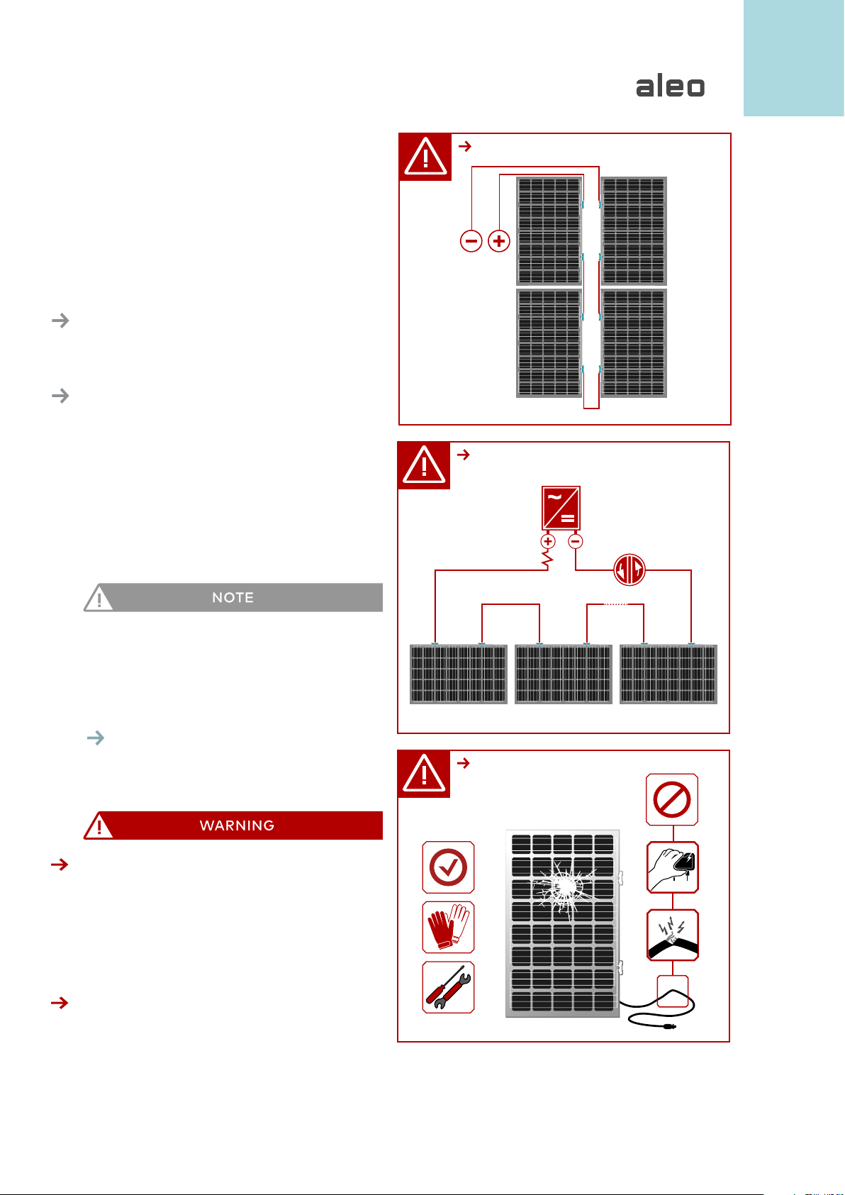
Always ensure that the mounting structure is earthed
(R ≤ 10).
Leave a minimum distance of 5mm between modules
when mounting. This prevents mechanical tension
due to thermal expansion of the glass.
Leave a distance of at least 4cm between the back
side of the modules and the underlying surface, to
ensure the rear ventilation of the module.
7.1 Safety glass regulations
The product Elegante is a photovoltaic composite
safety glass (PV-VSG), marked with the code Z-70.3-
258 for the general architectural license (in Germany
“allgemeine bauaufsichtliche Zulassung - abZ”). The
module is a laminated safety glass (VSG) and should
therefore be used as a construction product.
In case of uncertainty regarding the mounting and
for each topic not contained in this manual, please
contact us.
7.2 Linearly supported modules
Most of the architectural applications foreseen for this
product, e.g. carports or verandas, take reference to
mounting types in which the modules are supported
on at least two opposite sides through a continuous
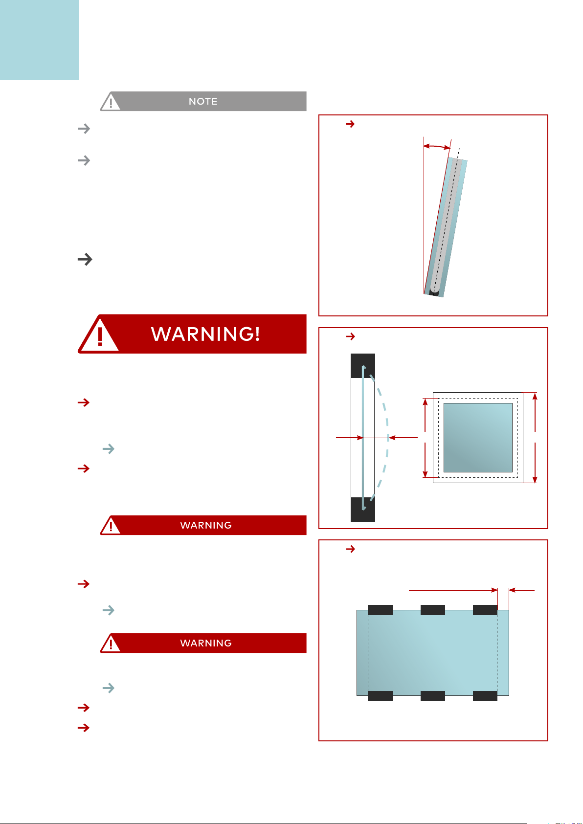
line. Depending on their inclination against the per-
pendicular, they are divided into overhead glazing
(inclination > 10°) or vertical glazing (inclination ≤10°)
.Figure 7A
Elegante Modules are licensed for both kinds of in-
stallation.
Mounting depth:
In case of an all-round linear support (e.g. in a frame)
the mounting depth must be at least 10mm. In the
case of two or three-sided linear support, the moun-
ting depth must be at least 15mm.
Deflection:
The assembly must be carried out in such a way that
the deflection of the module is not more than 1/100.
Figure 7B
Since the wind can equally act as a pressure or soak
load, the linear support must ensure that the glass
safely remains in the support for both types of load.
No contact between glass and hard materials (e.g.
metal, wood) may occur under load and temperature
effects.
For distance between supports higher than 1.20 m
there is an increased risk that the glass will leave the
bearing in the event of a break.
Therefore, modules with a linear support along the
short side of the Elegante module, where the span
is higher than 1.20m, must be placed on all sides in a
linear support.
Drilling and cut-outs in the modules are not permitted.
The free edge of the module, parallel and perpendicu-
lar to the bearing, can be at most 30% of the support
length, but in any case not more than 300mm.
Overhead glazing:
In case of overhead glazing we recommend that the
surface of the modules is inclined at an angle of at
least 5°, so that precipitation can drain off supporting
the modules self-cleaning.
Elegante Modules linearly supported on the long sides,
can bear pressure loads till 7500 Pa and soak loads
till 5400 Pa, according to IEC 61215 (Crystalline silicon
terrestrial photovoltaic (PV) modules – Design qua-
lification and type approval), without compromising
the functional capabilty of the PV module.
7.3 Punctually supported modules
The technical rules for the dimensioning and execution
of point-mounted fastening types apply:
The point holders must be made of stainless steel with
at least a corrosion resistance class II.
The assembly must be designed in such a way that
the modules can be installed with consideration of
structural tolerances and that the glass cannot come
in contact with other hard components (e.g. metal)
under operating conditions (load, temperature, inflec-
tion of load bearing construction).
The free edge of the glass must not be more than
300 mm and at least 80mm.
Figure 7C

aleo solar GmbH | Marius-Eriksen-Straße 1 | 17291 Prenzlau | Germany | info@aleo-solar.com
Installation Manual GG Elegante Rel. 1.5, 01/2022, EN
Copyright © 2021 aleo solar GmbH
8
The required minimum mounting depth of a clamp
is 15mm.
Elegante Modules punctually supported with clamps
on the long sides, mounted according to the rules, can
bear pressure and soak loads till 5400Pa, according to
IEC 61215 (Crystalline silicon terrestrial photovoltaic
(PV) modules – Design qualification and type appro-
val), without compromise the functional capabilty of
the PV module.
8 Electrical installation
8.1 Personal protection
High DC voltages during storage, installation, ope-
ration and maintenance. Risk of fatal electric shock!
aleo modules may only be installed by qualified
technicians with a high level of expertise (see sample
of cennection
Figure 8A ).
Never touch the electrical connections of a solar mo-
dule under any circumstances, not even if you have
disconnected the photovoltaic generator.
Electric arcs are generated when electrical compo-
nents are connected or disconnected incorrectly.
Before you carry out any work on electrical compo-
nents, disconnect the photovoltaic generator.
Figure 8B
Contact with live parts due to defective insulation or
damaged / fallen off junction box covers.
Figure 8C
Do not touch damaged parts with your bare hands.
Use protective clothing and suitable, insulated tools.
10°
≥ 80mm & ≤ 300mm
7A
7C
fG ≤ lG /100
max. 15mm
lGlW
7B

aleo solar GmbH | Marius-Eriksen-Straße 1 | 17291 Prenzlau | Germany | info@aleo-solar.com
Installation Manual GG Elegante Rel. 1.5, 01/2022, EN
Copyright © 2021 aleo solar GmbH
9
8.2 Electrical Connections
For modules connected in series, only modules of the
same amperage rating may be used together. For
modules connected in parallel, modules with the same
voltage ranges must be used together. The modules
must not be operated at a higher voltage than the
permissible system voltage.
8.3 Junction box
Avoid standing water in the junction box area.
When mounting horizantally, make sure that the
junction boxes are facing upwards.
The junction boxes and the surrounding area (at least
15 mm from the glass edge inwards and at least 25
mm to the left and right of the junction box) must
be protected against direct sunlight, precipitation
and dirt.
The use of an aluminum clamping rail is recommended
for this purpose.
8.4 Cable couplers for junction boxes
Only use cable couplers that are the same type and
compatible to the specific junction box.
Insert the cable couplers in the junction boxes only
through the outer slots on the left and on the right
of the module, as shown in the picture.
Figure 8D
8.5 Connectors
Incompatible or unsuitable connectors can overheat.
Fire hazard!
Only use connectors that are the same type and
compatible to the specific inverter.
This module type can be fitted with the following
connectors:
TE - SOLARLOK Slim Line (Plus:1-1987559-1; Minus:
1-1987559-2)
You can remove the connector on a module and repla-
ce it with another connector, if necessary. You retain
D
C
S
W
I
T
C
H
8B
8C
8A

aleo solar GmbH | Marius-Eriksen-Straße 1 | 17291 Prenzlau | Germany | info@aleo-solar.com
Installation Manual GG Elegante Rel. 1.5, 01/2022, EN
Copyright © 2021 aleo solar GmbH
10
8D
8E
the manufacturing warranty if you remove and mount
with approved tools in the proper way and according
to the connector manufacturer‘s instructions.
8.6 Cables
Only solar cables with an 4mmcross-section and
appropriate connectors may be used for connecting
the modules.
8.7 Laying the string cables
Pay attention to bend the cables after they exit from
the connector, in order to keep them waterproof at
the cable outlet.
Figure 8E
This keeps the cables waterproof at the cable outlet.
Protect cables from direct sunlight, precipitation
and dirt.
Figure 8F
Cables from module strings are laid as near to each
other as possible to minimise the effects of being
struck by lightning.
9 Maintenance
Inspect and maintain your system to:
• keep it safe and reliable
• achieve top output
• prevent damages
• protect your investment
9.1 Review
aleo solar recommends carrying out a thorough review
at least every 4 years. This includes the following work
in addition to the inspection:
RECOMMENDATION
aleo solar explicitly recommends annual inspections
and a more thorough inspection and measurement
every 4 years.
We also recommend the use of a monitoring system
to identify any outages or problems quickly. Inspecting
the output of your photovoltaic system regularly can
help to discover problems promptly, and ensures your
photovoltaic system operates at top performance,
preventing loss of output.
cable coupler
plus
cable coupler
minus
blind plug
8F

aleo solar GmbH | Marius-Eriksen-Straße 1 | 17291 Prenzlau | Germany | info@aleo-solar.com
Installation Manual GG Elegante Rel. 1.5, 01/2022, EN
Copyright © 2021 aleo solar GmbH
11
For the proper maintenance and repair of your aleo
solar photovoltaic system, contact your aleo solar
dealer or get in touch with aleo solar directly (see Ch.
2.2: „Contact“).
9.2 Inspections
aleo solar recommends an inspection every year.The
inspection includes the following aspects.
9.2.1 Inspecting the generator
• strings: condition of the insulation and mounting
• condition of the junction box
• condition of the visible connectors
• condition of the mounting system
• dirt on modules: type and degree of dirt
• shade circumstances (e.g. from trees or neigh-
bouring houses)
9.3 Cleaning
Depending on the ambient conditions, modules are
likely to get soiled more or less heavily over time. This
can cause reduced output.
Dirt could be:
• dust, pollen or seed
• leaves or twigs
• deposits from stable vapour
• moss, algae, fungi or bacteria growing on
• depo sits (in short: biofilms)
• salt (in coastal regions)
9.3.1 Safety precautions
Contact of live parts with water.
Risk of electric shock!
Never use a high pressure cleaner.
You will also retain the manufacturer‘s warranty as a
result of this measure.
9.3.2 Glass surfaces
The glass surfaces of aleo modules have microscopic
structures or anti-reflex coatings. Ensure that these
do not get damaged. Do not use any cleaning agents
which will polish or scratch the surface.
Avoid the use of very hard water.
Also avoid the use of distilled or demineralized water
if possible.
Avoid the use of acids, bases or other aggressive
cleaning agents.
Dirt- or water-repellent coatings subsequently applied
to the modules can negatively affect the efficiency of
the aleo modules and therefore the power output of
the whole photovoltaic system. We therefore advise
against the use of these agents.
RECOMMENDATION
For cleaning the glass module surfaces,
aleo solar recommends:
• rainwater without additives with its temperature
matching the temperature of the module
• a soft sponge or a soft brush
• If necessary, use a telescopic rod with a sponge or
soft brush attached on the end. The rod can have
a water pipe integrated.
For stubborn patches of dirt, use the following to help:
Isopropanol: aleo solar recommends a mixture of
isopropanol and rainwater to the ratio of 1:1
Glass cleaner: As an alternative, aleo solar recom-
mends clear, colourless glass cleaner with no ethanol
or denaturants (e.g. Bitrex®).
Anti-reflex glass
aleo modules have an anti-reflex layer on the glass
surface to achieve a higher output. This means that
some marks (e.g. fingerprints) are more visible than
on normal glass. These marks are mostly seen as
shimmering patches.
These kinds of marks do not have any

aleo solar GmbH | Marius-Eriksen-Straße 1 | 17291 Prenzlau | Germany | info@aleo-solar.com
Installation Manual GG Elegante Rel. 1.5, 01/2022, EN
Copyright © 2021 aleo solar GmbH
12
measurable effect on the module output and fade
away after about 2 weeks of being exposed to we-
ather conditions, as sunlight and rain break them
down.
9.3.3 More frequent cleaning
RECOMMENDATION
In environments subject to heavy soiling, we recom-
mend making the intervals for inspections and clea-
ning shorter than just once a year.
aleo solar recommends contracting a specialised
company to clean your photovoltaic generator pro-
perly without treading on the modules, if frequent
cleaning is necessary.
9.4 Repairs
9.4.1 Modules
A defective module can cause loss of output, as well
as consequential damage. If an aleo module needs
repairing, first get in touch with aleo solar (see Ch. 2:
„Contact“).
Never, under any circumstances, repair an aleo module
yourself: only contract technicians who have been
authorized by aleo solar to avoid loss of warranty.
Before you carry out any maintenance work on aleo
modules, deactivate the module string or the whole
generator if necessary. Observe the warnings and
notes in Ch. 6.2.2.
9.4.2 System parts
For repairing other system parts (e.g. substructure,
connection boxes), contract authorized technicians to
do the work or contact aleo solar directly
(see Ch. 2: „Contact“).
10 Decommissioning
10.1 Disposal
Dispose of the aleo modules at the end of their service
life contacting a disposal company.
Never dispose of aleo modules with household waste.
10.2 PV CYCLE
aleo solar is member of PV CYCLE. Used or damaged
PV modules from aleo solar are disposed of by PV CY-
CLE without any costs. Under certain circumstances
transport costs may apply in the context of disposal.
PV CYCLE offers a comprehensive collection network
for PV module waste, from fixed collection points to
on-site pick-up.
Please contact operations@pvcycle.org for your indi-
vidual disposal solution.

aleo solar GmbH | Marius-Eriksen-Straße 1 | 17291 Prenzlau | Germany | info@aleo-solar.com
Installation Manual GG Elegante Rel. 1.5, 01/2022, EN
Copyright © 2021 aleo solar GmbH
13

aleo solar GmbH | Marius-Eriksen-Straße 1 | 17291 Prenzlau | Germany | info@aleo-solar.com
Installation Manual GG Elegante Rel. 1.5, 01/2022, EN
Copyright © 2021 aleo solar GmbH
14
Notes

aleo solar GmbH | Marius-Eriksen-Straße 1 | 17291 Prenzlau | Germany | info@aleo-solar.com
Installation Manual GG Elegante Rel. 1.5, 01/2022, EN
Copyright © 2021 aleo solar GmbH
15

www.aleo-solar.com
Other manuals for ELEGANTE
1
Table of contents
Other Aleo Solar Panel manuals
Popular Solar Panel manuals by other brands

GOAL ZERO
GOAL ZERO Boulder 50 user manual

CanadianSolar
CanadianSolar CS6A-P installation manual

Qcells
Qcells Q.PEAK DUO XL-G9.2 Series Installation and operation manual

Qcells
Qcells Q.PEAK DUO XL-G10.2 Installation and operation manual

Qcells
Qcells Q.PEAK DUO L-G8 Series Installation and operation manual

CanadianSolar
CanadianSolar CSFDC-20-1218A1 user manual

Qcells
Qcells Q.PEAK DUO ML-G11 Series Installation and operation manual

SR PORTABLES
SR PORTABLES MC4 instruction manual

patura
patura 148721 user manual

Riello
Riello CSV 25 R installation instructions

Kyocera
Kyocera KD Series Assembly and maintenance instructions

Solar Fabrik
Solar Fabrik M Series Mounting instructions