aleo solar GmbH | Marius-Eriksen-Straße 1 | 17291 Prenzlau | Germany | info@aleo-solar.com
Quick Reference Manual Rel. 4.2, 08/2015, en-GB-DE (1)
Page 10/19
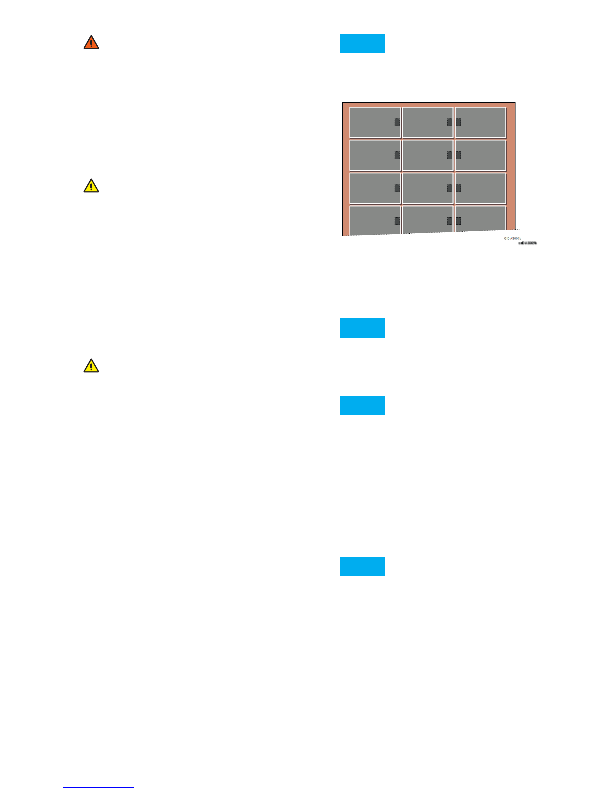
10.2 Clamp mounting for modules with standard
frames
10.2.1 Arranging the clamps
■ Permissible arrangement
Fig.5 55 Permissible clamp arrangement for framed
modules
a: Symmetrical clamping on the long sides,
b: Asymmetrical clamping on the long sides
(acceptable for certain load levels),
c: Symmetrical clamping on the short sides.
d: Clamping on both short and long sides.
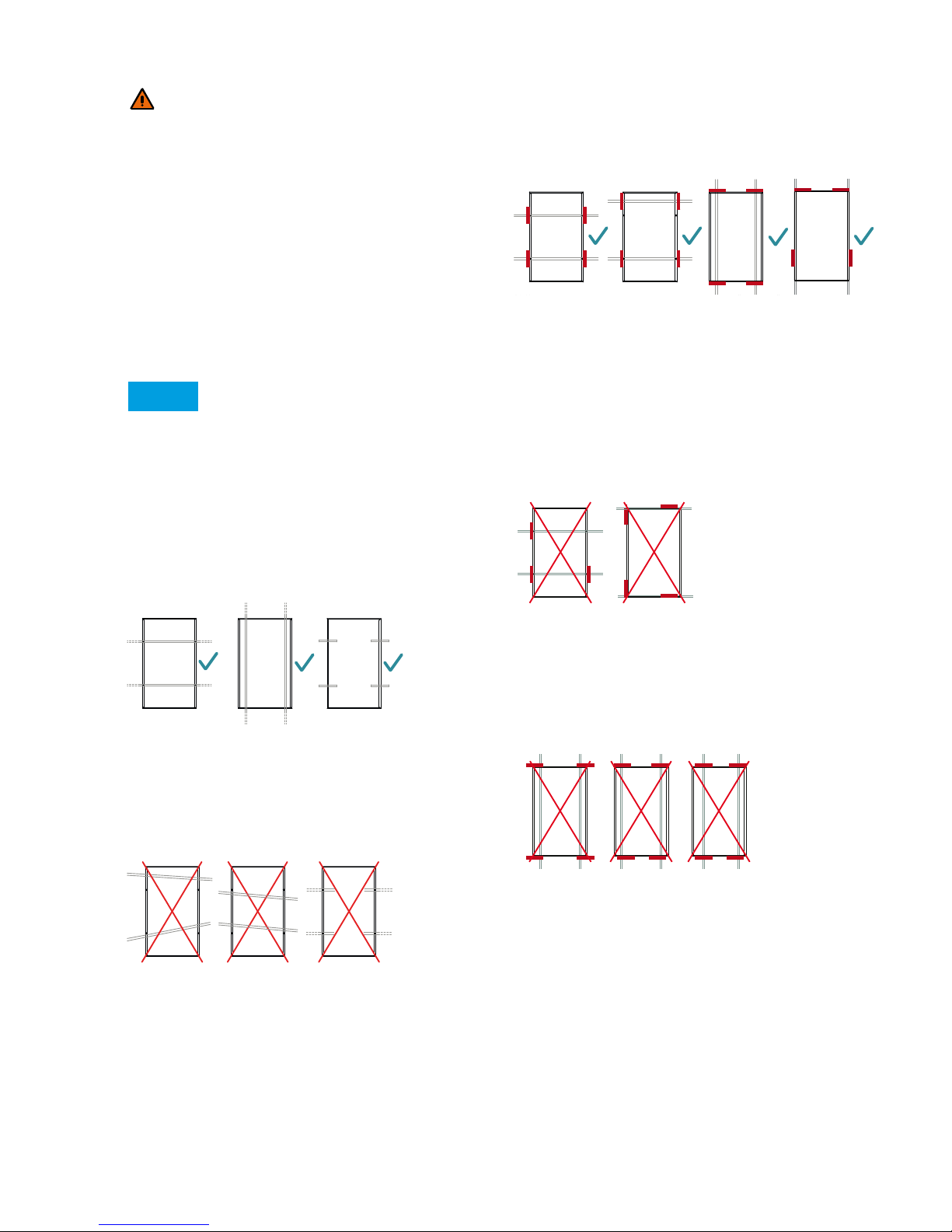
■ Impermissible arrangement
Fig.6 55 Impermissible clamp arrangement for framed
modulesPermissible clamp arrangement for
framed modules
Impermissible clamp arrangement for framed modules (1)
a: Missing clamps,
b: Clamping on both short and long sides.
Fig.7 Impermissible clamp arrangement for framed
modules (2)
d: Protruding clamps,
e: Opposing clamps have
different distances to the module corners,
f: Asymmetrical clamps on the short sides.
10.2.2 Clamp dimensions
Observe the following information for clamp lengths and
depths.
9.4 Lightning protection
WARNING!
Absence of or inadequate lightning protection.
Riskofreorelectricshock!
• Leavetheplanningandinstallationoftheexternal,
and if required internal, lightning protection to be
carried out by qualified technicians at all times.
• Itisessentialtointegrateanarrestorforconnecting
the lightning rod with the lightning protection. This
ensures the safety and reliability of the lightning
protection as well as the photovoltaic system.
• Donotunderanycircumstancesincludethemodule
frame or its earth as an active part of the lightning
protection (e.g. as a lightning arrestor).
_______________________________________________
NOTE
If you earth the module frame, the only task of this
earth is the potential equalisation between the mo-
dule frame and the supporting structure.
10 Details of mechanical mounting
10.1 Aligningthemountingproles
10.1.1 Permissible alignment
Fig.3 Permissible alignment of mounting profiles
a, b: Parallel profiles for mounting; c: Parallel, aligned
fingers of a mounting system.
10.1.2 Impermissible alignment
Fig.4 Impermissible alignment of mounting profiles
a: Profiles not parallel to one another;
b: Profiles neither parallel nor perpendicular to the
module edges;
c: The profile ends for the sides of a module are not
connected.
aleo solar GmbH | Marius-Eriksen-Straße 1 | 17291 Prenzlau | Germany | [email protected] Page 10/19 Quick Reference Manual Rel. 3.0, 07/2014, en-GB-DE (1)
9.4 Lightning protection
WARNING!
Absence of or inadequate lightning protection.
Risk of fire or electric shock!
• Leave the planning and installation of the external,
and if required internal, lightning protection to be
carried out by qualified technicians at all times.
• It is essential to integrate an arrestor for connecting
the lightning rod with the lightning protection. This
ensures the safety and reliability of the lightning pro-
tection as well as the photovoltaic system.
• Do not under any circumstances include the module
frame or its earth as an active part of the lightning
protection (e.g. as a lightning arrestor).
NOTE
If you earth the module frame, the only task of this
earth is the potential equalisation between the mod-
ule frame and the supporting structure.
10 Details of mechanical mounting
10.1 Aligning the mounting profiles
10.1.1 Permissible alignment
Fig.3 Permissible alignment of mounting profiles
a, b: Parallel profiles for mounting; c: Parallel, aligned
fingers of a mounting system.
10.1.2 Impermissible alignment
Fig.4 Impermissible alignment of mounting profiles
a: Profiles not parallel to one another; b: Profiles neither par-
allel nor perpendicular to the module edges; c: The profile
ends for the sides of a module are not connected.
10.2 Clamp mounting for modules with standard
frames
10.2.1 Arranging the clamps
■ Permissible arrangement
Fig.5 55Permissible clamp arrangement for framed
modules
a: Symmetrical clamping on the long sides, b: Asymmetrical
clamping on the long sides (acceptable for certain load
levels), c: Symmetrical clamping on the short sides.
■ Impermissible arrangement
Fig.6 55Impermissible clamp arrangement for framed
modulesPermissible clamp arrangement for
framed modules
Impermissible clamp arrangement for framed modules
(1)a: Missing clamps, b, c: Clamping on both short and long
sides.
Fig.7 Impermissible clamp arrangement for framed
modules (2)
d: Protruding clamps, e: Opposing clamps have different
distances to the module corners, f: Asymmetrical clamps on
the short sides.
10.2.2 Clamp dimensions
Observe the following information for clamp lengths and
depths.
GID AS023b
a b c
a b c
GID AS024a
GID AS025b
ab c
d e f
GID AS069b
aleo solar GmbH | Marius-Eriksen-Straße 1 | 17291 Prenzlau | Germany | [email protected] Page 10/19 Quick Reference Manual Rel. 3.0, 07/2014, en-GB-DE (1)
9.4 Lightning protection
WARNING!
Absence of or inadequate lightning protection.
Risk of fire or electric shock!
• Leave the planning and installation of the external,
and if required internal, lightning protection to be
carried out by qualified technicians at all times.
• It is essential to integrate an arrestor for connecting
the lightning rod with the lightning protection. This
ensures the safety and reliability of the lightning pro-
tection as well as the photovoltaic system.
• Do not under any circumstances include the module
frame or its earth as an active part of the lightning
protection (e.g. as a lightning arrestor).
NOTE
If you earth the module frame, the only task of this
earth is the potential equalisation between the mod-
ule frame and the supporting structure.
10 Details of mechanical mounting
10.1 Aligning the mounting profiles
10.1.1 Permissible alignment
Fig.3 Permissible alignment of mounting profiles
a, b: Parallel profiles for mounting; c: Parallel, aligned
fingers of a mounting system.
10.1.2 Impermissible alignment
Fig.4 Impermissible alignment of mounting profiles
a: Profiles not parallel to one another; b: Profiles neither par-
allel nor perpendicular to the module edges; c: The profile
ends for the sides of a module are not connected.
10.2 Clamp mounting for modules with standard
frames
10.2.1 Arranging the clamps
■ Permissible arrangement
Fig.5 55Permissible clamp arrangement for framed
modules
a: Symmetrical clamping on the long sides, b: Asymmetrical
clamping on the long sides (acceptable for certain load
levels), c: Symmetrical clamping on the short sides.
■ Impermissible arrangement
Fig.6 55Impermissible clamp arrangement for framed
modulesPermissible clamp arrangement for
framed modules
Impermissible clamp arrangement for framed modules
(1)a: Missing clamps, b, c: Clamping on both short and long
sides.
Fig.7 Impermissible clamp arrangement for framed
modules (2)
d: Protruding clamps, e: Opposing clamps have different
distances to the module corners, f: Asymmetrical clamps on
the short sides.
10.2.2 Clamp dimensions
Observe the following information for clamp lengths and
depths.
GID AS022b
a b c
a b c
GID AS024a
GID AS025b
ab c
d e f
GID AS069b
aleo solar GmbH | Marius-Eriksen-Straße 1 | 17291 Prenzlau | Germany | [email protected] Page 10/19 Quick Reference Manual Rel. 3.0, 07/2014, en-GB-DE (1)
9.4 Lightning protection
WARNING!
Absence of or inadequate lightning protection.
Risk of fire or electric shock!
• Leave the planning and installation of the external,
and if required internal, lightning protection to be
carried out by qualified technicians at all times.
• It is essential to integrate an arrestor for connecting
the lightning rod with the lightning protection. This
ensures the safety and reliability of the lightning pro-
tection as well as the photovoltaic system.
• Do not under any circumstances include the module
frame or its earth as an active part of the lightning
protection (e.g. as a lightning arrestor).
NOTE
If you earth the module frame, the only task of this
earth is the potential equalisation between the mod-
ule frame and the supporting structure.
10 Details of mechanical mounting
10.1 Aligning the mounting profiles
10.1.1 Permissible alignment
Fig.3 Permissible alignment of mounting profiles
a, b: Parallel profiles for mounting; c: Parallel, aligned
fingers of a mounting system.
10.1.2 Impermissible alignment
Fig.4 Impermissible alignment of mounting profiles
a: Profiles not parallel to one another; b: Profiles neither par-
allel nor perpendicular to the module edges; c: The profile
ends for the sides of a module are not connected.
10.2 Clamp mounting for modules with standard
frames
10.2.1 Arranging the clamps
■ Permissible arrangement
Fig.5 55Permissible clamp arrangement for framed
modules
a: Symmetrical clamping on the long sides, b: Asymmetrical
clamping on the long sides (acceptable for certain load
levels), c: Symmetrical clamping on the short sides.
■ Impermissible arrangement
Fig.6 55Impermissible clamp arrangement for framed
modulesPermissible clamp arrangement for
framed modules
Impermissible clamp arrangement for framed modules
(1)a: Missing clamps, b, c: Clamping on both short and long
sides.
Fig.7 Impermissible clamp arrangement for framed
modules (2)
d: Protruding clamps, e: Opposing clamps have different
distances to the module corners, f: Asymmetrical clamps on
the short sides.
10.2.2 Clamp dimensions
Observe the following information for clamp lengths and
depths.
GID AS022b
a b c
GID AS023b
a b c
a b c
GID AS024a
GID AS025b
ab c
d e f
GID AS069b
aleo solar GmbH | Marius-Eriksen-Straße 1 | 17291 Prenzlau | Germany | [email protected] Page 10/19 Quick Reference Manual Rel. 3.0, 07/2014, en-GB-DE (1)
9.4 Lightning protection
WARNING!
Absence of or inadequate lightning protection.
Risk of fire or electric shock!
• Leave the planning and installation of the external,
and if required internal, lightning protection to be
carried out by qualified technicians at all times.
• It is essential to integrate an arrestor for connecting
the lightning rod with the lightning protection. This
ensures the safety and reliability of the lightning pro-
tection as well as the photovoltaic system.
• Do not under any circumstances include the module
frame or its earth as an active part of the lightning
protection (e.g. as a lightning arrestor).
NOTE
If you earth the module frame, the only task of this
earth is the potential equalisation between the mod-
ule frame and the supporting structure.
10 Details of mechanical mounting
10.1 Aligning the mounting profiles
10.1.1 Permissible alignment
Fig.3 Permissible alignment of mounting profiles
a, b: Parallel profiles for mounting; c: Parallel, aligned
fingers of a mounting system.
10.1.2 Impermissible alignment
Fig.4 Impermissible alignment of mounting profiles
a: Profiles not parallel to one another; b: Profiles neither par-
allel nor perpendicular to the module edges; c: The profile
ends for the sides of a module are not connected.
10.2 Clamp mounting for modules with standard
frames
10.2.1 Arranging the clamps
■ Permissible arrangement
Fig.5 55Permissible clamp arrangement for framed
modules
a: Symmetrical clamping on the long sides, b: Asymmetrical
clamping on the long sides (acceptable for certain load
levels), c: Symmetrical clamping on the short sides.
■ Impermissible arrangement
Fig.6 55Impermissible clamp arrangement for framed
modulesPermissible clamp arrangement for
framed modules
Impermissible clamp arrangement for framed modules
(1)a: Missing clamps, b, c: Clamping on both short and long
sides.
Fig.7 Impermissible clamp arrangement for framed
modules (2)
d: Protruding clamps, e: Opposing clamps have different
distances to the module corners, f: Asymmetrical clamps on
the short sides.
10.2.2 Clamp dimensions
Observe the following information for clamp lengths and
depths.
GID AS022b
a b c
GID AS023b
a b c
a b c
GID AS024a
GID AS025b
ab c
aleo solar GmbH | Marius-Eriksen-Straße 1 | 17291 Prenzlau | Germany | [email protected] Page 10/19 Quick Reference Manual Rel. 3.0, 07/2014, en-GB-DE (1)
9.4 Lightning protection
WARNING!
Absence of or inadequate lightning protection.
Risk of fire or electric shock!
• Leave the planning and installation of the external,
and if required internal, lightning protection to be
carried out by qualified technicians at all times.
• It is essential to integrate an arrestor for connecting
the lightning rod with the lightning protection. This
ensures the safety and reliability of the lightning pro-
tection as well as the photovoltaic system.
• Do not under any circumstances include the module
frame or its earth as an active part of the lightning
protection (e.g. as a lightning arrestor).
NOTE
If you earth the module frame, the only task of this
earth is the potential equalisation between the mod-
ule frame and the supporting structure.
10 Details of mechanical mounting
10.1 Aligning the mounting profiles
10.1.1 Permissible alignment
Fig.3 Permissible alignment of mounting profiles
a, b: Parallel profiles for mounting; c: Parallel, aligned
fingers of a mounting system.
10.1.2 Impermissible alignment
Fig.4 Impermissible alignment of mounting profiles
a: Profiles not parallel to one another; b: Profiles neither par-
allel nor perpendicular to the module edges; c: The profile
ends for the sides of a module are not connected.
10.2 Clamp mounting for modules with standard
frames
10.2.1 Arranging the clamps
■ Permissible arrangement
Fig.5 55Permissible clamp arrangement for framed
modules
a: Symmetrical clamping on the long sides, b: Asymmetrical
clamping on the long sides (acceptable for certain load
levels), c: Symmetrical clamping on the short sides.
■ Impermissible arrangement
Fig.6 55Impermissible clamp arrangement for framed
modulesPermissible clamp arrangement for
framed modules
Impermissible clamp arrangement for framed modules
(1)a: Missing clamps, b, c: Clamping on both short and long
sides.
Fig.7 Impermissible clamp arrangement for framed
modules (2)
d: Protruding clamps, e: Opposing clamps have different
distances to the module corners, f: Asymmetrical clamps on
the short sides.
10.2.2 Clamp dimensions
Observe the following information for clamp lengths and
depths.
GID AS022b
a b c
GID AS023b
a b c
a b c
GID AS025b
ab c
d e f
GID AS069b
aleo solar GmbH | Marius-Eriksen-Straße 1 | 17291 Prenzlau | Germany | [email protected] Page 10/19 Quick Reference Manual Rel. 3.0, 07/2014, en-GB-DE (1)
9.4 Lightning protection
WARNING!
Absence of or inadequate lightning protection.
Risk of fire or electric shock!
• Leave the planning and installation of the external,
and if required internal, lightning protection to be
carried out by qualified technicians at all times.
• It is essential to integrate an arrestor for connecting
the lightning rod with the lightning protection. This
ensures the safety and reliability of the lightning pro-
tection as well as the photovoltaic system.
• Do not under any circumstances include the module
frame or its earth as an active part of the lightning
protection (e.g. as a lightning arrestor).
NOTE
If you earth the module frame, the only task of this
earth is the potential equalisation between the mod-
ule frame and the supporting structure.
10 Details of mechanical mounting
10.1 Aligning the mounting profiles
10.1.1 Permissible alignment
Fig.3 Permissible alignment of mounting profiles
a, b: Parallel profiles for mounting; c: Parallel, aligned
fingers of a mounting system.
10.1.2 Impermissible alignment
Fig.4 Impermissible alignment of mounting profiles
a: Profiles not parallel to one another; b: Profiles neither par-
allel nor perpendicular to the module edges; c: The profile
ends for the sides of a module are not connected.
10.2 Clamp mounting for modules with standard
frames
10.2.1 Arranging the clamps
■ Permissible arrangement
Fig.5 55Permissible clamp arrangement for framed
modules
a: Symmetrical clamping on the long sides, b: Asymmetrical
clamping on the long sides (acceptable for certain load
levels), c: Symmetrical clamping on the short sides.
■ Impermissible arrangement
Fig.6 55Impermissible clamp arrangement for framed
modulesPermissible clamp arrangement for
framed modules
Impermissible clamp arrangement for framed modules
(1)a: Missing clamps, b, c: Clamping on both short and long
sides.
Fig.7 Impermissible clamp arrangement for framed
modules (2)
d: Protruding clamps, e: Opposing clamps have different
distances to the module corners, f: Asymmetrical clamps on
the short sides.
10.2.2 Clamp dimensions
Observe the following information for clamp lengths and
depths.
GID AS022b
a b c
GID AS023b
a b c
a b c
GID AS024a
GID AS025b
ab
aleo solar GmbH | Marius-Eriksen-Straße 1 | 17291 Prenzlau | Germany | [email protected] Page 10/19 Quick Reference Manual Rel. 3.0, 07/2014, en-GB-DE (1)
9.4 Lightning protection
WARNING!
Absence of or inadequate lightning protection.
Risk of fire or electric shock!
• Leave the planning and installation of the external,
and if required internal, lightning protection to be
carried out by qualified technicians at all times.
• It is essential to integrate an arrestor for connecting
the lightning rod with the lightning protection. This
ensures the safety and reliability of the lightning pro-
tection as well as the photovoltaic system.
• Do not under any circumstances include the module
frame or its earth as an active part of the lightning
protection (e.g. as a lightning arrestor).
NOTE
If you earth the module frame, the only task of this
earth is the potential equalisation between the mod-
ule frame and the supporting structure.
10 Details of mechanical mounting
10.1 Aligning the mounting profiles
10.1.1 Permissible alignment
Fig.3 Permissible alignment of mounting profiles
a, b: Parallel profiles for mounting; c: Parallel, aligned
fingers of a mounting system.
10.1.2 Impermissible alignment
Fig.4 Impermissible alignment of mounting profiles
a: Profiles not parallel to one another; b: Profiles neither par-
allel nor perpendicular to the module edges; c: The profile
ends for the sides of a module are not connected.
10.2 Clamp mounting for modules with standard
frames
10.2.1 Arranging the clamps
■ Permissible arrangement
Fig.5 55Permissible clamp arrangement for framed
modules
a: Symmetrical clamping on the long sides, b: Asymmetrical
clamping on the long sides (acceptable for certain load
levels), c: Symmetrical clamping on the short sides.
■ Impermissible arrangement
Fig.6 55Impermissible clamp arrangement for framed
modulesPermissible clamp arrangement for
framed modules
Impermissible clamp arrangement for framed modules
(1)a: Missing clamps, b, c: Clamping on both short and long
sides.
Fig.7 Impermissible clamp arrangement for framed
modules (2)
d: Protruding clamps, e: Opposing clamps have different
distances to the module corners, f: Asymmetrical clamps on
the short sides.
10.2.2 Clamp dimensions
Observe the following information for clamp lengths and
depths.
GID AS022b
a b c
GID AS023b
a b c
a b c
GID AS024a
GID AS025b
a
aleo solar GmbH | Marius-Eriksen-Straße 1 | 17291 Prenzlau | Germany | [email protected] Page 10/19 Quick Reference Manual Rel. 3.0, 07/2014, en-GB-DE (1)
9.4 Lightning protection
WARNING!
Absence of or inadequate lightning protection.
Risk of fire or electric shock!
• Leave the planning and installation of the external,
and if required internal, lightning protection to be
carried out by qualified technicians at all times.
• It is essential to integrate an arrestor for connecting
the lightning rod with the lightning protection. This
ensures the safety and reliability of the lightning pro-
tection as well as the photovoltaic system.
• Do not under any circumstances include the module
frame or its earth as an active part of the lightning
protection (e.g. as a lightning arrestor).
NOTE
If you earth the module frame, the only task of this
earth is the potential equalisation between the mod-
ule frame and the supporting structure.
10 Details of mechanical mounting
10.1 Aligning the mounting profiles
10.1.1 Permissible alignment
Fig.3 Permissible alignment of mounting profiles
a, b: Parallel profiles for mounting; c: Parallel, aligned
fingers of a mounting system.
10.1.2 Impermissible alignment
Fig.4 Impermissible alignment of mounting profiles
a: Profiles not parallel to one another; b: Profiles neither par-
allel nor perpendicular to the module edges; c: The profile
ends for the sides of a module are not connected.
10.2 Clamp mounting for modules with standard
frames
10.2.1 Arranging the clamps
■ Permissible arrangement
Fig.5 55Permissible clamp arrangement for framed
modules
a: Symmetrical clamping on the long sides, b: Asymmetrical
clamping on the long sides (acceptable for certain load
levels), c: Symmetrical clamping on the short sides.
■ Impermissible arrangement
Fig.6 55Impermissible clamp arrangement for framed
modulesPermissible clamp arrangement for
framed modules
Impermissible clamp arrangement for framed modules
(1)a: Missing clamps, b, c: Clamping on both short and long
sides.
Fig.7 Impermissible clamp arrangement for framed
modules (2)
d: Protruding clamps, e: Opposing clamps have different
distances to the module corners, f: Asymmetrical clamps on
the short sides.
10.2.2 Clamp dimensions
Observe the following information for clamp lengths and
depths.
GID AS022b
a b c
GID AS023b
a b c
a b c
GID AS024a
GID AS025b
ab c
d e f
GID AS069b