Alert-it Care Systems P163 Series User manual

Alert-it Care Systems
P163xxA General Alarm Monitor
(radio)
Handbook
One of a range of Alert-it Care
Alarms available from:
Models covered by this handbook
P163ACA
Radio Touch-iT Monitor
P163BAA
Radio Sense-iT Bed/Chair Vacation Monitor
P163BCA
Radio Sense-iT Switch input

UH1142 P163 General Interface page 2 of 8 UH1142 P163 General Interface page 2 of 8
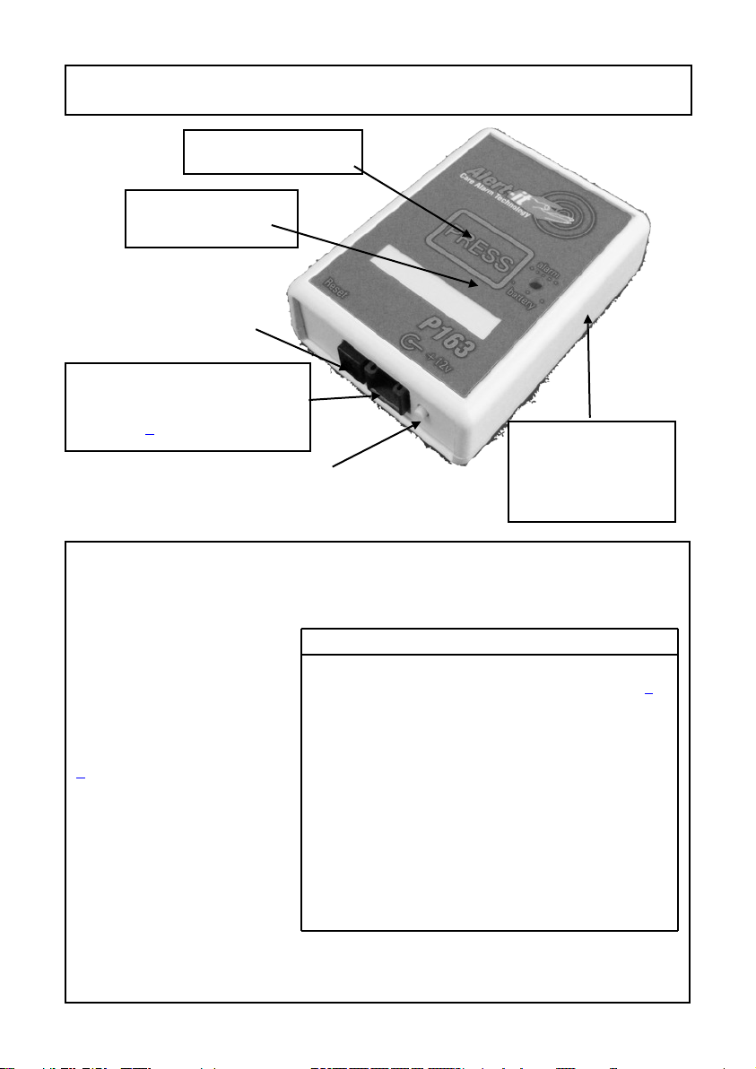
The P163 is a general purpose sensor monitor designed to operate with the Alert-it
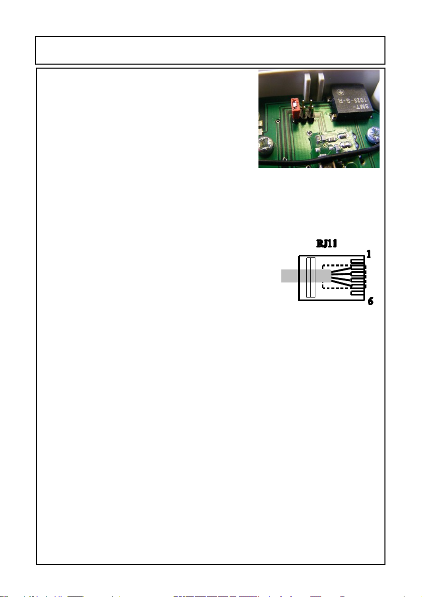
Pagers (P137 or P138). The has two inputs via a RJ12 (Telephone Style) connector.
The function of these inputs is highly programmable, but three standard products
exist. All units offer a front panel CALL button to allow the user to call for
assistance. In health critical applications the monitor can use the failsafe features of
Safelink (see Page {Ref})
P163BAA Bed/Chair Vacation Monitor
This unit is designed to work with a range of Bed/Chair Occupancy sensors, which
are characterised as being switches normally close while the user is present. One
input triggers an instant alarm while the other an alarm after a programmed delay,
with a default of 6 minutes. An internal link can join both inputs so the sensor
activates both functions (default)
It is intended to support the care of those who are frail, vulnerable to falls or
wandering, where the carer needs to know if they leave the bed/chair or fail to
return within an acceptable period. Optionally the unit can be programmed to also
alarm if the resident remains seated for more than 2 hours and hence needs to be
moved.
P163BCA Switch Input Monitor
This unit is designed to work with any switch which closes to trigger an alarm.
Again there is the capability to trigger the alarm instantly or after a delay. In the
case the delay default is 5 seconds. An internal link can join both inputs so the
sensor activates both functions (default)
It is intended to be used by those with restricted mobility who need to use one of a
range of commercially available switches to call their carer. The delay can be set so
a short press send a low level ASSIST alarm and a long press sends an URGENT
alarm. It can also be triggered by Floor Mats to warn when a user is mobile.
P163ACA Touch-iT
The unit is similar to the P163BCA but the CALL button is a proximity sensor
operated by the close presence of a body part, i.e. it needs no force to operate. It is
intended to assist those with severe loss of muscle or nerve control.
Power for P163
While usually powered from batteries, a mains adapter can be used and a
rechargeable version can also be supplied. The rechargeable option has no power
key and the RESET button must be pressed for 5 seconds on first installation to
switch on the stand-by battery, after which the battery is always active if the mains
power fails
This handbook is intended to assist carers install, configure and use the monitors.
The carer therefore needs to understand the needs of the user and asses that the
monitor meets those needs and if any supplementary monitoring is needed taking
into account any health risks.

UH1142 P163 General Interface page 3 of 8 UH1142 P163 General Interface page 3 of 8
Quick Reference Sheet: Installation
RESET and standby power enable
for rechargeable versions
Slide open door
under unit to
replace batteries
12v power supply or
power off key on non-
rechargeable versions
Connection for sensors (bed
mats, floor mats, or switches.
See page 7for pinout
Alarm Indicator
Call for assistance
The standard range of sensors are fitted with a connector to mate with the front
connector. See the individual sensor handbooks for operating instructions. There
are no electrical safety implications for using alternative sensors with battery
operated versions.The
installer must, however,
ensure the sensor meets the
needs of the user and poses
no mechanical or biological
hazard to him. For
connections details see page
7.
Range test.
The unit and pager should be
tested in all the usual
locations to prove signal
reception. A short press (less
than 1sec) of the RESET
button will cause the P163 to transmit a signal. The pager should respond by
showing NODE 00 (or the name allocated to the unit) on the display for 1 second.
See page {Ref} for details of enabling failsafe operation
Accessories available
Part Description Part No Cleaning
See p 6
Bed Occupancy Mat P143C A
Bed Occupancy Ribbon P143G A
Bed Leg Sensor P144A B
Chair Occupancy Ribbon P149B A
Power Supply P171 C
Floor Mat P150 A
Mounting bracket P159A B
Pager P138B B
Power Supply for Pager P153* C

UH1142 P163 General Interface page 4 of 8 UH1142 P163 General Interface page 4 of 8
Operation
The monitor is turned on by
ŸRemoving the power key for battery power
ŸConnecting a mains adapter if required
ŸOr its is always available if the rechargeable battery has
been fitted and enabled
Operating the P163:
Call for Assistance (all versions)
Activating the call button for longer than 1 second will result in
an ASSIST alarm with audible warning on the pager, and a beep from the P163
monitor. Activating for longer than 5 seconds will result in a second beep and the
alarm will be elevated to URGENT. The alarm has to be RESET by the carer as
below
P163BAA Bed/Chair Vacation
After power-up (or RESET) the monitor will be in STANDBY. When the
Occupancy sensor is activated there will be a beep (default) and the monitor will
Sensor Testing
Occupancy Sensors
Ensure the bed/chair is unoccupied and after pressing RESET there will be a four
tone beep and the unit should be in STANDBY. Five tones will indicate the sensor
is being falsely triggered by the weight of the bedding/cushion or otherwise in-
stalled incorrectly.
Activate the sensor and a single beep should be heard indicate successful detection
of the occupant. After that operation is silent.
Deactivating the sensor will then raise the alarm, either instantly or after the delay
period (it is not essential to wait for this as the above proves the senor operation).
Reset the unit to stop further nuisance alarms
Switch Sensors
After RESET there should be no alarm. Activate the sensor and check an alarm is
raised. There is an optional beep when the sensor is activated (i.e. usually for
switch inputs but not for floor mats).
These tests should be performed regularly to confirm correct system operation
All parts of the system, apart from the pager charger, are suitable for use within the patient vicinity
Installation (cont)

UH1142 P163 General Interface page 5 of 8 UH1142 P163 General Interface page 5 of 8
become active. When the user leaves the bed/chair, the monitor will send an
URGENT alarm (either immediately or after a time delay dependent on the “1-
Input Link” (see page 8). The alarm will automatically reset if the user returns to
bed/chair.
To special order the monitor can be programmed to play a warning tune for 30
seconds prior to sending the alarm
P163BCA Switch Input
Activating an external switch will result the same function as for the Call for
Assistance above. The alarm has to be RESET by the carer as below
Reset the Alarm
To reset the alarm it is necessary to press the RESET button for greater than 1
second (until a beep is heard).
Version P163BAA will enter the standby state until the user reappears in the bed or
chair later.
Turn off P163
The unit is supplied with a small RED tagged key. Insert this into the front power
socket to turn the unit off and prevent alarms being detected. If a mains power
adapter is used, then this can be disconnected to isolate the monitor.
The rechargeable version can only be turned off be removing the standby battery,
which can then be replaced. The unit will then stay dormant until the RESET
button is pressed (to cause a beep).
Operation (cont)
Alarm indication on monitor and at the pager/receiver
Alarm Detect Delay P163 Pager
Call Instant Flash Assist 01 Intermittent tune + alarm
Call 5 seconds Flash Urgent 01 Continuous tune + alarm
External
(Instant)
Instant Flash Urgent 01 Continuous tune + alarm
External
(Delayed)
6 minutes Flash Urgent 02 Continuous tune + alarm
TEST Press HELP Flash Shows node name
Battery Low - Flash every 8
sec
Fault 30 Intermittent tune,+ alarm
Battery Fail - Flash every 8
sec
Fault 31 Intermittent tune,+ alarm
Battery
Dead
The P163 beeps every 0.5 sec with no LED and no transmission

UH1142 P163 General Interface page 6 of 8 UH1142 P163 General Interface page 6 of 8
Maintenance
Battery Replacement
The battery needs replacing when FAULT 30 or 31 shows on the P137/8 pager
(and the alarm led flashes intermittently every 8 seconds). The P163 will continue
to function for some hours, allowing time for this replacement. If the battery is
exhausted then the P163 will click continuously without the light flashing or
transmitting.
The battery check is automatic in Securelink mode, or stimulated by making a short
press of the RESET button. This should be done daily to test the battery. The
batteries are found inside the compartment via the sliding door on the base (see
page 3)
Battery Type: 2 of AA Alkaline Batteries or equivalent
Cleaning:
The following is a general guide line based on the components listed on page 3. Where a
different sensor has been supplied, then please refer to the cleaning instructions supplied
with that sensor.
Technique A
Wetting with strong disinfectant. This can include immersion provided plugs and any
obvious breathing holes are avoided.
Technique B
Wiping with cotton wool pads moistened (compressed until dripping stops) with a
mild detergent (0.5% washing up liquid) solution.
Technique C
Wiping with disposable 70% isopropyl alcohol wipes. Ensure that any plugs are
completely dry before reinserting into the sensor input socket on the monitor.
Technique D
Full immersion in detergent , water and optional disinfectant. See component
washing instructions for details
Expected Battery Life: Operating Mode Battery capacity
No failsafe heartbeat, no alarms 1 year
Fail safe heartbeat, and alarms 6 months
Maximum alarm number (based on 2 min response) 2000 alarms

UH1142 P163 General Interface page 7 of 8 UH1142 P163 General Interface page 7 of 8
Securelink Mode
In Safelink the monitor will send a radio “heartbeat”
signal every 10 seconds. If this signal disappears for
more than 2 minutes, the pager will issue an “RF
Fail” alarm. This mode will decrease battery life but
is essential in any health critical application
The default setting is without Securelink (as
shown). To enable the failesafe mode refit the link
to the centre pins AND CYCLE POWER (which will require removing/replacing
any rechargeable batteries)
Input Connections
The connection details
for the unit are shown
above and, in general,
the alarms will be
activated when a
connection is made
from pin 2 or pin 3 to
0v (pin 4 or 5).
Pin 3 causes instant
transmission of the
alarm, while pin 2 will
delay transmission for a time that will have been programmed into the unit. The
internal 1-Input link joins pin 2 & 3 so that any input causes an instant alarm
followed by a delayed alarm.
Configuration Changes
The monitor uses the standard Alert-iT Programming Data Protocol and all the
main features can be changed using the P152 USB Interface and Data Editor
Programme.
Communication Address Changes
Each badge in a care home MUST have a different communication address. To
facilitate easy installation the Communication Address can also be changed directly
from the pager using the P173A programming cable
Input connection details
pin Function FCC64
cable
1 +12v (option) Brown
2 Delay in Yellow
3 Instant in Green
4 0v Red
5 0v Black
5 No connection Blue
Technical Information & Configuration

UH1142 P163 General Interface page 8 of 8 UH1142 P163 General Interface page 8 of 8
1-Input Link
The two input s can be joined by this link so that
one level of alarm is INSTANT and a second level
DELAYED. To access this link , remove the 4 case
screws and separate the two halves.
The picture shows the two possible positions for the
Bed/Chair Vacation Alarm.
For the other versions the Delay Only Option is set
by removing the link
P163BAADELAY only
INSTANT + DELAY
Technical Information & Configuration

UH1142 P163 General Interface page 9 of 8 UH1142 P163 General Interface page 9 of 8

UH1142 P163 General Interface page 10 of 8 UH1142 P163 General Interface page 10 of 8

UH1142 P163 General Interface page 11 of 8 UH1142 P163 General Interface page 11 of 8
1. Ensure that the senor cable is routed and secured to avoid the risk of entanglement or
strangulation.
2. Only the recommended power supply shall be used as it is certified to provide two
means of patient protection to EN60601-1in non-hospital environments
3. Consult the manufacturer for power supplies suitable for hospital use
4. Ensure any power cable is routed to avoid a trip hazard
5. Regularly check the power supplies for damage and potential shock risks
6. Clean and disinfect each item regularly in accordance with information herein
7. Regularly test all sensors as described herein
8. Ensure, by testing, that the alarm is annunciated at the carer's location(s)
9. Operate any power supply and charge pager away from direct heat and uncovered.
10. As with all medical electronic equipment there is potential for the equipment to
interfere with or be effected by interference from other electrical or electronic devices.
For this reason avoid placing the monitor, sensor or connecting cable in close proximity
to sensitive electronic devices or devices which produce strong electromagnetic fields
such as radio transmitters, mobile phones or power cables.
11. Only use the monitor with accessories approved for use with this product and only in
accordance with instructions.
12. If the equipment is modified in any way, appropriate inspection and testing must be
conducted to ensure continued safe use of the equipment.
13. The carer must conduct a risk assessment to determine if the level of reliability offered
by the monitor is sufficient or if additional monitoring is needed. Contact the
manufacture for assistance with Risk Evaluation Tools.
14. Additional levels of mechanical protection may be needed for some patient disorders.
Contact the manufacturers for advice
15. Some accessories are fitted with small screws and have plastic bags. Ensure these do
not come into the possession of vulnerable patients who might choke on them
16. Any sensor over the mattress (Bed Vacation) has the potential to cause pressure sores .
The carer must assess this risk and monitor the use of these products
17. Any sensor over the mattress could pose a fire hazard if in contact with a smouldering
cigarette.
18. The monitor and all accessories are designed to operate indoors in a residential
environment of 10ºC to 30ºC and 90%RH max.
This symbol indicates there are warnings and precautions associated with the use of this
equipment that should be carefully read and understood before using the equipment.
!
Safety Instructions and Warnings
Certified as Class 1 Medical,
Class II Electrical Safety

UH1142 P163 General Interface page 12 of 8 UH1142 P163 General Interface page 12 of 8
1Alert-it Care Alarms are social aids designed and manufactured in accordance with
93/42/EEC as Class 1 Medical Devices. They are intended to improve the vigilance of carers
to distressing side-effects of various diseases, such as Epilepsy and Dementia. They do not
monitor vital physiological processes and should not be expected to diagnose any disease or
predict the onset of any symptoms.
The Alert-it system has been designed with due regard to reliability and integrity. While it offers a highly
vigilant monitoring method,it is always possible that a distress condition can go undetected for a variety
of reasons (including malfunction) and in life threatening situations it is advisable to use the Alert-it
system in conjunction with additional monitoring techniques (e.g. video). Neither the manufacturer nor its
agent can accept legal responsibility to provide a system that is infallible. The carer is responsible for
assessing the risks of using this equipment and any settings pertaining to it.
Support
For technical support please fax or EMail:
HELP: 0845 217 9951
FAX :0845 217 9953
...using technology to care for carers
Designed by:
ITs Designs Ltd
Leicester
LE9 9FE UK
Certified as compliant to the following standards
93/42/EEC as revise 2007/47/EC Medical Devices Directive
EN 14971:2007 Risk Assessment
EN 61010-1:2005 Medical Device Safety Requirements
EN12182:1999 Technical Aids for Disabled Persons
EN 61010-1-2:2004 EMC
EN 300 220-1 V2.1.1 (2006-04) Radio Transmissions: Short Range Devices
2002/95/ECRoHS Permitted Materials
Additional Documents
Quick Start Radio Switch System UQ1155
Quick Start Radio Mobility Systems UQ1044
Review of different Occupancy Sensors UL1200
Check sheet on choice of occupancy sensors UT1246
You tube Instruction Videos Index UV1198
This manual suits for next models
3
Table of contents
Other Alert-it Care Systems Security System manuals
Popular Security System manuals by other brands

Stahl
Stahl YA60 Series operating instructions

Perenio
Perenio PEKIT01 Connection guide

Earykong
Earykong PG-103 user manual

Vigilant
Vigilant QE20 installation manual

Tyco Security Products
Tyco Security Products DSC PowerSeries Neo installation guide

Concept Smoke Screen
Concept Smoke Screen TITANIUM Ti70 Installation and operation manual