Alfa Network AlfaBlue BD User manual

ORIGINAL INSTRUCTIONS
9460173342EN-04
AlfaBlue BD
Instruction manual
• Product description
• Product labels
• Unpacking & lifting
• Installation
• Maintenance
• Spare parts

9460173342EN-04
2
Alfa LU-VE is a trademark registered and owned by LU-VE Group.
Alfa LU-VE reserves the right to change specifications without prior notification.
Index
1. Important information
1.1 Disclaimer...................................................................................................................................4
1.2 Intended use...............................................................................................................................4
1.3 Where to nd product information ..............................................................................................4
2. Product description
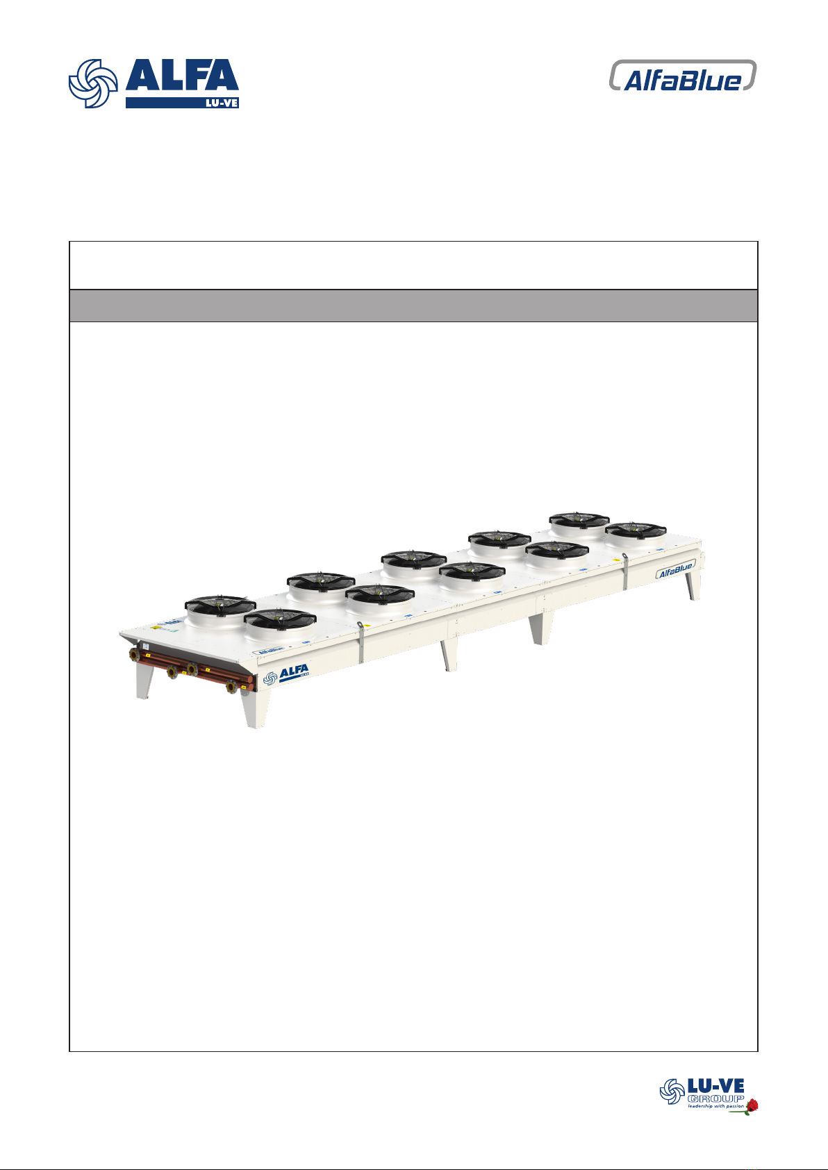
2.1 Introduction.................................................................................................................................5
2.2 Finned coil..................................................................................................................................5
2.3 Construction ...............................................................................................................................5
2.4 Fans ...........................................................................................................................................5
2.5 Optional features........................................................................................................................5
2.6 Code description ........................................................................................................................6
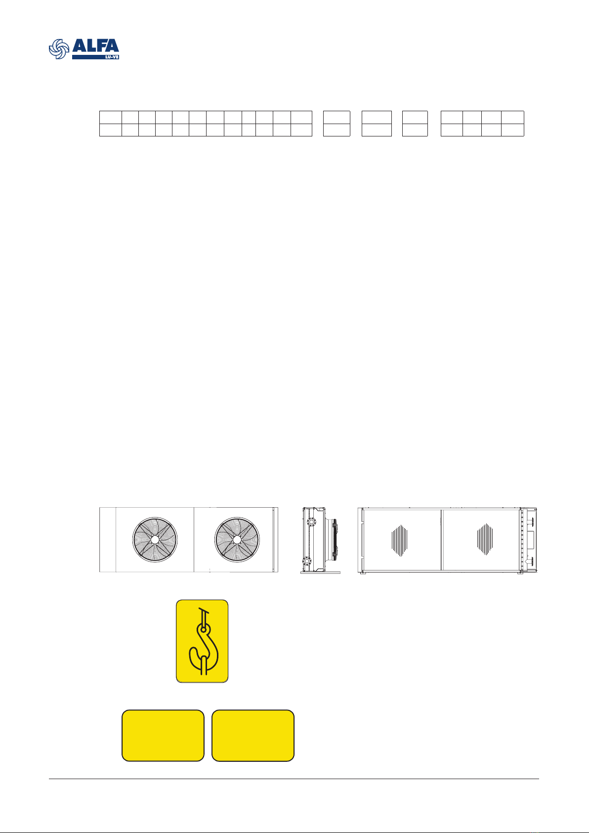
3. Product labels...........................................................................................................................6
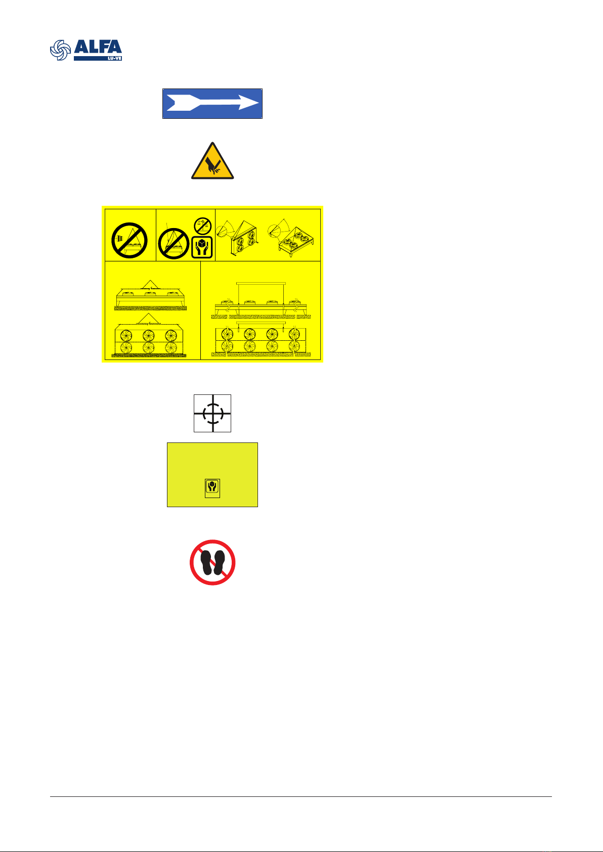
4. Unpacking and lifting
4.1 Packing.....................................................................................................................................10
4.2 Shipping dimensions ................................................................................................................10
4.3 Unpacking ................................................................................................................................11
4.4 Feet mounting for vertical airow .............................................................................................12
4.5 Wind braces for 1200 mm feet .................................................................................................13
4.6 Lifting from above.....................................................................................................................15
5. Installation
5.1 Mounting dimensions BDM 800s horizontal airow, same side connections ...........................16
5.2 Mounting dimensions BDM 800s horizontal airow, opposite side connections ......................17
5.3 Mounting dimensions BDM 800s vertical airow, same side connections ...............................18
5.4 Mounting dimensions BDM 800s vertical airow, opposite side connections ..........................19
5.5 Mounting dimensions BDM 800 horizontal airow, same side connections.............................20
5.6 Mounting dimensions BDM 800 horizontal airow, opposite side connections ........................21
5.7 Mounting dimensions BDM 800 vertical airow, same side connections .................................22
5.8 Mounting dimensions BDM 800 vertical airow, opposite side connections ............................23
5.9 Mounting dimensions BDM 900-1000 horizontal airow, same side connections....................24
5.10 Mounting dimensions BDM 900-1000 horizontal airow, opposite side connections...............25
5.11 Mounting dimensions BDM 900-1000 vertical airow, same side connections........................26
5.12 Mounting dimensions BDM 900-1000 vertical airow, opposite side connections ...................27
5.13 Mounting dimensions BDD 800 horizontal airow, same side connections .............................28
5.14 Mounting dimensions BDD 800 horizontal airow, opposite side connections ........................29
5.15 Mounting dimensions BDD 800 vertical airow, same side connections..................................30
5.16 Mounting dimensions BDD 800 vertical airow, opposite side connections.............................31
5.17 Mounting dimensions BDD 900-1000 horizontal airow, same side connections ....................32
5.18 Mounting dimensions BDD 900-1000 horizontal airow, opposite side connections ...............33
5.19 Mounting dimensions BDD 900-1000 vertical airow, same side connections ........................34
5.20 Mounting dimensions BDD 900-1000 vertical airow, opposite side connections ...................35
5.21 Concrete mounting base ..........................................................................................................36
5.22 Vibration dampers ....................................................................................................................36
5.23 Expansion joints .......................................................................................................................37
5.24 Positioning................................................................................................................................38
5.25 Wind braces for 4-5-6 modules BDD horizontal airow models...............................................40
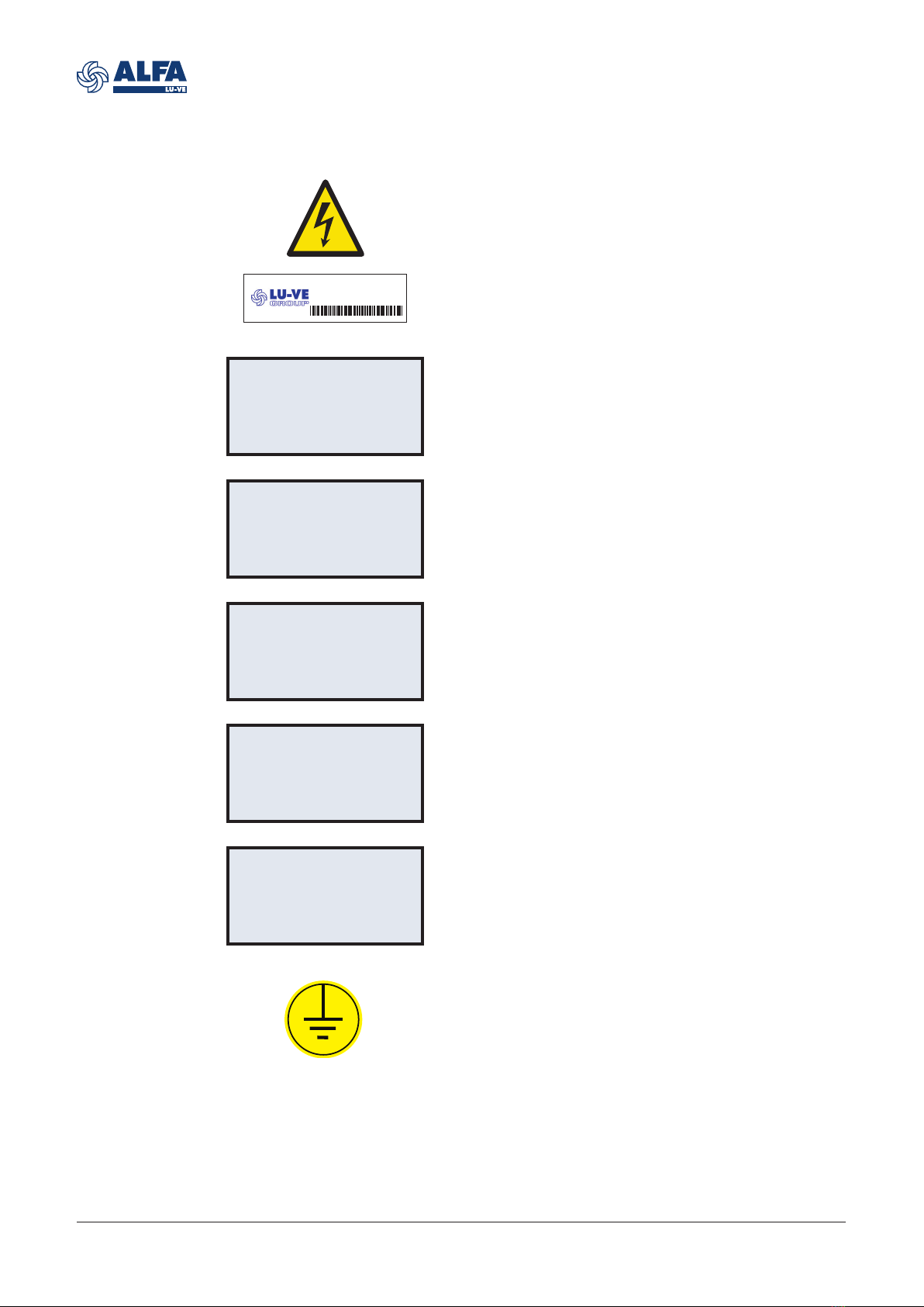
5.26 Electrical connections...............................................................................................................42
5.27 Switchboard..............................................................................................................................42
5.28 Switch on/o (option SW) ........................................................................................................43
5.29 Master controller (options CBMx and ECCBx).........................................................................43

9460173342EN-04
3
Alfa LU-VE is a trademark registered and owned by LU-VE Group.
Alfa LU-VE reserves the right to change specifications without prior notification.
6. Operation
6.1 Start up procedure....................................................................................................................44
6.2 Shutdown .................................................................................................................................44
7. Maintenance
7.1 Fan replacement ......................................................................................................................45
7.2 End covers ...............................................................................................................................45
8. Spare parts..............................................................................................................................46

9460173342EN-04
4
Alfa LU-VE is a trademark registered and owned by LU-VE Group.
Alfa LU-VE reserves the right to change specifications without prior notification.
1 Important information
1.1 Disclaimer
This Instruction Manual applies to all AlfaBlue BD air cooled liquid coolers and is supplied in combi-
nation with the product manual AHE00050. Both manuals must be carefully examined and instruc-
tions should be followed up at all times. Alfa LU-VE does not accept liability for any damage result-
ing from non-compliance to the instructions as given in the manuals and order-related documents.
If there are any inconsistencies between the manual and the technical construction file, the manual
prevails unless explicitly specified.
1.2 Intended use
Air cooled liquid coolers are partly completed machinery according to Machine Directive 2006/42/
EC and intended for incorporation in cooling systems. Declarations of Incorporation are available
on alfa.luvegroup.com. Heat exchanger units may not be put into operation until the conformity of
the complete machine or cooling system has been declared according to the following standards
and directives:
• Pressure Equipment Directive 2014/68/EU
• Machine Directive 2006/42/EC
• Low Voltage Directive 2014/35/EU
• Electrical Equipment of Machines IEC 60204-1
• Electro Magnetic Compatibility 2014/30/EU
• Any applicable local or national legislation
1.3 Where to find product information
Detailed technical data for individual product models are available in order related documents, on
the product sticker and in product data sheets. Comprehensive technical information for all Alfa
LU-VE air heat exchanger products is available on-line on alfa.luvegroup.com. This includes:
• Product manuals
• Instruction manuals
• Product leaflets & brochures
• Product data sheets (selection software)
• Dimensional drawings
• Electrical wiring diagrams
• Certificates
Alfa LU-VE offers world-wide service and support. In case of any questions or uncertainty please
contact your local Alfa LU-VE representative.
Contact addresses are available at alfa.luvegroup.com.
AlfaBlue BD

9460173342EN-04
5
Alfa LU-VE is a trademark registered and owned by LU-VE Group.
Alfa LU-VE reserves the right to change specifications without prior notification.
2 Product description
2.1 Introduction
The AlfaBlue series is a wide range of heavy-duty liquid coolers. Liquid coolers are often used for
cooling down condenser water in air conditioning and refrigeration installations. In the processing
industry, liquid coolers are suitable for closed circuit cooling of various process liquids. With a wide
range of sound pressure level alternatives, these units are particularly suited to demanding, noise
sensitive environments. Available both in single (M) or dual (D) fan row: separate connections in the
dual fan row (D) models provide the opportunity for independent operation of both dry cooler coils.
Dedicated series for compressor oil coolers (BDO).
2.2 Finned coil
An innovative coil design provides excellent heat transfer. In standard execution liquid coolers are
fitted with smooth copper tubing or stainless steel tubing and corrugated aluminium turbo fins for
maximized capacity or industrial power fins for long lasting performance. Available in different fin
thicknesses and fin spacings. Separate connections in the D series provide the opportunity for inde-
pendent operation of both coils.
Model Design pressure
AlfaBlue BD 10 bar
AlfaBlue BDO 30 bar
2.3 Construction
Frame construction provides high rigidity for protection against vibration and thermal expansion.
Casing and framework of corrosion resistant pre-galvanized sheet steel, epoxy powder coated white
RAL 9002. Separated fan sections.
2.4 Fans
High efficiency AC or EC fan motors, available in three fan diameters (800, 910 & 1000 mm) and
several noise levels, power supply 400/50/3. Motors with external rotor, protection class IP 54
according to DIN 40050. Integrated thermo contacts provide reliable protection against thermal
overload.
2.5 Optional features
•Mounting feet for vertical airflow (500 mm, 850 mm and 1200 mm)
• Coil options:
Epoxy pre-painted aluminium fins (EP), seawater resistant aluminium alloy fins (SWR), copper
fins (CU), F-coat treatment (FC)
• Stainless steel tubes
•Vibration dampers (VD)
•Spray water device (KW)
• Electrical options:
- Switch on/off (SW)
- AC Motors wired to a common terminal box (CB)
- Basic Switchboard for AC fans (BS)
- Basic Switchboard for AC fans+ Fan step control (BST)
- EC Motors wired to a common terminal box (CBP)
- EC Motors wired to a common terminal box + master controller + temperature probe (CBMT)
- Basic Switchboard for EC fans (ECCB)
- Basic switchboard for EC fans+ master controller (ECCBM)
- Basic switchboard for EC fans+ master controller+ temperature probe (ECCBMT)
- EC fan speed control cabinet (ICM)
- EC fan speed control cabinet + temperature probe (ICMT)

9460173342EN-04
6
Alfa LU-VE is a trademark registered and owned by LU-VE Group.
Alfa LU-VE reserves the right to change specifications without prior notification.
2.6 Code description
BD M Y S E 80 2 s .2 A D 6 CR Feet * AL 2.1 SS *
1 2 3 4 5 6 7 8 9 10 11 12 13 14 15 16 17 18 19
1 AlfaBlue dry cooler
2 Number of fan rows (M=1, D=2)
3 Dedicated series (blank= default, 6 = 5/8" Cu tubes, Y=SS tubes, O=compressor oil cooler)
4 Sound level (T=turbo, S-standard, L=low, Q=quiet, R=residential)
5 EC fan (blank=AC fan, E=EC fan)
6 Fan diameter (80=800 mm, 90=910, 100=1000 mm)
7 Number of fans per row (1 to 6)
8 Short coil module (s=short coil module, blank=default)
9 Version number
10 Tube rows code (A, B, C, D)
11 Fan motor connection (D=delta, Y=star)
12 Number of circuits
13 Packing (CR=crate, P=pallet, PP=pallet with protection for headers and coil, SK=container
skid)
14 Feet=mounting feet supplied mounted (type of feet according to airflow selected)
blank=Mounting feet supplied loose
15 Electrical accessories
16 Fin material/coating (AL=aluminium, IF=industrial fins, SWR=sea water resistant fins,
EP=epoxy coated alu, FC=F-coat)
17 Fin spacing (2.1, 2.3, 2.5, 3.0)
18 Tube material (CU=copper, SS=stainless steel)
19 Options
3 Product labels
1. Lifting point
Use all marked lifting points when lifting from
above. 4 lifting points available for both horizon-
tal and vertical airflow setup.
2. & 3. In/Out
Liquid connections inlet and outlet.
IN
OUT
①
①
③④
⑥
⑩
⑫
⑬⑪②
⑧
⑬
①
①
⑦
⑤
⑧
⑬
⑨⑨

9460173342EN-04
7
Alfa LU-VE is a trademark registered and owned by LU-VE Group.
Alfa LU-VE reserves the right to change specifications without prior notification.
5. Product label
Model Code description
Item ID
Serial no.
To be communicated when
ordering spare parts as
they identify the unit.
O.A. Order acknowledgement
number
Unit Net Weight Check before any lifting
operation to ensure that
proper lifting tools are
used.
6. Product label - coil
Model Code description
Item ID
Serial no.
To be communicated when
ordering spare parts as
they identify the unit.
Max DN Maximum diameter of the
distributor tube
Fluid Group According to PED
Coil Ts Range of operating tem-
peratures for the coil
Ps Design pressure
Pt Test pressure
Test date Date on which the coil has
been pressure tested in
the factory
WARNING
READ INSTRUCTION MANUAL BEFORE INSTALLATION AND
MAINTENANCE TO AVOID INJURIES OR DAMAGE
Manufacturer Manuf. Date
AIR HEX ALONTE S.R.L. - Italy 04 / 2019
Model O.A. 388483/10
BDDS903CD224 P Feet
AL 2.1 CU
Item ID 3289219820
Serial no. AA 2351392
Sn
Material CU
PED Category Art. 4.3
Volume 16,93 m3
Max DN 127
Fluid Group 2
Coil Ts +110/-60 °C
Ps 10 bar
Pt 15 bar
Test Date 04-2019
EXAMPLE
WARNING
READ INSTRUCTION MANUAL BEFORE INSTALLATION AND
MAINTENANCE TO AVOID INJURIES OR DAMAGE
Manufacturer Manuf. Date
AIR HEX ALONTE S.R.L. - Italy 04 / 2019
Model O.A. 388483/10
BDDS903CD224 P Feet
AL 2.1 CU
Item ID 3289219820
Serial no. AA 2351392
Unit Net Weight 1182 Kg ±5%
Sn
Motorfan data
Vn 3~400V
f 50Hz
Country of origin Italy
EXAMPLE
7. Moving parts
Warning: moving parts.
Switch off power supply before any mainte-
nance or installation activities.
4. Hot surfaces
Warning: danger of burns. Wear adequate pro-
tection. Applied to the INLET header.

9460173342EN-04
8
Alfa LU-VE is a trademark registered and owned by LU-VE Group.
Alfa LU-VE reserves the right to change specifications without prior notification.
8. Fan direction
Sticker indicates fan rotation direction.
10. Lifting instructions
Detailed lifting instructions (see dedicated para-
graph of the manual).
11. & 12. Centre of gravity/Handle with care
When lifting the unit using a forklift, always place
the forks under the center of gravity.
When handling the unit using a forklift, always
take maximum care.
Both stickers are applied on the protective plas-
tic foil covering the units during transportation.
HANDLE
WITH CARE
WITH
HANDLE
CARE
IN WINDY CONDITION IS NOT
RECOMMENDED TO LIFT THE UNIT
CHECK THAT ALL ROPES ARE EQUALLY
LOADED. AVOID VIOLENT TUG
ropes with
high tension
CHAIN ANGLE:
HORIZONTAL INSTALLATION
CHAIN ANGLE:
VERTICAL INSTALLATION
≥60°
≥60°
ALFABLUE 1, 2 AND 3 MODULES:
LIFTING BAR IS NOT NEEDED.
N° 4 EYEBOLTS AT EACH CORNER OF THE UNIT
VALID FOR BOTH SINGLE AND DOUBLE FAN ROW
ALFABLUE 4, 5 AND 6 MODULES:
LIFTING BAR IS COMPULSORY.
N° 4 LIFTING POINTS AT INTERMEDIATE POSITIONS.
VALID FOR BOTH SINGLE AND DOUBLE FAN ROW
13. Do not walk
Don’t walk on the headers or on the fan cowls.
9. Sharp surfaces
Warning: danger of cutting injuries. Wear ade-
quate protection.

9460173342EN-04
9
Alfa LU-VE is a trademark registered and owned by LU-VE Group.
Alfa LU-VE reserves the right to change specifications without prior notification.
CB1
CP
A1
Q1.1
SB
Connection box indentifier
Connection box power. One for each fan row.
Only for units featuring the corresponding option.
Signal box identifier
Connection box for EC fans signal. Only for units
featuring the corresponding option.
Master Controller identifier
Only for units featuring the corresponding option.
Switchboard identifier
Only for units featuring the corresponding option
(ICM/ECCB).
Switch ON/OFF identifier
Only for units featuring the corresponding option
(ICM/ECCB).
Grounding
Whenever electrical components supplied by
Alfa LU-VE have this sticker, is mandatory to
ground them. The yellow/green grounding wire
must be left longer than the others, to ensure
that it is the last one to be detached from the
terminals in the event of the cable being pulled
off. Grounding is designed for the electrical
equipment supplied with the unit and is not to be
intended as protection from external sources.
41103043SP
Spare part item number
Fan motor
Fan motor item number. Located on each fan
motor.
Electrical warning
Electrically powered component. Switch off
power supply before any maintenance or instal-
lation operation.
Stickers on this page are not represented in the stickers overview illustration.

9460173342EN-04
10
Alfa LU-VE is a trademark registered and owned by LU-VE Group.
Alfa LU-VE reserves the right to change specifications without prior notification.
4 Unpacking and lifting
Always follow guidelines and instructions as given in the product manual for air cooled liquid cool-
ers AHE00050.
4.1 Packing
By default, all units are shipped in horizontal airflow position. If vertical airflow is selected, mounting
feet come loose. Units are mounted on a wooden pallet, wrapped with plastic foil. As an optional,
open crate (single fan row models) or protection for headers and coil (dual fan row models) can be
selected. AlfaBlue for vertical airflow can be ordered with mounted feet. These units are shipped in
mounting position with a pallet for on-site handling.
4.2 Shipping dimensions
Dimensions in the table refer to basic units without any option, shipped in horizontal airflow position
with the different packing options available.
Model
Pallet packing
(with and without protections)
Width (m) Height (m) Length (m)
BDM 801s 0.97 1.69 2.25
BDM 802s 0.97 1.69 3.65
BDM 803s 0.97 1.69 5.05
BDM 804s 0.97 1.69 6.45
BDM 805s 0.97 1.69 7.85
BDM 801 1.10 1.71 2.55
BDM 802 1.10 1.71 4.30
BDM 803 1.10 1.71 6.05
BDM 804 1.10 1.71 7.78
BDM 805 1.10 1.71 9.53
BDM 901-1001 1.10 1.71 2.90
BDM 902-1002 1.10 1.71 5.00
BDM 903-1003 1.10 1.71 7.10
BDM 904-1004 1.10 1.71 9.18
BDM 905-1005 1.10 1.71 11.28
BDM 906--1006 1.10 1.71 13.38
BDD 802 1.10 2.52 4.3
BDD 803 1.10 2.52 6.05
BDD 804 1.10 2.52 7.78
BDD 805 1.10 2.52 9.53
BDD 806 1.10 2.52 11.28
BDD 902-1002 1.10 2.52 5
BDD 903-1003 1.10 2.52 7.1
BDD 904-1004 1.10 2.52 9.18
BDD 905-1005 1.10 2.52 11.28
BDD 906-1006 1.10 2.52 13.38
Model
Crate packing
(only for single fan row models)
Width (m) Height (m) Length (m)
BDM 801s 1.09 1.75 2.29
BDM 802s 1.09 1.75 3.69
BDM 803s 1.09 1.75 5.09
BDM 804s 1.09 1.75 6.49
BDM 805s 1.09 1.75 7.89
BDM 801 1.09 1.75 2.64
BDM 802 1.09 1.75 4.39
BDM 803 1.09 1.75 6.14
BDM 804 1.09 1.75 7.89
BDM 805 1.09 1.75 9.64
BDM 901-1001 1.09 1.75 2.99
BDM 902-1002 1.09 1.75 5.09
BDM 903-1003 1.09 1.75 7.19
BDM 904-1004 1.09 1.75 9.29
BDM 905-1005 1.09 1.75 11.39
BDM 906--1006 1.09 1.75 13.49

9460173342EN-04
11
Alfa LU-VE is a trademark registered and owned by LU-VE Group.
Alfa LU-VE reserves the right to change specifications without prior notification.
4.3 Unpacking
The unit is shipped on a pallet, handling can take place with use of a forklift. Remove cover crate or
wooden protections on headers and coil (if present).
Unscrew from pallet.
The unit is now ready to be lifted into mounting
position. During this procedure the operator must
never stand nor walk below the suspended load.

9460173342EN-04
12
Alfa LU-VE is a trademark registered and owned by LU-VE Group.
Alfa LU-VE reserves the right to change specifications without prior notification.
If units designated for vertical airflow have been
ordered with loose feet, the heat exchangers are
packed and shipped in horizontal airflow posi-
tion. Mounting feet must be mounted prior to
installation according to the following procedure.
During this procedure the operator must never
stand nor walk below the suspended load.
1) Lift unit from pallet and tilt 90° onto supports.
Use supports for each mounting foot position.
Supports must span the full casing width to
avoid damages. Supports must be placed under
the load-bearing frame and not under the coil.
2) Remove and reposition lifting eyebolts or lift-
ing stirrups as shown in the illustrations.
3) Remove all mounting profiles.
4) Fit mounting feet on both sides of the casing
at all vacant mounting profile positions.
5) With all mounting feet in place, the unit is
ready for further positioning and installation.
Replace eyebolts Replace stirrup
4.4 Feet mounting for vertical airflow
Lifting eyebolts
Lifting stirrup

9460173342EN-04
13
Alfa LU-VE is a trademark registered and owned by LU-VE Group.
Alfa LU-VE reserves the right to change specifications without prior notification.
4.5 Wind braces for 1200 mm feet
Place and fix the wind braces as shown: each beam has a hole which shall be facing upwards.
BENDS SIDE
CONNECTIONS SIDE
The illustration shows how to mount the wind
braces on the width side of the heat exchanger:
beams shall be mounted alternated in order to
reinforce the structure properly.

9460173342EN-04
14
Alfa LU-VE is a trademark registered and owned by LU-VE Group.
Alfa LU-VE reserves the right to change specifications without prior notification.
The illustration below shows the wind braces positioning on the length side of the heat exchanger.

9460173342EN-04
15
Alfa LU-VE is a trademark registered and owned by LU-VE Group.
Alfa LU-VE reserves the right to change specifications without prior notification.
4.6 Lifting from above
All AlfaBlue models for both horizontal and vertical airflow are fitted with 4 lifting points. Hence
the illustrations apply to all AlfaBlue models for both horizontal and vertical airflow. AlfaBlue heat
exchangers can be lifted from above. Use a hoisting beam when necessary, as indicated.
• Attach belts or hooks to all lifting points.
• Respect the allowable chain angles. The load on the lifting chains shall be equally distributed on
all the lifting points.
• For all models it is mandatory to use all indicated lifting positions during any lifting
operation.
IN WINDY CONDITION IS NOT
RECOMMENDED TO LIFT THE UNIT
CHECK THAT ALL ROPES ARE EQUALLY
LOADED. AVOID VIOLENT TUG
ropes with
high tension
CHAIN ANGLE:
HORIZONTAL INSTALLATION
CHAIN ANGLE:
VERTICAL INSTALLATION
≥60°
≥60°
ALFABLUE 1, 2 AND 3 MODULES:
LIFTING BAR IS NOT NEEDED.
N° 4 EYEBOLTS AT EACH CORNER OF THE UNIT
VALID FOR BOTH SINGLE AND DOUBLE FAN ROW
ALFABLUE 4, 5 AND 6 MODULES:
LIFTING BAR IS COMPULSORY.
N° 4 LIFTING POINTS AT INTERMEDIATE POSITIONS.
VALID FOR BOTH SINGLE AND DOUBLE FAN ROW

9460173342EN-04
16
Alfa LU-VE is a trademark registered and owned by LU-VE Group.
Alfa LU-VE reserves the right to change specifications without prior notification.
5 Installation
Always follow guidelines and instructions as given in the product manual
AHE00050. Detailed drawings showing all required mounting and
refrigerant connection dimensions are available for download on
alfa.luvegroup.com.
5.1 Mounting dimensions BDM 800s horizontal airflow, same side connections
Dimensional drawings
3280*
2800
4680*
4200
7480*
2800 1400 2800
1880*
1400
6080*
2800 2800
1490
950
900
850
feet detail
FIXING POINT
Ø 16
40
120
Switchboard
*+ 60 mm for BDMY (SS tubes)

9460173342EN-04
17
Alfa LU-VE is a trademark registered and owned by LU-VE Group.
Alfa LU-VE reserves the right to change specifications without prior notification.
5.2 Mounting dimensions BDM 800s horizontal airflow, opposite side connections
1490
950
900
850
feet detail
FIXING POINT
Ø 16
40
120
2130
1400
3530
2800
4930
4200
6330
2800 2800
7730
2800 1400 2800
Switchboard

9460173342EN-04
18
Alfa LU-VE is a trademark registered and owned by LU-VE Group.
Alfa LU-VE reserves the right to change specifications without prior notification.
5.3 Mounting dimensions BDM 800s vertical airflow, same side connections
FIXING POINT Ø20
850
1200
1304
1880*
2704
3280*
4104
4680*
6080*
2800 2704
7480*
27042704 1496
500
1450
1304
770
890
Switchboard
*+ 60 mm for BDMY (SS tubes)

9460173342EN-04
19
Alfa LU-VE is a trademark registered and owned by LU-VE Group.
Alfa LU-VE reserves the right to change specifications without prior notification.
5.4 Mounting dimensions BDM 800s vertical airflow, opposite side connections
FIXING POINT Ø20
850
1200
500
1450
1304
770
890
Switchboard
1304
2130
2704
3530
4104
4930
6330
2800 2704
7730
27042704 1496

9460173342EN-04
20
Alfa LU-VE is a trademark registered and owned by LU-VE Group.
Alfa LU-VE reserves the right to change specifications without prior notification.
5.5 Mounting dimensions BDM 800 horizontal airflow, same side connections
2230*
1750
3980*
3500
5730*
5250
7480*
3500 3500
9230*
3500 1750 3500
40
120
feet detail
1545
900
FIXING POINT
Ø 16
850
950
Switchboard
*+ 60 mm for BDMY (SS tubes)
Other manuals for AlfaBlue BD
1
This manual suits for next models
1
Table of contents
Popular Accessories manuals by other brands

Lincoln Electric
Lincoln Electric COOLARC 21 Operator's manual

Rockwell Automation
Rockwell Automation 42JT VisiSight installation instructions

Ecolab
Ecolab Sensopart FT 55-RLAP operating instructions

HYTROL
HYTROL 190-LRC Installation and maintenance manual

Awntech
Awntech Savannah Owner's Manual & Installation Instructions

nedis
nedis PEBL110CWT1 quick start guide