Alfa Network CR6 User manual

Operator Manual
ORIGINAL INSTRUCTION
Code:
Year:
2022
Rev.:
04
www.alfadispenser.com
CR6

Operator Manual –CR6
2
Engl
ish
ENGLISH
Alfa Srl
Via Caduti di Ustica, 28 - Calderara di Reno
40012 BOLOGNA –Italy
Tel +39 051 0828494 Fax +39 051 0823283
© Copyright 2015 All rights reserved
Reproductions, full or partial modifications and translations of this manual are strictly forbidden without the written
approval of Alfa Srl.
IMPORTANT:
Alfa Srl shall not be held responsible for any technical and print errors or incomplete content in this manual.
IMPORTANT:
Alfa shall not be held responsible for errors or damages caused by the use of accessories or spare parts not approved
or guaranteed by Alfa Srl.

Operator Manual –CR6
EN
3
Page left intentionally blank

Operator Manual –CR6
4
EN
Table of contents
0. FOREWORD.....................................................................................................................................................6
0.1. HOW TO USE THE MANUAL ...................................................................................................................6
0.1.1. IMPORTANCE OF THE MANUAL ......................................................................................................6
0.1.2. HOW TO KEEP THE MANUAL...........................................................................................................6
0.1.3. HOW TO CONSULT THE MANUAL ...................................................................................................6
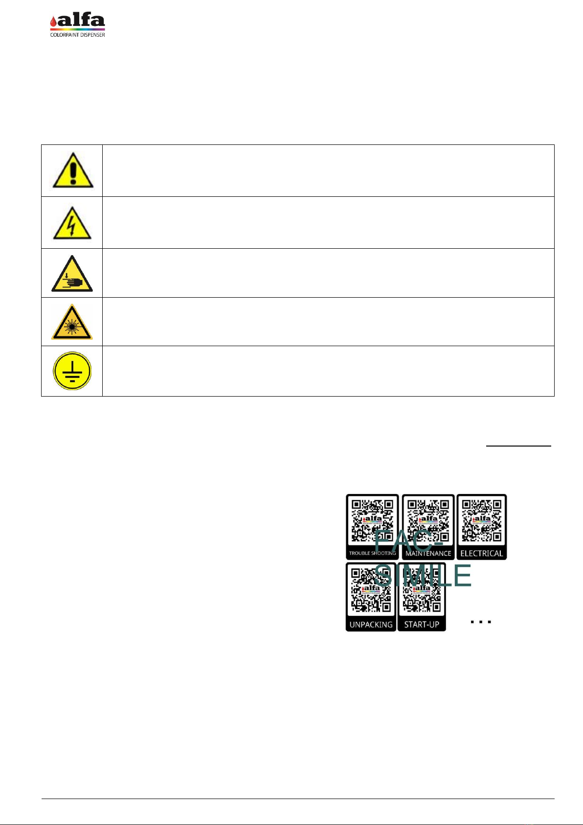
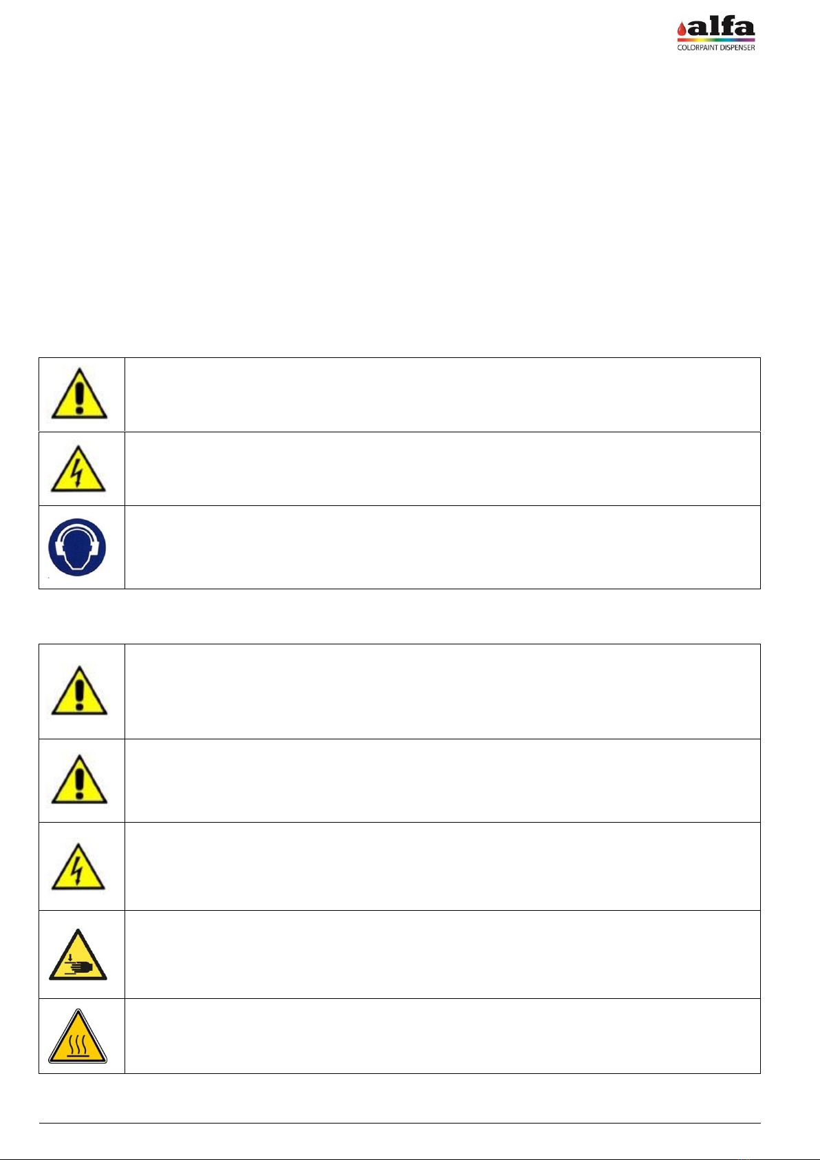
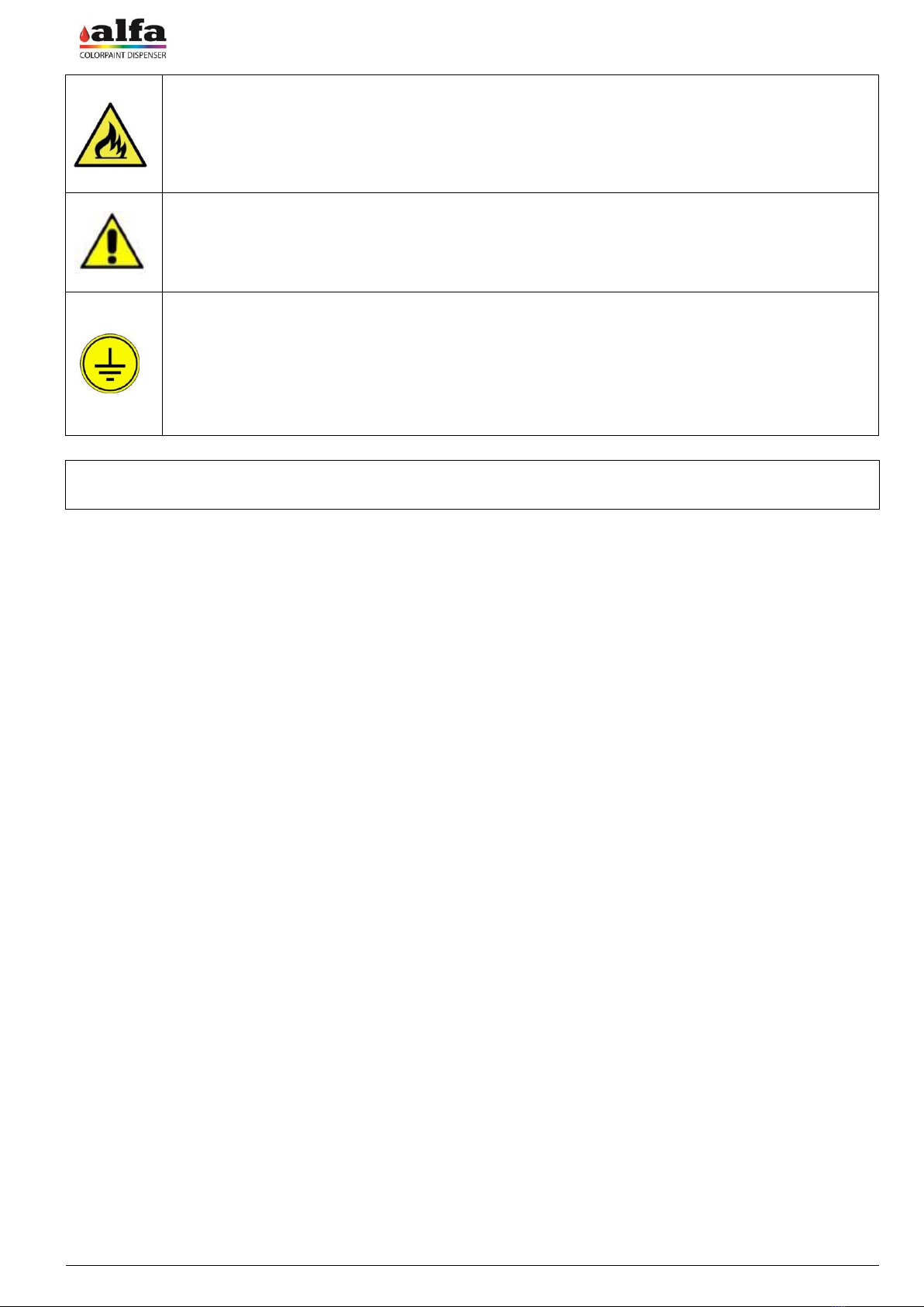
0.1.4. SYMBOLS USED IN THE MANUAL ...................................................................................................7
0.1.5. UPDATING THE MANUAL IN CASE OF MODIFICATIONS TO MACHINE.......................................7
0.1.6. OTHER INFORMATION SUPPORTS.................................................................................................7
0.2. INSTRUCTIONS FOR ORIGINAL SPARE PART AND CONSUMABLE ORDER....................................8
0.3. SAFETY INFORMATION...........................................................................................................................8
0.3.1. PRECAUTIONS AND USAGE REGULATIONS .................................................................................8
0.3.2. GENERAL SAFETY WARNINGS........................................................................................................8
0.3.3. USERS AND ACCESS LEVELS.........................................................................................................9
1. GENERAL INFORMATION............................................................................................................................10
1.1. INTRODUCTION .....................................................................................................................................10
1.1.1. MODELS AND VERSIONS...............................................................................................................10
1.1.2. COLORANT TURNING TABLE CONFIGURATIONS.......................................................................11
1.2. INTENDED AND UNINTENDED USE.....................................................................................................11
1.3. DESCRIPTION OF THE MACHINE ........................................................................................................11
1.3.1. MAIN COMPONENTS.......................................................................................................................11
1.3.2. COLORANT TURNING TABLE.........................................................................................................12
1.3.3. ACCESSING THE GROUPS.............................................................................................................12
1.3.4. LOADING AND UNLOADING ROLLER CONVEYORS....................................................................13
1.3.5. AUXILIARY FUNCTIONS..................................................................................................................13
1.3.6. LIFTERS............................................................................................................................................14
1.3.7. ELECTRICAL CONTROL PANEL.....................................................................................................14
1.3.8. CONTROL INTERFACE....................................................................................................................15
1.4. WORK CYCLE.........................................................................................................................................15
1.4.1. SWITCH-ON - RESET.......................................................................................................................15
1.4.2. OPERATOR INTERFACE AND MAINTENANCE INTERFACE .......................................................15
1.4.3. ALARMS............................................................................................................................................16
1.4.4. STAND-BY.........................................................................................................................................16
1.4.5. PRODUCT STIRRING AND RECIRCULATION ...............................................................................16
1.4.6. WORKING CYCLE............................................................................................................................17
1.5. TECHNICAL SPECIFICATIONS .............................................................................................................17
1.5.1. ELECTRICAL SPECIFICATIONS .....................................................................................................17
1.5.2. EQUIPMENT CLASSIFICATION AND REFERENCE STANDARDS ...............................................17
1.5.3. OPERATING CONDITIONS..............................................................................................................17
1.5.4. DIMENSIONS AND WEIGHTS .........................................................................................................18
1.5.5. PRODUCTION CAPABILITY AND TECHNICAL SPECIFICATIONS ...............................................18
1.5.6. CONSUMABLE STORAGE...............................................................................................................18
1.6. RESIDUAL RISKS AND DANGEROUS AREAS.....................................................................................19
1.6.1. CONTACT WITH PAINTS AND COMPONENTS .............................................................................20
1.6.2. GENERAL FIRST AID MEASURES..................................................................................................20
1.7. CERTIFICATIONS...................................................................................................................................21
1.7.1. END OF LIFE TREATMENT - WEEE DIRECTIVE ...........................................................................21
1.7.2. FCC ...................................................................................................................................................21
1.7.3. ROHS CHINA DECLARATION .........................................................................................................21
1.7.4. EC / UKCA DECLARATIONS............................................................................................................22
2. UNPACKING ..................................................................................................................................................24
2.1. GENERAL RECOMMENDATIONS.........................................................................................................24
2.1.1. DIMENSIONS OF THE PACKAGE...................................................................................................24
2.2. UNPACKING ...........................................................................................................................................25
2.3. OPENING PACKAGE AND CHECKING THE CONTENT......................................................................26
2.4. MOVING THE MACHINE (CR2 VERSION) ............................................................................................27
2.5. MOVING THE MACHINE (CR4 AND CR6 VERSIONS).........................................................................27

Operator Manual –CR6
EN
5
3. INSTALLATION .............................................................................................................................................28
3.1. CHOOSING THE ROOM.........................................................................................................................28
3.2. PRODUCT LABEL AND ELECTRICAL CONNECTION .........................................................................28
3.3. COMMISSIONING...................................................................................................................................29
3.3.1. PANEL DISASSEMBLY ....................................................................................................................29
3.3.2. REMOVING THE MECHANICAL AND PARKING RETAINERS ......................................................30
3.3.3. CARRIAGE EXTRACTION ...............................................................................................................31
3.3.4. ASSEMBLING THE SUPERVISOR PANEL .....................................................................................32
3.3.5. INPUT AND OUTPUT ROLLER CONVEYOR INSTALLATION .......................................................33
3.3.6. CANISTER OPENING.......................................................................................................................35
3.3.7. RESTORING ELECTRICAL CONNECTIONS BETWEEN MODULES ............................................35
3.3.8. FIELD WIRING CONNECTION.........................................................................................................35
3.3.9. PANEL REASSEMBLY .....................................................................................................................36
3.4. SWITCH-ON AND INITIALISATION .......................................................................................................36
3.5. SWITCH-OFF..........................................................................................................................................36
3.6. COMMISSIONING - PREPARATION .....................................................................................................37
3.6.1. PRODUCT LOADING........................................................................................................................37
3.6.2. CIRCUIT TRIGGERING AND RECIRCULATION.............................................................................38
3.6.3. SETUP OF CIRCUITS.......................................................................................................................38
3.7. ALFA40 SERVICE OVERVIEW ..............................................................................................................38
4. HOW TO PRODUCE A COLOUR..................................................................................................................41
4.1. MACHINE STATUSES............................................................................................................................41
4.2. PRODUCTION OF A COLOUR...............................................................................................................41
4.2.1. LOADING SHUTTLES ......................................................................................................................41
4.2.2. SELECTING FORMULA AND QUANTITY .......................................................................................41
4.2.3. LOADING THE SHUTTLE.................................................................................................................42
4.2.4. STARTING THE PRODUCTION PROCESS....................................................................................42
5. ORDINARY MAINTENANCE AND ADJUSTMENTS....................................................................................43
5.1. INTRODUCTION.....................................................................................................................................43
5.2. CANISTER TOPPING UP.......................................................................................................................43
5.3. RECORDING THE OPERATION............................................................................................................44
5.4. MINIMUM AND RESERVE LEVEL .........................................................................................................44
5.5. ADJUSTING MINIMUM LEVELS ............................................................................................................44
5.6. PRODUCT DISPOSAL............................................................................................................................44
6. ORDINARY MAINTENANCE AND CLEANING............................................................................................45
6.1. SCHEDULED MAINTENANCE...............................................................................................................45
6.2. SERVICE EQUIPMENT ..........................................................................................................................46
6.3. LUBRICATION ........................................................................................................................................47
6.4. ROLLER CONVEYOR CLEANING.........................................................................................................47
6.5. CLEANING GROUP MAINTENANCE.....................................................................................................47
6.6. PURGE....................................................................................................................................................47
6.7. MANUAL CONTROLS.............................................................................................................................48
6.8. EXTERNAL CLEANING..........................................................................................................................50
6.9. INTERNAL CLEANING ...........................................................................................................................50
6.10. COMPONENT SPILLING........................................................................................................................50
6.11. REPLACING THE FUSES.......................................................................................................................50
6.12. CHECK OF THE CORRECT OPERATION OF THE DOOR CONTROL SENSORS.............................51
7. EXTRAORDINARY MAINTENANCE.............................................................................................................52
8. TROUBLE SHOOTING..................................................................................................................................53

Operator Manual –CR6
6
FOREWORD
EN
0. FOREWORD
0.1. HOW TO USE THE MANUAL
0.1.1. IMPORTANCE OF THE MANUAL
The manual contains instructions and advice for the commissioning and use of the CR6 product.
Before installing and commissioning the system, carefully read this manual in all its parts and in particular the chapters
“GENERAL INFORMATION”, “INSTALLATION” and “HOW TO PRODUCE A COLOUR”, paying more attention to the
paragraphs related to precautions and safety alerts.
In case problems or difficulties should arise, the TECHNICAL SERVICE SUPPORT of Alfa Srl is always available to
provide the right support, advice, explanation and assistance.
Alfa Srl reserves the right to make modifications for improving its own products without prior notification.
The incorrect use of the system can lead to loss of warranty in all its forms and terms.
0.1.2. HOW TO KEEP THE MANUAL
Do not remove, modify, rewrite contents of this manual for any reason.
Keep the manual in a safe place, protected from heat and humidity.
0.1.3. HOW TO CONSULT THE MANUAL
This manual comprises:
•COVER PAGE IDENTIFYING THE TYPE OF PRODUCT
•TABLE OF CONTENTS
•INSTRUCTIONS AND/OR NOTES ON THE PRODUCT
The COVER PAGE identifies the product described in this manual.
Use the CONTENTS to find the list of CHAPTERS and PARAGRAPHS contained in the manual and their subjects.
The INSTRUCTIONS AND/OR NOTES ON THE PRODUCT define the safe working practices and advice on the
correct procedures and the skills required to correctly operate and maintain the system.
Some images of this manual having been enclosed for easier identification of the described parts may not be exactly
the same as the ones in your System.

Operator Manual –CR6
EN
FOREWORD
7
0.1.4. SYMBOLS USED IN THE MANUAL
The safety and advice symbols used in this manual are used to draw the reader’s attention to warnings concerning
safety or indicating good working practices.
The same symbols are also placed on the machine to indicate dangerous areas and refer to the relevant safety notes
in the manual.
MEANING OF THE SYMBOLS
WARNING! GENERAL DANGER
WARNING! HIGH VOLTAGE
WARNING! RISK OF CRUSHING.
WARNING! LASER RADIATION DANGER
GROUND CABLES
THIS SYMBOL INDICATES GROUND REFERENCE POINT.
0.1.5. UPDATING THE MANUAL IN CASE OF MODIFICATIONS TO MACHINE
If the MACHINE or MANUAL is MODIFIED in any way, an UPDATE could be sent for insertion into the printed Manual.
0.1.6. OTHER INFORMATION SUPPORTS
Several QR codes are present on the machine.
Each QR code allows accessing a web page containing
instructions and/or videos concerning the function shown
below the QR code.
Scan the barcode with an application suitable to open its
content.

Operator Manual –CR6
8
FOREWORD
EN
0.2. INSTRUCTIONS FOR ORIGINAL SPARE PART AND CONSUMABLE ORDER
To provide a fast and efficient service, always specify the following information when ordering replacement and
consumable parts:
−Machine type: as indicated on nameplate.
−Serial number: as indicated on nameplate.
−Quantity of each item required.
−Code of required part.
−Description of required part.
0.3. SAFETY INFORMATION
0.3.1. PRECAUTIONS AND USAGE REGULATIONS
The machine must be positioned in an enclosed area that complies with the environmental requirements set out in the
relevant paragraph.
Do not install the machine in a dusty environment.
Do not expose the machine to sources of heat, excessive cold, water, electromagnetic energy, or
sources of smoke.
The machine must be positioned on perfectly level flooring.
Always make sure that the power cable is intact and free of any cuts or cracks.
In case of cable damage, renew the cable using genuine spare parts.
The noise level generated by the machine is less than 70 DB (measured at a distance of 1 m and at a
height of 1.60 m from the floor).
This value can be exceeded in certain work environments.
If the noise to which the operator is exposed on a daily basis is presumably greater than 85 DB,
effective hearing protections must be used, as required by the 86/188/EEC regulations.
0.3.2. GENERAL SAFETY WARNINGS
CR6 is compliant with all the safety requirements of the main European and extra-European
Standards and Institutions. Despite that, it is suggested to read carefully the information contained in
this chapter and in the next pages since they show the possible dangerous situations and the
necessary precautions to take.
The machine is provided with doors and guards that prevent the operator from getting in contact with
mechanical and electrical hazardous parts.
A periodical check on the safety devices must be performed according to the instructions provided by
this manual.
If the safety protection systems are damaged, turn off the machine and call the technical service.
High voltage parts - Risk of electric shock
No high voltage part is accessible from the User area. All the high voltage circuits are contained into
enclosed areas and protected by fixed guards. The high-voltage internal parts are accessible to the
maintenance operator and are protected against direct contact with dangerous parts by means of IP
2X or higher class protection. Dangerous parts are marked by the symbol indicated on the side.
Dangerous mechanical parts - Risk of crushing or trapping.
Internal moving parts are accessible only to technical personnel. Do not put your hands into the
machine working areas. Tie hair to avoid the risk that it can be trapped in the machine.
For the same reason, keep away of the machine or avoid wearing any hanging objects such as ties,
necklaces, pendants or other similar items.
High-temperature parts - Risk of scalds
The machine includes no components or areas that may reach so high temperature as to become
dangerous for the user, the maintenance operator or the technician. The areas where this risk can
occur, under faulty conditions, are marked by the symbol indicated on the side.

Operator Manual –CR6
EN
FOREWORD
9
Flammable parts - Risk of fire
The machine is made from materials which do not propagate fire in order to minimise fire risk.
Nevertheless, the machine must be installed in a duly ventilated room, complying with the
manufacturer's installation requirements.
Never leave materials, fluid or foreign objects that might increase the risk and spread of a fire inside
the machine.
It is forbidden to modify the machine's internal an external protections. Contact Alfa's Technical
Support Service if necessary.
Alfa Srl shall bear no responsibility for any damage that may arise due to the failure to comply with the
above instructions.
In the event of a malfunction, contact the manufacturer's technical support service.
GROUND CONNECTION
Ground wire connection point.
Always ensure that yellow-green ground leads are duly fastened to the ground point indicated by the
symbol on the side.
DO NOT REMOVE GROUND CONNECTIONS.
In case of lead damage, switch machine off and immediately contact the technical service support.
IF THE EQUIPMENT HAS BEEN USED IN A MANNER NOT SPECIFIED BY THE MANUFACTURER, THE
PROTECTION PROVIDED BY THE EQUIPMENT MAY BE IMPAIRED
0.3.3. USERS AND ACCESS LEVELS
The machine has three different user interfaces:
−USER: an operator who uses the machine for the purpose of producing a colour sample;
−MAINTENANCE OPERATOR: user in charge of performing routine maintenance operations, such as canister
filling and autocap moisturising.
−TECHNICIAN: an expert operator authorised to access the machine's special diagnostic, calibration, configuration,
troubleshooting, and extraordinary maintenance functions.
In order to identify the various areas of intervention, the following definitions must be taken into account:
−USER AREA: the area outside the machine that the user accesses in order to produce a colour sample and to
perform ordinary maintenance operations;
−MAINTENANCE OPERATOR AREA: the area inside the machine, which can be accessed by opening the doors,
where ordinary maintenance operations are usually performed; extraordinary maintenance operations require the
access to the SERVICE AREA and are performed by the TECHNICIAN (replacement of dispensing units, circuits,
electric parts);
−SERVICE AREA (FOR USE BY TECHNICIANS): the internal areas of the machine that can not be accessed using
a single key, but with other tools (circuits electrical cabinets);

Operator Manual –CR6
10
GENERAL INFORMATION
EN
1. GENERAL INFORMATION
1.1. INTRODUCTION
The CR6 is a dispenser intended for the production of paint
for bodywork and CarRefinishing sectors, able to produce
both small quantities (e.g. 50ml) for touch-ups or colour
tests, and the quantities required to paint a complete car
(max. 1 litre per package).
The machine can be configured with a variable number of
circuits and canisters having different capacity, as
described in more detail below.
Each circuit can dispense a different product (products for
bodyworks).
Thanks to the accuracy and high resolution of the cutting-
edge dispensing systems designed and patented by Alfa,
the machine can reproduce any colour with exceptional
precision and absolute repeatability.
1.1.1. MODELS AND VERSIONS
This dispenser is available in three different configurations:
−CR6 (three modules, for a total of six product
dispensing heads and max. 96 total circuits);
−CR4 (two modules, for a total of four product
dispensing heads and max. 64 total circuits);
−CR2 (one module, for a total of two product dispensing
heads and max. 32 total circuits);
Each dispensing head consists of a rotary turning table
where up to 16 independent canisters can be housed.
Each dispensing head is equipped with one single
dispensing station.

Operator Manual –CR6
EN
GENERAL INFORMATION
11
1.1.2. COLORANT TURNING TABLE CONFIGURATIONS
Each turning table can contain a maximum of 16 products
and can be made up as follows:
•16 1.5 l canisters, or
•16 2.5 l canisters, or
•12 1.5 l canisters + 4 3 l canisters
Each circuit is equipped with its own 0.25 l/min pump
without actuator.
There is always only one actuator for each turning table.
1.2. INTENDED AND UNINTENDED USE
The machine is designed to dispense water-based liquid paint into a vessel having a known capacity.
Any uses other than those expressly described in this manual are strictly prohibited.
DO NOT USE PAINTS OR COLORANTS NOT APPROVED BY THE MANUFACTURER
DO NOT USE FLAMMABLE LIQUIDS
DO NOT USE CANS WITH CAPACITIES OTHER THAN THOSE PROVIDED (MAX 1 LITRE)
MAKE SURE THAT THE ELECTRICAL SPECIFICATIONS AND USAGE CONDITIONS FORESEEN BY THE
MANUFACTURER ARE MET PRIOR TO INSTALLATION (Para. 1.5).
1.3. DESCRIPTION OF THE MACHINE
The paragraph describes the main external and internal components of the machine and their function.
1.3.1. MAIN COMPONENTS
1. Colorant group cabinet
2. Colorant group cabinet (extractable)
3. Loading roller conveyor
4. Unloading roller conveyor
5. Lifters
6. Supervisor (User Interface touch screen)
7. Electrical control panels (on the back side)

Operator Manual –CR6
12
GENERAL INFORMATION
EN
1.3.2. COLORANT TURNING TABLE
Each dispensing head can house up to 16 product groups.
Circuits are placed on a turning table, which allows
dispensing from the various circuits sequentially.
Each product group can be equipped with one 1.5, 2.5 or 3
l canister and is provided with its own dispensing unit.
There is only one actuator allowing dispensing and is
exclusively coupled with the group opposite to dispensing
(in front of the operator). Therefore there is only one
dispensing station for each dispensing head, which is the
same where circuit recirculation can be executed.
1.3.3. ACCESSING THE GROUPS
The canisters of the groups housed in the upper part of the
machine can be accessed by opening the relevant upper
cover (1).
To open the cover, it is necessary to unlock the latch using
the key supplied.
The same key is required to unlock the lower carriages and
open them.
The groups in the lower part of the machine, instead, can
be accessed by extracting the relevant carriage (2).
The carriages are held in place by a locking system that
uses guides and a magnet.
When closing carriage and doors, pay attention to possible
risks of crushing.
Extract one carriage at a time: close the open carriage
before extracting the adjacent carriage.
By convention, numbering of the dispensing heads (1-6) is
that shown in the figure.
The software uses A..F references.

Operator Manual –CR6
EN
GENERAL INFORMATION
13
1.3.4. LOADING AND UNLOADING ROLLER CONVEYORS
On the left side of the machine there are can input (1) and
output (2) roller conveyors, as well as the output tunnel (3).
Cans can be transported in the machine only by using the
proper shuttles. The shuttle has to be chosen according to
the volume of the can you want to use and is defined
during machine configuration.
Manually load the shuttle containing the can on the loading
roller conveyor, then send the dispensing start command
on Alfa40 software (see chap.4 –“HOW TO PRODUCE A
COLOUR”).
The machine will load the shuttle through the motorised
roller conveyor and will perform a consistency check
between the selected volume and the volume of the can
actually loaded.
At the end of the process, the can will be positioned on the
output roller conveyor, where it can be manually removed.
1.3.5. AUXILIARY FUNCTIONS
In addition to the colorant turning table, each dispensing
head contains a cleaning station (1), a roller conveyor for
shuttle movement (2) and an electrical control panel (3)
that provides some service functions, as described in more
detail below.
The cleaning station is used to clean the dispensing nozzle
of each group from possible colorant residues, preventing
nozzle drying and clogging.
For each dispensing head, the following connections are
available:
4. IEC320 type C14 socket for the connection of a scale
(max. 100W*);
5. USB-A port for scale connection, through USB-RS232
converter (present only on dispensing head 1);
6. Main switch for dispensing head switching off and
IEC320 socket disconnection;
WARNING: dispensing head switch 1 switches off the
supervisor as well.
* AC connector - Warning –Connect only to one module
and at no more than 100W.

Operator Manual –CR6
14
GENERAL INFORMATION
EN
A heater (9) is present in the lower part of carriages. This
element is automatically activated when the temperature
drops below a programmable threshold, in order to keep
the product temperature above the minimum values
specified by the manufacturer.
1.3.6. LIFTERS
To move the shuttle from upper to lower heads and to the
unloading device, two lifters are used, positioned on the
left (1) and right (2) sides of the machine.
1.3.7. ELECTRICAL CONTROL PANEL
It is located on the side of the machine and houses the main electrical connections of the system.
1. On/off Switch
2. “192.168.0.100”: RJ45 socket for direct
communication with the machine supervisor
(address 192.168.0.100:8080/admin)
3. “192.168.1. ”: RJ45 socket for local Ethernet
network connection (product dispensing heads)
In the centre there is the opening for the field wiring
connection.
WARNING: After the machine switching off, wait at least 2 minutes before switching it on again (it is necessary to wait
the internal controller shut down).

Operator Manual –CR6
EN
GENERAL INFORMATION
15
1.3.8. CONTROL INTERFACE
The machine is equipped with a touch display used as
User Interface for the operator, on which the machine
supervisor software runs.
For details on the functions of the machine supervisor
software, refer to chap.4.
1.4. WORK CYCLE
Following are the possible machine statuses:
STANDBY: machine ready, waiting for controls
DISPENSING: dispensing in progress
RESET: reset in progress
ALARM: machine error
DIAGNOSTIC: machine waiting for direct controls
ROTATING: colorant circuit positioning (only for refill operations)
JAR POSITIONING: movement of roller conveyors and lifters
For further details, refer to the next part of this paragraph and to chapter 4.
1.4.1. SWITCH-ON - RESET
Upon switch-on, system runs a reset routine and sets to stand-by, thereby allowing the operator to use the Software
control interface and set production of one or several colour samples.
1.4.2. OPERATOR INTERFACE AND MAINTENANCE INTERFACE
The machine use and maintenance are managed by means of web interfaces. Refer to chapter 3 –INSTALLATION –
for the machine initialisation operations and to chapter 4 –HOW TO PRODUCE A COLOUR - for a description of the
basic functions. For a description of the low level functions, refer to the "software manual".

Operator Manual –CR6
16
GENERAL INFORMATION
EN
1.4.3. ALARMS
The interface installed on the machine, which can be viewed using a Web Browser (e.g. Google Chrome), shows in
real time any critical machine alarms requiring immediate operator intervention and preventing the use of the machine,
as well as non-critical alarms, reminding the operator of (even not immediately) required service operation(s).
Critical alarms include:
−Communication errors
−Motor movement errors (e.g. loss of steps)
−Error on can detection
−Timeout error in roller conveyor transfer
−Errors for open doors or carriages
Non-critical alarms include:
−Colorant quantity below the warning level
−Colorant quantity below the minimum level*
*: this alarm does not prevent the use of the machine unless a formula is set that requires a colorant volume higher
than the available one (see paragraph 5 for further details).
1.4.4. STAND-BY
When the machine is not in use, it performs some activities required for a trouble-free operation. These activities
include:
•Component stirring;
•Component recirculation;
1.4.5. PRODUCT STIRRING AND RECIRCULATION
The product stirring and recirculation functions are carried out cyclically on all circuits, at regular intervals that can be
programmed via software.
Colorant circuits are all simultaneously stirred at any rotation of the turning table on which the groups are installed.
The default values of the duration and pause variables of each function are indicated in the following table:
Stirring
Recirculation
Components
At any turning table rotation and
before any colorant recirculation
1’ every 30’
The parameters can be set independently for each circuit of the machine by accessing the ADMIN interface (see chap.
4 - ACCESS TO THE CONFIGURATION ADVANCED FUNCTIONS and the “software manual”).
Upon commissioning, the installing TECHNICIAN must adjust stirring and recirculation parameters depending on the
recommended settings for every installed product. Access to programmable functions is described in the “Software
manual”.
Stirring speed is approx. 15 rpm and can not be modified.

Operator Manual –CR6
EN
GENERAL INFORMATION
17
1.4.6. WORKING CYCLE
When the colour production input is sent, the machine performs the following work phases:
1. CAN LOADING ON SHUTTLE
2. BARCODE READING AND CONSISTENCY CHECK BETWEEN CAN CAPACITY AND VOLUME TO BE
DISPENSED
3. COMPONENT DISPENSING (WITH CIRCUIT POSITIONING)
4. SHUTTLE TRANSFER TO THE NEXT HEAD AND REPETITION OF POINT 3 IF FORESEEN
5. SHUTTLE LOAD IN THE DOWNSTROKE LIFTER AND TRANSFER TO THE LOWER HEADS
6. DISPENSING AND TRANSFERS TO THE NEXT HEADS UP TO THE SHUTTLE UNLOADING IN THE
UPSTROKE LIFTER
7. UNLOADING ROLLER CONVEYOR EJECTION (WITH “FULL UNLOADING” CONTROL)
8. RETURN TO STANDBY
The machine is able to manage several shuttles at the same time, with up to 6 cans in the six dispensing stations in
one production cycle.
1.5. TECHNICAL SPECIFICATIONS
1.5.1. ELECTRICAL SPECIFICATIONS
MODEL
CR6
CR4
CR2
Power supply
120-240Vac ±10% 50/60Hz
Max current (A)
10.0-5.2
7.0-3.2
3.2-2.1
Max. absorbed power* (W)
1200
900
400
Fuses 5X20 mm (2pcs internal)
T10A-250V
T8A-250V
T4A-250V
(*) includes 1 AUX 100W output.
1.5.2. EQUIPMENT CLASSIFICATION AND REFERENCE STANDARDS
Overvoltage category
II
See note (1)
Protection classification
IP 20
Class of equipment
I
Reference standards
IEC 61010-1
IEC EN 61326-1
UL1450
Airborne noise (2)
Lower than 70 dB (A)
Note (1): The equipment is protected for overvoltage up to 1500V. For power lines subjected to transients with peaks
of voltage greater than 1500V, the use of external suitable protection devices is recommended.
Note (2): A-weighted sound pressure level determined during normal use at a distance of 1 m from the surface of the
machinery and at a height of 1.60 m from the floor.
1.5.3. OPERATING CONDITIONS
Operating temperature (*)
+5 ÷ +35°C
Relative humidity
30% ÷ 90% without condensate
Storage temperature
-25 ÷ +55°C
Altitude
2000 m
(*) The components lose their rheological characteristics outside the temperature range recommended by the
manufacturer. Comply with the specifications of the components used.

Operator Manual –CR6
18
GENERAL INFORMATION
EN
1.5.4. DIMENSIONS AND WEIGHTS
MODEL
CR2
CR4
CR6
Height (mm)
1620
1620
1620
Width (mm)
1980
2780
3580
Depth (mm)
880
880
880
Unladen weight (kg)
315
565
815
The unladen weight of every single module, without lifters and without input and output roller conveyors, is approx.
250kg, while the laden weight of each module can exceed 300kg (variable value depending on the circuit configuration
and the type of products loaded).
1.5.5. PRODUCTION CAPABILITY AND TECHNICAL SPECIFICATIONS
Net colour sample capacity
50ml to 1l
Canister capacity
1.5, 2.5, 3 litres
Max number of circuits
32 to 96 (according to configuration)
Types of products that can be
used
Products for CarRefinishing
Colours that can be dispensed
Infinite
Circuit Capacity/Flow rate
(sequential dispensing)
0.25 litres/min
Minimum quantity that can be
dispensed
1/1920 fl oz (0.0154 cc)
Product strainer
0.9 mm
Dispensing mode
Sequential on each dispensing head
Output*
100cc in 35 seconds
*Output depends on type of formula and software setup
1.5.6. CONSUMABLE STORAGE
Products
Refer to manufacturer's instructions

Operator Manual –CR6
EN
GENERAL INFORMATION
19
1.6. RESIDUAL RISKS AND DANGEROUS AREAS
USER AND MAINTENANCE OPERATOR
The potentially dangerous areas associated with mechanical moving parts:
−Colorant turning table movement: the support base
rotation during dispensing or refill operations does not
present any risk that is not obvious; however, it is
advisable to be careful and not to approach the parts
with hands, arms, hair or clothes during operation.
−Circuit canisters: risk of squeezing arms, hands or
fingers due to the movement of stirring blade in case of
failure or malfunction of door opening sensors. Stirring
start is timed by the software and is sudden (excluding
when the machine is in diagnostics or refill mode). Do
not insert your hands into the canisters. Always shut
off the machine prior to performing any necessary
interventions.
−Lower carriage extraction: be careful when refitting the
carriage. Possible risk of squeezing hands and fingers
between the fixed and the mobile parts (figures on the
side)
TECHNICIAN: The authorised technician can remove the machine fixed protections and access the internal parts
containing live electrical components.
−Electrical panel area: risk of electric shock.
Any intervention that requires the operator to access zones where risks of electric shock are present must be
performed with the machine off.
REMOTE ASSISTANCE: The machine may also be remotely activated via Personal Computer or
Smart device. Pay maximum attention during access to dangerous areas.

Operator Manual –CR6
20
GENERAL INFORMATION
EN
1.6.1. CONTACT WITH PAINTS AND COMPONENTS
Always beware of any product leaks from the machine or circuits during production, as well as during cleaning and
maintenance operations.
Contact with the components (coloured bases) can cause irritations or injuries if not properly treated.
In case of need always refer to the safety sheet of the concerned liquid, available at the colorant manufacturer.
1.6.2. GENERAL FIRST AID MEASURES
In the event of eye contact: remove contact lenses, if present. Immediately rinse the eyes with running water for at
least 15 minutes, holding the eyelids open. Consult a physician immediately.
In the case of skin contact: remove the contaminated garments. Wash the skin thoroughly with soap and water.
Ingestion: immediately consult a physician and show them the can, label or material safety data sheet. Keep the
person warm and relaxed. Do not induce vomiting.
Other manuals for CR6
2
Table of contents
Other Alfa Network Industrial Equipment manuals
Popular Industrial Equipment manuals by other brands

FOREDOM
FOREDOM Handpiece H.20 Important instructions

CASSENS & PLATH
CASSENS & PLATH Reflecta/5 Operation & installation

ABB
ABB MirEvo Twinspot TW500 230V Instruction leaflet

Festo
Festo Silencer-Set UOMS Series Assembly instructions

Seifert
Seifert 752501B001 user manual

TCi
TCi HarmonicGuard HGP Installation, operation and maintenance manual

American Eagle
American Eagle FuelMate owner's manual

ABB
ABB HT614598 Operation manual

AWG
AWG S2 Original operating manual

Emerson
Emerson HART CAM216 Instruction and operation manual

Infinite
Infinite TRANSTECTOR CCTV-PTZ Series installation instructions

Siemens
Siemens 3VA960 0QB00 Series operating instructions