Alfa Network LU-VE Optigo FMS25 User manual

31592031EN-01
2
Alfa LU-VE is a trademark registered and owned by LU-VE Group.
Alfa LU-VE reserves the right to change specifications without prior notification.
Index
1. Important information ............................................................................................................ 3
1.1 Disclaimer ................................................................................................................................. 3
1.2 Intended use ............................................................................................................................. 3
1.3 Where to nd product information ............................................................................................ 3
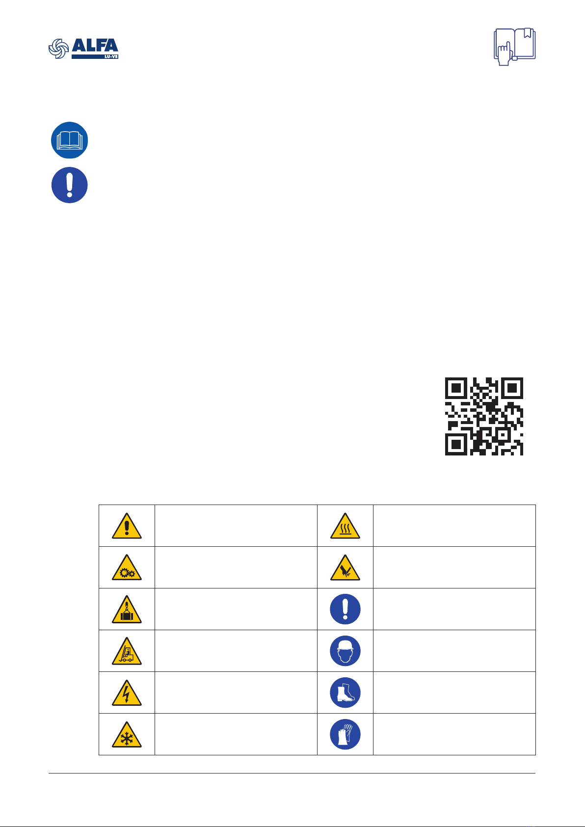
1.4 Warning symbols ...................................................................................................................... 3
1.5 Health, safety and hygiene ....................................................................................................... 4
1.6 Checks at delivery .................................................................................................................... 4
1.7 Return of unused heat exchangers .......................................................................................... 4
1.8 Guarantee ................................................................................................................................ 4
1.9 Disposal .................................................................................................................................... 4
2. Product description ............................................................................................................... 5
2.1 General information and application ......................................................................................... 5
2.2 Standard conguration ............................................................................................................. 5
2.3 Optional features ...................................................................................................................... 5
2.4 Code description ...................................................................................................................... 6
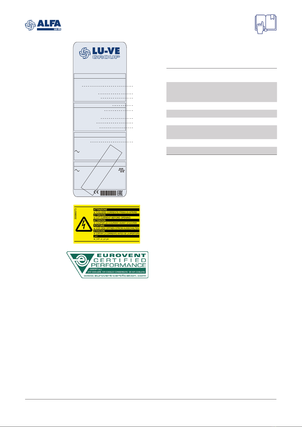
3. Product labels ......................................................................................................................... 6
4. Transport and storage ........................................................................................................... 8
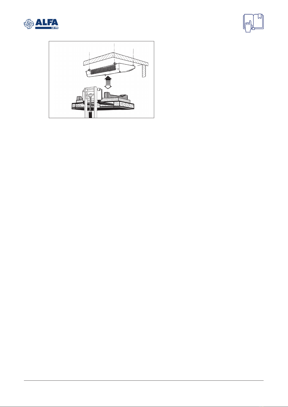
5. Unpacking and lifting ............................................................................................................. 8
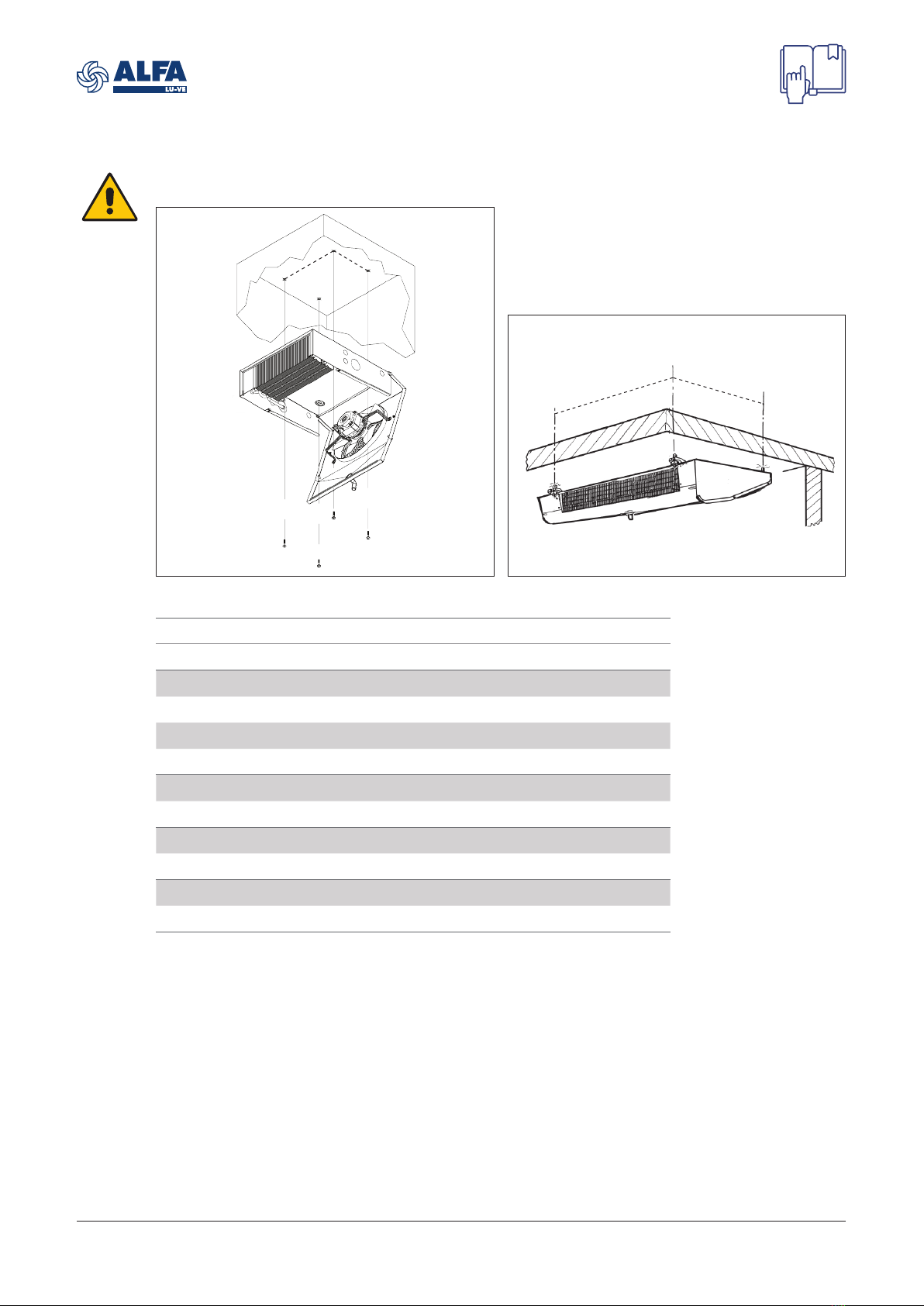
6. Installation ............................................................................................................................ 10
6.1 Mounting dimensions ............................................................................................................. 10
6.2 Mounting bracket .................................................................................................................... 11
6.3 Technical spaces .................................................................................................................... 11
6.4 Refrigerant connections ......................................................................................................... 12
6.5 Pressure test .......................................................................................................................... 13
6.6 Drain line ................................................................................................................................ 13
6.7 Electrical connections ............................................................................................................. 14
6.8 Power failure .......................................................................................................................... 14
6.9 Fan motors connections ......................................................................................................... 15
6.10 Defrost .................................................................................................................................... 16
6.11 Electric defrost (E) .................................................................................................................. 16
6.12 Driptray heater (HD) ............................................................................................................... 18
7. Maintenance .......................................................................................................................... 19
7.1 Shut down periods .................................................................................................................. 19
7.2 Moisture in the refrigeration system ....................................................................................... 19
7.3 Cleaning and disinfecting ....................................................................................................... 19
7.4 Casing .................................................................................................................................... 19
7.5 Coil and drip tray .................................................................................................................... 19
7.6 Electric defrost elements replacement ................................................................................... 20
7.7 Fans ....................................................................................................................................... 21
7.8 Fan replacement .................................................................................................................... 21
8. Residual risks ....................................................................................................................... 22
9. Troubleshooting ................................................................................................................... 22
10. Spare parts ............................................................................................................................ 23

31592031EN-01
3
Alfa LU-VE is a trademark registered and owned by LU-VE Group.
Alfa LU-VE reserves the right to change specifications without prior notification.
1 Important information
1.1 Disclaimer
This Instruction Manual applies to all Optigo FMS air cooler products. Manual must be carefully
examined and instructions should be followed up at all times.
Alfa LU-VE does not accept liability for any damage resulting from non-compliance to the
instructions as given in the manuals and order-related documents.
1.2 Intended use
Air coolers are partly completed machinery according to Machine Directive 2006/42/EC and are
intended for incorporation in cooling systems. Declarations of Incorporation are available on
alfa.luvegroup.com. The product is built according to the following standards:
• PED 2014/68/EU
• Safety of Machinery EN 60204-1
• Directive 2014/30/EC and subsequent modifications. Electromagnetic compatibility.
• Low Voltage - Reference Directive 2014/35/EC
However it is forbidden to operate our equipment before the machine incorporating the products or
making part thereof has been declared to be in conformity with the EC Machine Directive.
1.3 Where to find product information
Detailed technical data for individual product models are available in order related documents,
on the product label and in product data sheets. Comprehensive technical information for all Alfa
LU-VE air heat exchanger products is available on-line on alfa.luvegroup.com. This includes:
• Product manuals
• Instruction manuals
• Product leaflets & brochures
• Product data sheets (selection software)
• Dimensional drawings
• Certificates
Alfa LU-VE offers world-wide service and support. In case of any questions
or uncertainty please contact your local Alfa LU-VE representative.
Contact addresses are available at alfa.luvegroup.com.
1.4 Warning symbols
The following warning symbols are used in Alfa LU-VE instruction manuals.
General warning.
Risk of malfunctioning and/or
damage.
Hot surfaces. Danger of burns.
Wear adequate protection.
Moving parts. Danger of injuries.
Do not operate without protection guard mounted.
Sharp surface. Danger of cutting injuries. Wear
adequate protection.
Overhead load.
Never stand or walk below the load.
Mandatory prescription.
Follow instructions as provided.
Forklift trucks or other logistic vehicles.
Stay clear of working space.
Risk of injuries.
Wear head protection.
Electrically powered component. Switch off power
supply before any maintenance or installation
activity.
Risk of injuries.
Wear safety footwear.
Cold parts. Danger of frostbite injuries.
Wear adequate protection.
Risk of injuries.
Wear protective gloves.
alfa.luvegroup.com/fms

31592031EN-01
4
Alfa LU-VE is a trademark registered and owned by LU-VE Group.
Alfa LU-VE reserves the right to change specifications without prior notification.
1.5 Health, safety and hygiene
Ensure that the following guidelines are observed:
• All work on the equipment must be carried out by trained personnel.
• The electrical supply is suitable for the equipment supplied.
• Refrigerant, temperature and pressure must agree with the data on the product label of the
relevant heat exchanger.
• As the heat exchanger is supplied indirectly, the producer is not acquainted with its actual
application.
• The heat exchanger should be installed in conformance with the recognized national standards
of electrical and refrigeration installation practice.
• The supplied heat exchanger is optimized for the refrigerants as stated in the data sheet or
order documents. Please contact Alfa LU-VE before using any other refrigerants. The allowed
maximum pressure is noted on the type plate. During production the heat exchanger was
subjected to a strength test exceeding the design pressure. However, during normal use the
design pressure may not be exceeded.
• Heat exchangers supplied by Alfa LU-VE are normally not equipped with a high-pressure cut
out. The installer is responsible for fitting a high-pressure cut out on the system in which the
heat exchanger is used.
• The heat exchanger shall not be blocked in. If the ambient temperature rises, the pressure could
rise and exceed the design pressure.
• It is not permitted to use the heat exchanger for any purpose other than the one it was designed
for by Alfa LU-VE.
• If the equipment is used in the food industry, responsibility with regard to hygienic conditions lies
with the end user.
1.6 Checks at delivery
At the moment of delivery, carefully check the units.
All finned coils are pressure tested with dry air, sealed and supplied with a slight overpressure. Prior
to installation, the leak resistance must be checked with the schrader valve.
Any present damage must be reported on the delivery note with a description of the damage.
Damaged heat exchangers, including when the damage is not externally visible, are to be reported
to the shipping agent and Alfa LU-VE within 24 hours.
1.7 Return of unused heat exchangers
Air heat exchangers that have been delivered in accordance with orders are in principle not
returnable. Heat exchangers can only be returned under certain conditions and following
consultation with Alfa LU-VE. This applies exclusively to unused units. The heat exchangers that
are to be returned should be delivered carriage paid to Alfa LU-VE in the original, undamaged and
unwritten factory packaging. Not returnable are:
• Heat exchangers older than three months from the invoice date.
• Heat exchangers that have already been built in and/or are damaged.
1.8 Guarantee
For our guarantee conditions, we refer to the Terms of Delivery. In general, the warranty period
between Alfa LU-VE and the customer is 24 months from factory invoice date or 12 months of
operation, which ever comes first. Heat exchangers must not be returned or disposed of, other
than in accordance with instructions from Alfa LU-VE. Contact your local Alfa LU-VE representative
before any remedial action is taken on the units, otherwise warranty may be void.
1.9 Disposal
After decommissioning the heat exchanger coil should be emptied from refrigerant fluids. Avoid
any emissions in the environment. Any refrigerants and oil residuals must be properly disposed of
according to applicable environmental regulations. The fully emptied heat exchanger unit, including
all electrical components, should be handed in to the proper authorized companies for recycling.

31592031EN-01
5
Alfa LU-VE is a trademark registered and owned by LU-VE Group.
Alfa LU-VE reserves the right to change specifications without prior notification.
2 Product description
2.1 General information and application
Optigo FMS is a commercial slim air coolers line for general application in small to medium-sized
cooling and freezing rooms. All FMS models are characterised by a low silhouette for the efficient
use of cold room space.
• Refrigerants: HFC (FMSE) and CO2(FMSX)
• FMS25 capacity range (SC2 with R404): 760 up to 880 W
• FMS30 capacity range (SC2 with R404):1900 up to 7450 W
• FMS25 air quantity: 460 up to 510 m³/h
• FMS30 air quantity: 1200 up to 4800 m³/h
Model Refrigerant Max working pressure
FMSE HFC* 24 bar
FMSX CO260 bar
* Fluid group 2 according to EN 378
2.2 Standard configuration
• High efficiency coil manufactured from internally grooved Cu tubes and aluminium fins.
• Optigo FMS coolers are available with 1 to 4 fans. Fitted with AC/EC fan motors available in two
diameters (254 and 300 mm). Power supply 230/50-60/1.
• Durable aluminium alloy metallic casing. Hinged driptray. Dismountable and openable casing for
cleaning purposes.
• Plastic drain connection.
• Fan motors wired to connection box.
• Fitted with schräder valve on the suction connection for testing purposes. Each heat exchanger
is leak tested with dry air and finally supplied with a dry air pre-charge.
2.3 Optional features
• Electric defrost in coil (E)
For cold rooms with room temperatures below 4 °C frost build-up is likely, the application of a
defrosting system is recommended. The stainless steel defrost elements are connected to
dedicated terminal box.
• Driptray heater (HD)
• Coil protection: pre-coated aluminium fins (AP)

31592031EN-01
6
Alfa LU-VE is a trademark registered and owned by LU-VE Group.
Alfa LU-VE reserves the right to change specifications without prior notification.
2.4 Code description
FMS 25 E A - 1 4 - 4 N - AL BO
1 2 3 4 5 6 7 8 9 10
1 Optigo FMS slim commercial air cooler
2 Fan diameter (25=254 mm, 30=300 mm)
3 Refrigerant system (E=HFC, X=CO2)
4 Fan motor type (A=AC, E=EC)
5 Number of fans (1 to 4)
6 Coil type (1, 2, 3, 4)
7 Fin spacing (4=4.5 mm, 6=6.0 mm, 7.0 mm)
8 Defrost system (N=air defrost, E=electric defrost in coil, HD=driptray heater, E+HD=electric
defrost in coil+driptray heater)
9 Fin material (AL=aluminium, AP=pre-painted aluminium)
10 Packing (BO=box, BP=box + pallet, CR=crate)
3 Product labels
Manufacturedby
SEST-LUVE-POLSKAsp. z. o. o.
ul.Wyczólkowskiego 30,
44-109Gliwice, Poland
HEATEXCHANGER
FMS
CODE:
S/N:
PEDCAT ART 4.3
Fluid:
VOLUME:
Ts:
MaxPres:
VENTILATION
Nr
.Motors:
Power:
N°
N°
MADEIN
POLAND
DEFROSTING
Manufacturedby
SEST-LUVE-POLSKAsp. z. o. o.
ul.Wyczólkowskiego 30,
44-109Gliwice, Poland
HEATEXCHANGER
FMS
CODE:
S/N:
PEDCAT ART 4.3
Fluid:
VOLUME:
Ts
:
MaxPres:
VENTILATION
Nr
.Motors:
Power:
N°
N°
MADEIN
POLAND
DEFROSTING
Manufacturedby
SEST-LUVE-POLSKAsp. z. o. o.
ul.Wyczólkowskiego 30,
44-109Gliwice, Poland
HEATEXCHANGER
FMS
CODE:
S/N:
PEDCAT ART 4.3
Fluid:
VOLUME:
Ts:
MaxPres:
VENTILATION
Nr.Motors:
Power:
N°
N°
MADEIN
POLAND
DEFROSTING
①
②
②
①
on the electrical
connnections side
FMS25
FMS30

31592031EN-01
7
Alfa LU-VE is a trademark registered and owned by LU-VE Group.
Alfa LU-VE reserves the right to change specifications without prior notification.
Manufactured by
SEST-LUVE-POLSKA sp. z. o. o.
ul. Wyczólkowskiego 30,
44-109 Gliwice, Poland
HEAT EXCHANGER
FMS
CODE: 10220733
S/N: 6449383/2020
PED CAT ART 4.3
Fluid: FLUID GROUP 2
VOLUME: 1.10
dm3
Ts:
-40 °C +55 °C
Max Pres: 2.4 MPa
VENTILATION
Nr. Motors: 1
PowerS: 230 V 50 Hz
85 W 0.73 A
N°
N°
MADE IN
POLAND
DEFROSTING
EXAMPLE
EXAMPLE
1. Product label
This label is positioned inside the casing.
Model Refer to paragraph "2.4
Code description"
Product code
Product Serial nr.
Communicate these when
ordering spare parts as
they identify the unit
PED Category According to PED
Fluid Refrigerant
Volume Coil Volume
Ts Range of operating
temperatures for the coil
Max Pres Max working pressure
Nr Motors Number of fans
Product code
Product serial nr.
Fluid
Volume
Ts
Max Pres
Nr. Motors
PED category
Model
2. Electrical warning
Electrically powered component. Switch off
power supply before any maintenance or
installation activity.
Eurovent
Sticker is applied when the product is included
in the Eurovent Certify All program.

31592031EN-01
8
Alfa LU-VE is a trademark registered and owned by LU-VE Group.
Alfa LU-VE reserves the right to change specifications without prior notification.
4 Transport and storage
During transportation the heat exchanger must be handled with all required care. Any instruction or
warning signs attached to the heat exchanger or the packaging must be followed. Avoid shocks or
continuous vibrations during transport. These may cause damage to the product. If required, consult
Alfa LU-VE and disassemble during transport any parts that are likely to be set into vibration. Air
heat exchangers must be adequately fixed on the transport vehicle. If temporary storage of the heat
exchanger is required, the following points should be observed:
• Store the heat exchanger in its packing, in a dry place with sufficient protection against sun and
other environmental influences.
• Always place air heat exchangers on an even surface.
• Do not stack air heat exchangers unless explicitly indicated this is allowed.
• Storage temperature between -40 °C and +50 °C.
• Never open or remove the schrader valves. Overpressure in the coil must be maintained.
Shelf life of air coolers is one year. If longer storage periods occur, check:
• Proper functioning of the fan motor.
• Mounting brackets, lifting lugs and fan fixings for corrosion.
Optigo FMS air coolers are delivered in a reinforced cardboard box. Handling and positioning can
take place manually. When more units are delivered in a single shipment, packed air coolers may
be stacked during transportation.
5 Unpacking and lifting
Remove the packing and take out cooler unit. Remove the transparent protection film from metallic
parts, if present.
FMS25 FMS30
max 5
max 2
Respect the maximum number of stacked air
cooler units.

31592031EN-01
9
Alfa LU-VE is a trademark registered and owned by LU-VE Group.
Alfa LU-VE reserves the right to change specifications without prior notification.
Ensure that the cooler is not lifted directly onto
the driptray or the finned coil. Utilizing the proper
wooden transport beams and/or pallets prevents
the cooler bending at the extremes such that
the cooling circuit or other components are
damaged.
Lift the unit to mounting position and secure
following instructions given in chapter "6
Installation". After having secured the cooler,
the forks may be lowered and the remaining
packaging materials can be removed.

31592031EN-01
10
Alfa LU-VE is a trademark registered and owned by LU-VE Group.
Alfa LU-VE reserves the right to change specifications without prior notification.
6 Installation
6.1 Mounting dimensions
Coolers must be hung such that the coolers can contract and expand somewhat. Cooler contraction
occurs during refrigeration operation, and cooler expansion occurs during defrost. For air coolers
with copper tubing this figure runs up to 1.65 mm per meter cooler length. All heat exchangers must
be set up level. Weight information are listed on the product label and/or in the relevant product
documentation.
FMS25
A
190
FMS30
A
716
Model No. fans Coil type A (mm)
FMS25 1 4 470
FMS30 1 1 593
FMS30 1 2 593
FMS30 1 3 938
FMS30 1 4 938
FMS30 2 1 1148
FMS30 2 2 1148
FMS30 3 1 1703
FMS30 3 2 1703
FMS30 4 1 2258
FMS30 4 2 2258
For FMS25 the driptray must be opened to
access the fixing points.

31592031EN-01
11
Alfa LU-VE is a trademark registered and owned by LU-VE Group.
Alfa LU-VE reserves the right to change specifications without prior notification.
6.2 Mounting bracket
Use suitable studs when mounting the unit to the
ceiling.
Fix the unit to cold room ceiling by securely
tightening nuts and washers.
FMS25: Ø 6 mm
FMS30: Ø 8 mm
6.3 Technical spaces
Heat exchangers should be positioned such that the following criteria are met:
• Adequate space must be left on the air inlet side of the heat exchanger. The air discharge side
should be free of restrictions. Recirculation of air is to be avoided.
• The heat exchangers should not be connected to ducting on either the air inlet side or discharge
side, unless the heat exchanger has been specifically designed for such an application.
It is important to remember that the total amount of heat to be dissipated depends on receiving
the full design air volume at the design entry air temperature which allows this air to be freely
discharged after passing through the heat exchanger. Any restrictions may impair the performance
of the cooler. If in doubt, please check with Alfa LU-VE.
120 mm
100 mm
FMS25 FMS30

31592031EN-01
12
Alfa LU-VE is a trademark registered and owned by LU-VE Group.
Alfa LU-VE reserves the right to change specifications without prior notification.
IN
OUT
NO - NO - NON -NEIN - NO - HET SI - YES - OUI - JA - SI - ДА
6.4 Refrigerant connections
Do not adapt headers position to the suction line.
All pipework and connections must be made in accordance with good refrigeration design and
installation practice. Ensure that no stresses are transmitted to the pipework. All pipework should be
adequately attached to the walls/ceilings of the cold room and not only to the cooler itself. Pipework
must be adequately supported to prevent vibration or external load on the cooler headers, etc.
Ensure the supply circuit is closed (no pressure)
before connecting the suction lines.
Ensure the flame nozzle is not aimed at the
equipment, when welding. Insert a protection
shield if required.

31592031EN-01
13
Alfa LU-VE is a trademark registered and owned by LU-VE Group.
Alfa LU-VE reserves the right to change specifications without prior notification.
TeTs1 Trs
Ts1=cold room air inlet temperature.
Te=evaporating temperature. It is related to the
refrigerant pressure on the unit cooler outlet.
Trs=refrigerant superheat temperature, on
suction line near thermostatic valve bulb.
(Trs-Te)=superheat
(Trs-Te) ≤ 0.7 x (Ts1-Te)
Keep the superheat as low as possible to obtain
maximum unit cooler performance.
The thermostatic valve fitted must be correctly
sized for the installation conditions and adjusted
for correct system operation.
6.5 Pressure test
6.6 Drain line
Check all drain lines and driptrays to ensure that no improper material such as, e.g., packaging
material blocks the drain.
In FMS25 models, mount PVC driptray drain.
Tighten by hand only. Close the driptray.
60°
For all models, connect the drain tubing to the
drain connection.
The drain line diameter must be at least the size
of the driptray drain diameter and should be laid
with an adequate slope. For room temperatures
below 0 °C drain line insulation and defrosting
are required.
A syphon must be installed on the drain line,
outside the cold room.
Tighten drain connection by hand only.

31592031EN-01
14
Alfa LU-VE is a trademark registered and owned by LU-VE Group.
Alfa LU-VE reserves the right to change specifications without prior notification.
6.7 Electrical connections
All electrical connections must be made in accordance with the locally valid regulations and in
conformance with good installation practice. The site supply voltage, frequency, accepted power
rating and number of phases must comply with the details on the technical documentation. All
electrical supply lines must be connected to the terminal boxes through suitable waterproof glands
using bottom entry or, in case of horizontal installation, the cable is routed to form a water trap.
If the heat exchangers are installed and there is to be an appreciable delay in putting the plant into
operation, a temporary electrical supply should be connected to each motor, sufficient to run for
at least 4 hours. This procedure should be carried out at least once every 4 weeks, until the heat
exchanger is fully operational. It is up to the end user to verify the conditions for protection by
automatic disconnection of supply, according to applicable standards. Heat exchangers are
designed for TN power systems. The insulation fault protection must be part of power supply of the
heat exchanger and is not supplied by the manufacturer.
The following data determine which connection diagram is to be selected and respected for
electrical installation:
• Heat exchanger model indication
• Fan motor type
• Electrical options
When in doubt always contact your local supplier or Alfa LU-VE representative for assistance.
Ensure complete electrical isolation before performing any wiring.
Q
U
P
M motors
heaters
Remove the terminal block cover (P).
Insert the cables into the grommet (U) and
block them with their respective gland. Connect
terminals by following the wiring diagrams on the
cover. When all connections are made refit the
terminal block cover.
For systems using electrical defrost termination
thermostat should be used, having a range of
10 °C to 20 °C with a sensor attached to the top
return bends of the coil block or buried in the top
of the coil block fins (Q).Differential protections
and circuit breakers are not included in the
scope of supply.
6.8 Power failure
In order to avoid damage to the compressor, the refrigerant supply must be closed in the event of
power failure, e.g. by closing the magnetic valve. Safety measures elsewhere in the system will
prevent the pressure in the heat exchanger from exceeding the design pressure.

31592031EN-01
15
Alfa LU-VE is a trademark registered and owned by LU-VE Group.
Alfa LU-VE reserves the right to change specifications without prior notification.
6.9 Fan motors connections
The maximum load of the motors and the recommended settings for the overload relays are to be
respected. The electrical control circuit should be arranged with a manual reset device in order
to prevent continuous on/off switching (tripping) of the motors. Suppliers and manufacturers of
electrical motors provide no guarantee for motors that are combusted through overload.
Ensure complete electrical isolation before performing any wiring.
1~230 V - 50/60 Hz
STANDARD
Type Power supply Fans Ø (mm)
Motor power consumption
n. of fans
1234
AC 1~230 V - 50/60 Hz 254 62 W 0.4 A 124 W 0.8 A - -
AC 1~230 V - 50 Hz 300 70 W 0.32 A 140 W 0.64 A 210 W 0.96 A 280 W 1.28 A
AC 1~230 V - 60 Hz 300 95 W 0.42 A 190 W 0.84 A 285 W 1.26 A 380 W 1.68 A
Junction box connection - 2 speed
brown
blue
black
yellow/green
LINE 230/1
L-N-SL
low speed
L-N
high speed
LINE 230/1
fans
signal cable to fans
pins connector
power supply to fans
pins connector
potentiometer (optional)
yellow wire
red wire
blue wire
white wire
brown
blue
white
blue
yellow
red
brown
blue
Tacho
- grid
signal 0-10V
line 230/1
EC motors, optional for FMS30:
Junction box connection - variable speed
Type Power supply Fans Ø (mm) rpm Motor power consumption
x 1 fan
EC 1~230 V - 50 Hz 300 1550 high speed 85 W 0.7 A
EC 1~230 V - 60 Hz 300 1400 low speed 60 W 0.5 A
M1
L N PE PE N L L N PE PE N L L N PE PE N L L N PE PE N L
M2
M1
M2
M1
M3
M4
M2
M1
M3

31592031EN-01
16
Alfa LU-VE is a trademark registered and owned by LU-VE Group.
Alfa LU-VE reserves the right to change specifications without prior notification.
6.10 Defrost
Always refer to the electrical scheme for both connections and nominal voltage of the electrical
defrost option. Earth cable must always be wired and connected to the appropriate terminal in the
connection box. Always refer to the electrical scheme order to identify the ground terminal.
Warning about the neutral wire: it must be connected if indicated in the electrical scheme. It must
not be connected if it is not shown in the electrical scheme.
Coolers without defrosting facilities may not be used in room temperatures below +2 °C.
If the cooler is working on a time termination cycle, it is suggested that an initial defrost period be
set at 35 to 45 minutes (in combination with the number of defrost periods). This setting is to be
refined through trial and error, according to the actual defrost requirements depending on cooler
model, size, and working conditions. If the defrosting cycle is terminated via a temperature sensor,
close attention must be taken in positioning the thermostat sensor. The temperature sensor is
usually set at a value between 10 °C and 15 °C. In general it should be positioned where the last
traces of frost disappear, usually on the coil.
At room temperatures of around 0 °C the last frost is usually in the top of the coil block. At room
temperatures below -20 °C, this is the consequence of the so-called 'chimney effect', usually in the
lower half of the coil block at approx. ¼ of the fin height. Unfortunately a number of factors (cooler
position relative to an access door or stored products, precise setting of the thermostatic expansion
valve, etc.) may cause identical coolers to perform differently. Thermostat sensors should NOT be
placed in the direct vicinity of a heater element. The final position of the temperature sensors must
be determined through trial and error.
6.11 Electric defrost (E)
FMS25
Model No. fans Coil type
E
no. W
FMS25 1 4 1 370

31592031EN-01
17
Alfa LU-VE is a trademark registered and owned by LU-VE Group.
Alfa LU-VE reserves the right to change specifications without prior notification.
FMS30
Model No. fans Coil type
E
no. W connection scheme
FMS30 1 1 1 740 A
FMS30 1 2 1 1130 B
FMS30 1 3 1 1200 A
FMS30 1 4 1 1755 B
FMS30 2 1 1 1400 A
FMS30 2 2 1 2130 B
FMS30 3 1 1 2070 A
FMS30 3 2 1 3130 B
FMS30 4 1 1 2740 A
FMS30 4 2 1 4130 B
1~230 V - 50/60 Hz
A B
E
EE
driptray driptray
fixing clip fixing clip

31592031EN-01
18
Alfa LU-VE is a trademark registered and owned by LU-VE Group.
Alfa LU-VE reserves the right to change specifications without prior notification.
6.12 Driptray heater (HD)
FMS30
Model No. fans Coil type
HD
no. W
FMS30 1 1 1 200
FMS30 1 2 1 200
FMS30 1 3 1 315
FMS30 1 4 1 315
FMS30 2 1 1 385
FMS30 2 2 1 385
FMS30 3 1 1 580
FMS30 3 2 1 580
FMS30 4 1 1 775
FMS30 4 2 1 775
HD
4 x fixing clip
fixing clip HD

31592031EN-01
19
Alfa LU-VE is a trademark registered and owned by LU-VE Group.
Alfa LU-VE reserves the right to change specifications without prior notification.
7 Maintenance
It is essential after delivery that adequate protection and inspection are carried out on the
equipment. This is especially important if there is any delay in installing or commissioning the
equipment. After commissioning and setting up the defrost systems, the heat exchanger will require
maintenance. Regular checks and good maintenance will ensure trouble free operation. The
frequency of checks will depend on site location and the specific operating conditions. Equipment
installed in industrial or coastal areas, or in any kind of aggressive environment, generally requires
more frequent inspections than the same equipment in rural, unpolluted areas. Damage can occur
during site installation and during the period prior to commissioning. Inspections and remedial
work should take place during this period. On sites where building work is in progress, it is strongly
advised that finned block, headers and return bends are covered up to keep them clean and
protected from damage until the time of commissioning.
Header and cooler tubes can be extremely cold! Take precautions when maintenance is carried out
near the header and cooler tubes.
Ensure complete electrical isolation before performing any maintenance activity.
7.1 Shut down periods
Even during prolonged shut down periods, maintenance should be carried out. If the shut down
period is extended, all electric motors should be run once every four weeks for a minimum of 4
hours. EC fans must be kept powered during shut down periods.
7.2 Moisture in the refrigeration system
Moisture in a refrigeration system is undesirable. Moisture can cause malfunctioning in the
refrigeration operation. A lesser known problem is that small amounts of moisture in the refrigeration
system can after a time cause leakage through the formation of frost clumps. These frost clumps
are the result of moisture seeping from the refrigeration system during defrost, as water seeps into
the soldering seams and then freezes, resulting in a volume increase. This process repeats itself
during each freeze/defrost cycle, as a result of which the cavities (potholes) thus formed become
steadily larger and ultimately burst, causing leakage.
7.3 Cleaning and disinfecting
A coil block should be kept clean to guarantee it works well. The user of the heat exchanger should
ensure that the cleaning and disinfecting agents that are used do not have a corrosive effect on the
materials used by Alfa LU-VE.
7.4 Casing
Casework checks should be carried out at least every 3 months. In doing so, inspect for any
deterioration of coating and/or corrosion. If such flaws are noted, take immediately remedial action.
Should any damage occur during installation, this should be repaired immediately to prevent further
deterioration.
7.5 Coil and drip tray
The heat exchanger coil should be checked at least every 3 months, with close inspection being
carried out for such things as leaks or chafing of tubes. In addition, any unusual vibration of the
fans should be checked. The unit should be cleaned as instructed when necessary using low
pressure compressed air, and/or low pressure water hose or a mild detergent wash. Care must
be taken not to hose directly onto fan motors or electric control panels or the electrical connection
boxes of the heaters. It should be noted that abnormal atmospheric conditions can greatly harm the
lifetime of the finned coil.
Please ensure the drip tray is empty before it is disassembled. The weight of any leftover water
could injure the operator if the drip tray fell open accidentally.
When opening/closing the driptray, pay attention in order to avoid interference between impellers
and fan collars.

31592031EN-01
20
Alfa LU-VE is a trademark registered and owned by LU-VE Group.
Alfa LU-VE reserves the right to change specifications without prior notification.
7.6 Electric defrost elements replacement
Before handling heater elements always:
• disconnect power supply
• ensure heaters are at ambient temperature.
E
driptray
P
P
Disconnect drain line. Open the driptray and side
covers on both sides.
Open side covers. Remove fixing clips (T),
disconnect heater elements from connection box
(P) and extract elements (E).
Mount new elements in reverse order, close side
covers and restore electrical connections.
fixing clip
fixing clip
This manual suits for next models
1
Table of contents
Other Alfa Network Industrial Equipment manuals