Alfa Network Color Tester User manual

Technical Manual –Color Tester
EN
ELECTRIC REPAIRING OPERATIONS
1
3. ELECTRIC REPAIRING OPERATIONS
3.1. DIAGNOSIS AND ELECTRONIC PART DESCRIPTION
3.1.1. PC LINUX BOARD
The machine is provided with a Linux PC board on which
the high-level machine software is memorised.
The Linux PC board receives the Ethernet connection from
the LAN1 port and is internally connected to the MAB
board via RS-232. The Linux board has RS-232 and USB
ports necessary to connect some accessories like the
scale.
The Linux PC board is powered with 12V.
3.1.2. MAIN AUTOMATION BOARD (MAB)
The machine management firmware MAB board is saved
on the MAB board. The orders sent by the high-level
software are managed at MAB level. This board organises
the machine cycle by interrogating and sending orders via
RS-485 to the slave boards of the single circuits.
The MAB board is supplied with 24Vdc.
The MAB board controls directly:
the can presence reflective photocell

Technical Manual –Color Tester
2
ELECTRIC REPAIRING OPERATIONS
EN
3.1.3. SCCB BOARD
Each circuit (colorants, bases, storages, Cartesian axes
and autocap) is managed by a dedicated SCCB board
addressed according to the machine configuration set in
the software.
Each board is powered with 24 V (two separate lines for
logics and power) and 48V, controls the digital sensor
inputs and integrates the control drivers of two DC 24V
peripheral units (DC motor stirring and/or electrovalves)
and of one stepper motor.
The board generates the necessary on-board service
voltage. To facilitate the diagnosis, each power supply
features a status LED (on = power connected):
DL11 = 3.3V
DL12 = 5V
DL10 = 15V
In case one or more power supply LEDs is OFF, check the
fuse relevant status (see para. 3.2).
Likewise, the DC MOT (CN13) and EV (CN11) outputs
have a status LED that indicates when they are powered.
Following is a list of the controls of each SCCB board:
CN1 connector is always used for programming and updating the firmware via PICkit (see chapter 4 –
PROGRAMMING THE ELECTRONIC BOARDS).
CIRCUIT
CN2
CN5
CN6
CN8
CN9
CN11
CN12
CN13
BASE 1
STEPPER
HOME PHOT.
RS485
RS485
RESERVE
ELECTROVALVE
PWR
STIR MOT
BASE 2
STEPPER
HOME PHOT.
RS485
RS485
RESERVE
ELECTROVALVE
PWR
STIR MOT
COL 1
STEPPER
HOME PHOT.
RS485
RS485
RESERVE
ELECTROVALVE
PWR
STIR MOT
COL 2
STEPPER
HOME PHOT.
RS485
RS485
RESERVE
ELECTROVALVE
PWR
STIR MOT
COL 3
STEPPER
HOME PHOT.
RS485
RS485
RESERVE
ELECTROVALVE
PWR
STIR MOT
COL 4
STEPPER
HOME PHOT.
RS485
RS485
RESERVE
ELECTROVALVE
PWR
STIR MOT
COL 5
STEPPER
HOME PHOT.
RS485
RS485
RESERVE
ELECTROVALVE
PWR
STIR MOT
COL 6
STEPPER
HOME PHOT.
RS485
RS485
RESERVE
ELECTROVALVE
PWR
STIR MOT
COL 7
STEPPER
HOME PHOT.
RS485
RS485
RESERVE
ELECTROVALVE
PWR
STIR MOT
COL 8
STEPPER
HOME PHOT.
RS485
RS485
RESERVE
ELECTROVALVE
PWR
STIR MOT
COL 9
STEPPER
HOME PHOT.
RS485
RS485
RESERVE
ELECTROVALVE
PWR
STIR MOT
COL 10
STEPPER
HOME PHOT.
RS485
RS485
RESERVE
ELECTROVALVE
PWR
STIR MOT
COL 11
STEPPER
HOME PHOT.
RS485
RS485
RESERVE
ELECTROVALVE
PWR
STIR MOT
COL 12
STEPPER
HOME PHOT.
RS485
RS485
RESERVE
ELECTROVALVE
PWR
STIR MOT
X
STEPPER
HOME PHOT.
RS485
RS485
TOT.PHOT.
PWR
Y
STEPPER
HOME PHOT.
RS485
RS485
TOT.PHOT.
PWR
CAN STORAGE 1
STEPPER
HOME PHOT.
RS485
RS485
RESERVE
PWR
CAN STORAGE 2
STEPPER
HOME PHOT.
RS485
RS485
RESERVE
PWR
CAN STORAGE 3
STEPPER
HOME PHOT.
RS485
RS485
RESERVE
PWR
CAN STORAGE 4
STEPPER
HOME PHOT.
RS485
RS485
RESERVE
PWR
LIDS STORAGE 1
HOME PHOT.
RS485
RS485
RESERVE
PWR
DC CAP
LIDS STORAGE 2
HOME PHOT.
RS485
RS485
RESERVE
PWR
DC CAP
AUTOCAP
STEPPER
HOME PHOT.
RS485
RS485
PWR

Technical Manual –Color Tester
EN
ELECTRIC REPAIRING OPERATIONS
3
3.1.4. SPB BOARD
The SPB board is powered with 24V and produces a
12Vdc on-board voltage, these values are necessary for
Linux board, printer and payment system (if any) operation
(see figure at the side).
In case of machine switching off or problems to the electric
mains (interruptions or voltage dips), the SPB board keeps
the Linux board powered at 12V for the time required for
the operating system controlled shut-down.
A NI-MH, 16.8V - 1800mAh battery, featuring an internal
safety PTC and connected to the board on CN7, is used
for the 12V voltage storage function.
The board features two inner fuses:
- F2=0.5A on the charge branch (protection against a
charge current above the maximum value tolerated by the
battery);
- F3=2.5A on the battery (protection in case of excessive
absorption).
DL1 and DL2 LEDs indicate the presence of 12V and 5V,
respectively.
3.2. CHECKING AND REPLACING THE NETWORK FUSES
In case of mains malfunction or problems, the safety fuses could blow and cut power.
Fuses are located in the fuse holder built in the plug with switch on the back panel (see para. 1.1.2).
To replace the interrupted fuse open fuse holder using a flat screwdriver to prise it open.
Remove the fuse and its holder and install a new fuse.
USE ONLY FUSES OF THE SAME TYPE AND THE NOMINAL RATING SHOWN IN THE
PRODUCT LABEL.
Fuse requirements:
EU - IEC 60127 Approval
US - UL248-1 and UL248-14 Approval

Technical Manual –Color Tester
4
ELECTRIC REPAIRING OPERATIONS
EN
3.3. REPLACING THE SECONDARY CIRCUIT FUSES (INTERNAL TERMINAL BOARDS)
In case of malfunction or faults, the safety fuses could interrupt the output power supply of the terminal boards.
The fuses are located on the terminal boards located inside the electric panel (see para. 2.1.2.2).
In order to replace the fuses, proceed as follows:
make sure the machine is disconnected from the
power supply as described in para. 2.0.3.
Remove the side panel as shown in paragraph 2.1.2
and find the fuse-holding terminal boards.
Find the circuit of the interrupted power supply line and
take a fuse with a correct rating according to the
diagram to the side.
Lift the fuse holder until it is possible to manually
remove the damaged fuse.
Insert the new fuse in the fuse holder.
Close the fuse holder by slightly pressing on it.
Reposition and fix the machine rear panel using the
previously removed screws.
WARNING: use only fuse of the same type and with the
same nominal rating specified by the manufacturer.

Technical Manual –Color Tester
EN
ELECTRIC REPAIRING OPERATIONS
5
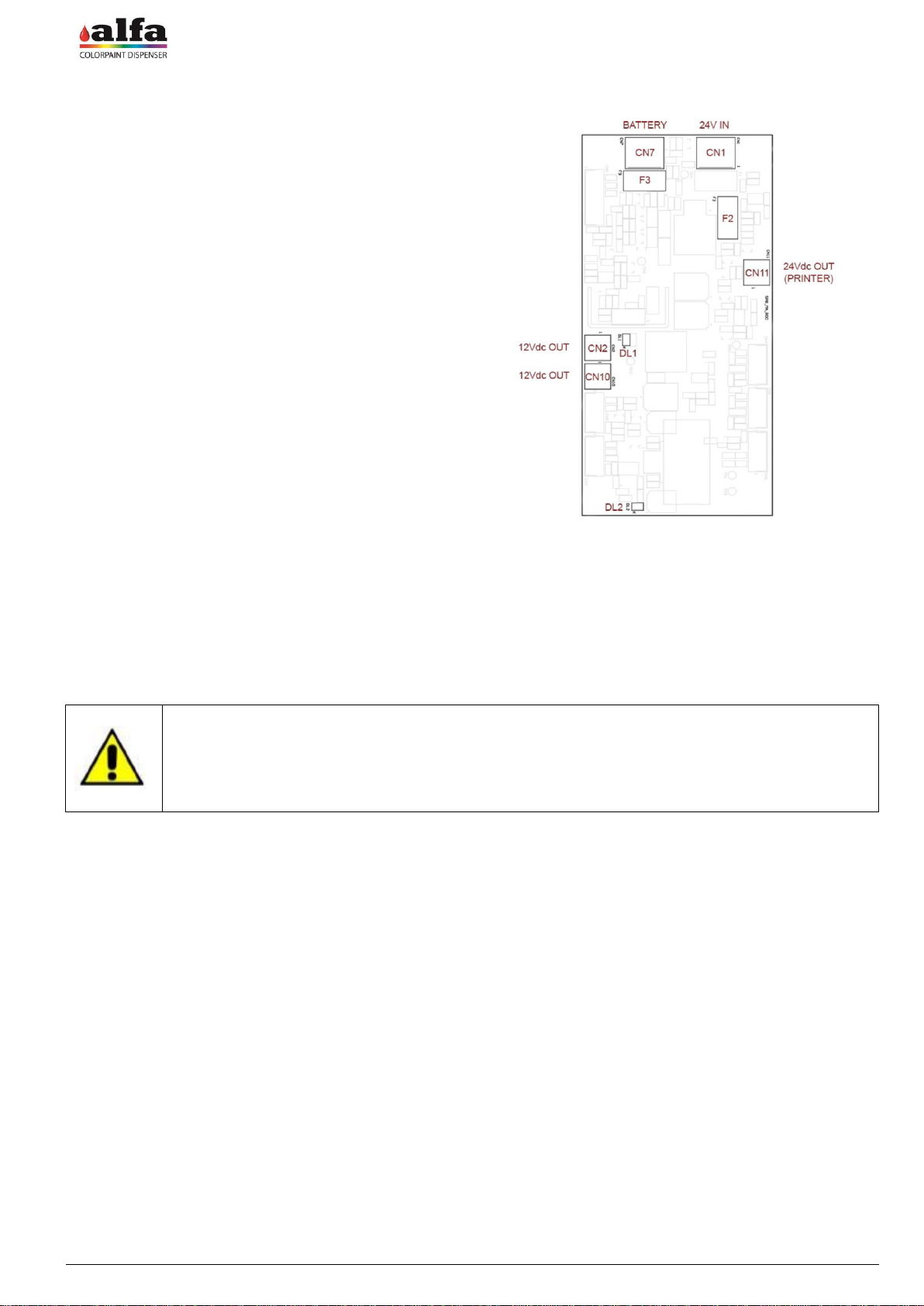
3.4. REPLACING THE POWER SUPPLY UNITS
In case of an electric fault in one or more power supply units of the machine, proceed as follows to replace them:
make sure the machine is disconnected from the
power supply as described in para. 2.0.3.
To reach the power supply unit compartment remove
the rear panel as described in paragraph 2.1.1. to
reach the electric panels, then remove the internal
protections as described in paragraph 2.1.2.
Disconnect the wiring between the power supply unit to
be replaced and the rest of the machine.
Remove the power supply unit by fitting a small flat
screwdriver in the suitable retaining tab and remove
the unit from the DIN bar.
Fit the new power supply unit manually on the DIN bar.
Reconnect the power supply unit to the wiring
according to the attached wiring diagram.
Reposition the previously removed protection panel.
WARNING: use only genuine spare parts supplied by the
manufacturer.
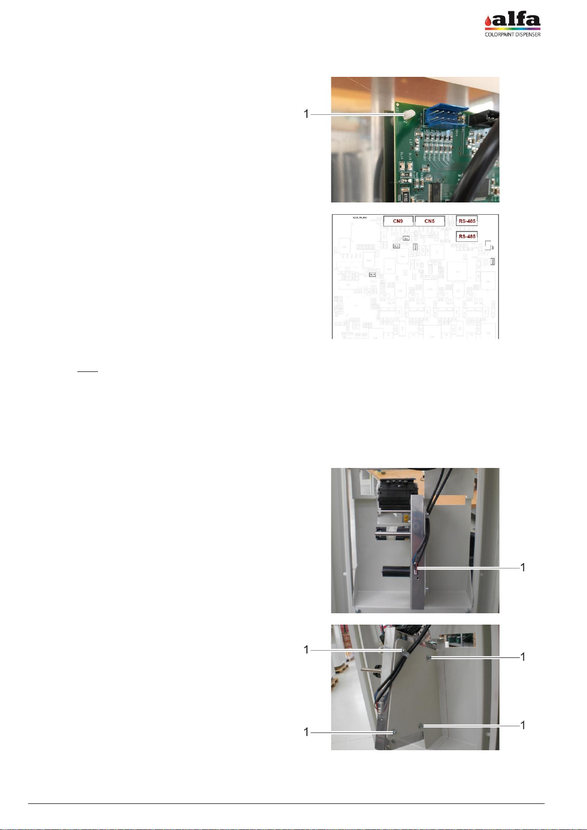
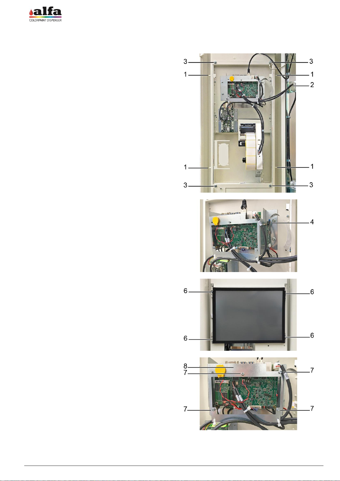
3.5. REPLACING THE MAX BOARD
To replace the MAB boards, proceed as follows:
make sure the machine is disconnected from the
power supply as described in para. 2.0.3.
Remove the rear panel as described in paragraph
2.1.1. to reach the electric panels, then remove the
internal protections as described in paragraph 2.1.2.
Disconnect the power supply and signal cables from
the board (1) to be replaced.
Remove the board by releasing it from the plastic
supports on its corners.
Insert a new board on the supports having care not to
damage its components.
WARNING: Use an already programmed board or the
suitable programmer to install the correct firmware. To
reprogramme the boards refer to chapter 4.
Restore the electric connections.
MAKE SURE THAT THE TERMINATION JUMPER ON
CN7 (2) IS PRESENT ON THE NEW BOARD.

Technical Manual –Color Tester
6
ELECTRIC REPAIRING OPERATIONS
EN
3.6. REPLACING THE SCCB BOARD
make sure the machine is disconnected from the
power supply as described in para. 2.0.3.
Remove the rear panel as described in paragraph
2.1.1. to reach the electric panels, then remove the
internal protections as described in paragraph 2.1.2.
Find the SCCB board to be replaced by referring to what is
indicated in paragraphs 2.1.2.2 and 2.1.2.3, then proceed
as follows.
Disconnect the power supply and signal cables from
the board.
Remove the board by releasing it from the supports (1)
on its corners.
Insert a new board on the supports having care not to
damage its components.
WARNING: Use a board already programmed with the
function of the replaced board. To reprogramme the board
refer to chapter 4.
Restore the previously disconnected connections
according to the wiring diagram.
MAKE SURE THAT THE TERMINATION JUMPER ON
CN7 (2) IS NOT PRESENT ON THE NEW BOARD.
3.7. REPLACING THE PRINTER
If the problems of label printing can not be solved with the ordinary maintenance operations, it is necessary to replace
the printer.
To replace the printer proceed as follows:
disconnect connector (1) located between the PC unit
and the printer. It is easy to see it on the machine left
side door.
Loosen the 4 M4X12 socket head screws + D4 washer
+ D5 washer for screw (1), having care not to damage
the wiring fixed to the upper left screw of the printer
support.
Position the new printer on the relevant support using
the just removed 4 M4X12 socket head screws + D4
and D5 washers.
Pay attention to reposition the wiring in the suitable
retainer on the support upper left corner.
Reconnect all connectors of the wirings between
printer and PC unit.

Technical Manual –Color Tester
EN
ELECTRIC REPAIRING OPERATIONS
7
3.8. REPLACING THE LINUX PC BOARD/DISPLAY UNIT
In case of malfunction replace the PC –display unit as follows:
open both doors (left and right) of the machine.
Remove the external cover of the LH door by
loosening the 4 M5X16 socket head screws + D5
washers (1) on the panel external corners.
Disconnect the connector between PC and display (4),
as shown in the figure and the power supply wiring of
display (5).
Remove the display by loosening the 4 M3X12 socket
head screws + D3 washers and the relevant nuts (6)
located on the corners of the display. Take care not to
pull the wirings at the back!
Disconnect the connectors located on display rear
side.
To remove the PC board, use a 2.5mm Allen wrench to
loosen the M3x6 screws (7) securing the stud bolts
(integral with the board) to the metal support (8).
Reassembly:
Replace the damaged components and refit the
display and the PC board using the previously
removed screws and nuts; then restore all the electric
connections.

Technical Manual –Color Tester
8
ELECTRIC REPAIRING OPERATIONS
EN
3.9. REPLACING THE SPB BOARD AND THE BATTERY
If any repair operation is required, replace the parts as follows:
Board replacement
Loosen the 4 M3x6 retaining screws (1) to release
board from support (2), then disconnect wirings and
proceed to replacement.
Battery replacement
Use a cutter to cut tie (3) securing battery (4) inside
support;
Disconnect battery and replace it with the spare one;
Secure battery to support using a new tie.
NOTE: FOR REPLACEMENT, USE ONLY GENUINE
SPARE PARTS SUPPLIED BY THE MANUFACTURER
3.10.REPLACING THE PAYMENT SYSTEM
In case of any problems to the payment system (optional), contact the Alfa technical service and request the
replacement with a genuine spare part.

Technical Manual –Color Tester
EN
ELECTRIC REPAIRING OPERATIONS
9
3.11.LTE ROUTER SETTINGS
When a hard-wired ethernet network is not available, it is still possible to obtain a remote connection to the machine
via an LTE Router.
A VPN client - duly installed and set up - is necessary to connect to the machine.
3.11.1. CONNECTION VIA VPN CLIENT ON WINDOWS 7 AND 10
To install the VPN Client, proceed as described below:
Open an internet browser at
https://openvpn.net/index.php/open-
source/downloads.html
Click “openvpn-install-2.4.4-I601.exe” (1) and
download the file.
Open the downloaded file, then press “Next” (2) on the
following screen page.
Check the boxes indicated in the figure on the side,
then press “Next”.
To connect to the machine via the VPN Client, proceed as
described below:
Download the file containing the login credentials sent
by Alfa via email.

Technical Manual –Color Tester
10
ELECTRIC REPAIRING OPERATIONS
EN
Save the file containing the credentials in
C:/programs/OpenVPN/Config
Make sure you save it as an “.opvn” file.
On Windows Toolbar, click the arrow icon “show
hidden icons” (3) then find the icon “OpenVPN” (4) in
the pop-up.
Right click on the icon and select “Connect” (5);
Press “Hide” (6) to close the following page;
After a few seconds a new pop-up will open on the
toolbar, near the clock indicating that the PC is
connected. This window could close automatically,
while the OpenVPN icon will become green.

Technical Manual –Color Tester
EN
ELECTRIC REPAIRING OPERATIONS
11
To connect to the machine, open your internet
browser.
In the address bar, enter the IP address of the
machine you wish to establish connection with, usually
indicated on the LTE router.
Enter the login credentials given by Alfa.
To disconnect from the machine, right click on OpenVPN
icon and select “Disconnect” (7).
3.11.2. CONNECTION VIA VPN CLIENT FROM ANDROID DEVICES
To install the VPN Client, proceed as described below:
From the Home screen of your device, open Play
Store.
In the search bar, type “openvpn for android”.
Click the green button (1) to install the application.
To connect to the machine via the VPN Client, proceed as
described below:
Download the file containing the login credentials sent
by Alfa via email.

Technical Manual –Color Tester
12
ELECTRIC REPAIRING OPERATIONS
EN
Run the app OpenVPN (2) previously installed.
Press symbol “+” present on the bar at top right of the
app screen.
Press “Import” (3).
Select the “.ovpn” file previously downloaded;

Technical Manual –Color Tester
EN
ELECTRIC REPAIRING OPERATIONS
13
Press on the check mark in the top right corner;
Press on the just-added file (4).
Press OK (5) on the next window.
Now the VPN status must be “Connected” (6).

Technical Manual –Color Tester
14
ELECTRIC REPAIRING OPERATIONS
EN
To connect to the machine, open your internet
browser.
In the address bar, enter the IP address of the
machine you wish to establish connection with, usually
indicated on the LTE router.
Enter the login credentials given by Alfa.
To disconnect from the machine, open the app
OpenVPN, then select the “Profiles” menu and press
“Disconnect” (7).

Technical Manual –Color Tester
EN
PROGRAMMING THE ELECTRONIC BOARDS
15
4. PROGRAMMING THE ELECTRONIC BOARDS
Depending on board version, programming can be carried out in either of two different methods:
Boards with no bootloader (programming via PICkit): see paragraph 4.1
Board with bootloader: see paragraph 4.2.
4.1. PROGRAMMING OF BOARDS WITH NO BOOTLOADER
4.1.1. PROGRAMMING DEVICES
Each SCCB board must have the dedicated firmware. For the SCCB boards, the firmware depends on the group to
control.
To programme the boards, use a suitable USB
programmer (1) and the MPLAB IDE programming
software.
If you do not have the suitable programmer, contact the
Alfa technical service.
The programmer uses a USB cable (2) for the connection
to the PC.
It could be useful to use an extension (3) to connect the
programmer to the boards positioned in points that are
hard to reach.
NOTE: The boards can be programmed both on the
machine and on the bench. To programme the boards they
must be powered by means of CN12 connector. If you use
the previously programmed boards for other functions it is
recommendable to disconnect the RS-485 serial
connectors before powering the machine.
4.1.2. INSTALLING THE MPLAB IDE SOFTWARE
The MPLAB IDE programming software can be downloaded from the reserved area of the website
www.alfadispenser.com or from the download area of the website http://www.microchip.com. The software can be
installed on a Windows, Linux or Mac PC.
4.1.3. PROGRAMMING WORKSPACE
To write the firmware it is necessary have a programming workspace to upload in the MPLAB IDE software as better
described below.
The programming workspaces are different for the SCCB
(4) boards and the MAB (5) board.

Technical Manual –Color Tester
16
PROGRAMMING THE ELECTRONIC BOARDS
EN
4.1.4. PROGRAMMING THE BOARDS
Download the workspace and the last available firmware version from the Alfa website reserved area, or contact the
Alfa technical service to receive the firmware. If you do not have the credentials to access the reserved area, contact
the Alfa technical service.
SCCB: according to the group to which the board must be connected, the following firmware is available:
up to 24 firmware versions (from c1 to c24) that can
be used on max. 12 colorant groups of the machine*;
up to 8 firmware versions (from b1 to b8) that can be
used on max. 2 base groups of the machine*;
Autocap group firmware;
can container firmware (from container 1 to 4);
lid can firmware (from cover 1 to 2);
X-axis firmware;
Y-axis firmware.
*: see the circuits enabled in the “Slave configuration” of
the “Device-Machine” menu of the Admin interface. For
further information consult the Software manual.
MABs and OTHER BOARDS:
MAB board Color Tester firmware;
SGBRDB board firmware (if present);
Firmware of other optional boards (HUTBRD, SPB,
etc.)
WARNING: CAREFULLY READ THE RELEASE NOTE TO CHECK THE FIRMWARE VERSION COMPATIBILITY
Connect the USB programmer, if necessary use an
extension, to CN1 connector of the board to be
programmed.
WARNING: Check that pin 1 of the programmer (4) is
connected to pin 1 of CN1 connector (5)!
Power the board by connecting the CN12 connector (6) to
the machine.
WARNING: do not connect the CN6 and CN8 connectors
of the RS-485 communication to avoid problems linked
with possible address conflicts.
Launch the MPLAB IDE software
Access to “File – Open workspace…” and select the
workspace of the board to programme (MAB or SCCB),
then select Open. For the SGBRD board, use SCCB
workspace.
WARNING: if you have connected a MAB board, upload
the “MABrd” workspace, whereas if you have connected
an SCCB board, upload the “Actuators” workspace (see
para. 4.3).
If message “No PICkit 3 Connected” is displayed, it means
that the programmer is not connected correctly.

Technical Manual –Color Tester
EN
PROGRAMMING THE ELECTRONIC BOARDS
17
When the programmer is correctly connected and
detected, the software will show the message “PICkit 3
detected”.
When connecting the board to the programmer and
powering it, the software shows the message “Target
Detected”.
besides the DEVICE ID of the connected board.
WARNING: If you upload a MAB Workspace and connect
an SCCB board (or vice versa), the software will show the
error “Target device ID does not match expected Device
ID”.
When everything is ready, programme the board in “File –
Import…” and select the suitable firmware version.
Select the suitable firmware version and select “Open”.
If the operation is completed successfully, the display will
show the message “Loaded….”

Technical Manual –Color Tester
18
PROGRAMMING THE ELECTRONIC BOARDS
EN
Select “Program” in the “Programmer” menu to start the
board programming.
At the end of the operation, the display will show the
message “Programming/Verify complete”.
Now it is possible to disconnect the power supply and the
programmer.
The board is ready to be used on the machine.
WARNING: Before programming a new board, make sure the loaded Workspace is the correct one. If this is not the
case, go back to the “File – Open workspace…” menu and upload the new workspace.
4.2. PROGRAMMING OF BOARDS WITH BOOTLOADER
4.2.1. SOFTWARE “BOOTLOADERAPP”
The most recent boards are preloaded with BOOT firmware for the management of the BootLoader, i.e. the application
that allows the updating of the machine control firmware.
NOTE: To program a board that does not feature preloaded BOOT, please contact Alfa technical service.
To program a hard-wired board via BootLoaderAPP, it is necessary to follow this procedure:
1. Shut off the machine;
2. connect the special cable Alfa USB BOOT LOADER (code 305001893) across CN13 connector of the MAB board
and a USB port of the PC/LAPTOP on which the application BootloaderAPP.exe is installed;
3. run BootloaderAPP;
4. switch the machine on.
TO USE A MACHINE IN BOOT MODE, YOU MUST FIRST CONNECT THE USB CABLE FROM MAB TO PC /
LAPTOP AND THEN SWITCH MACHINE ON.
BootLoaderAPP installation procedure is described in the following paragraph. If the software is already installed on
the PC, go directly to the following paragraph explaining software use for programming boards.

Operator Manual –Color Tester
EN
PROGRAMMING THE ELECTRONIC BOARDS
19
4.2.2. INSTALLATION OF “BOOTLOADERAPP”
If a version of the application is already present on the PC, you must first remove it before installing a new version.
In this case, run the installation software
and select option “Remove ALFA
Boot Manager”, then press “Finish”.
Wait until uninstall is completed and press “Close”.
To install the application:
1. Run the installation file .
The page on the side will open.
2. In the following window, select the software installation
path and select option “Everyone”, then press “Next >”.
3. When prompted, press “Next >” until completing the
installation procedure, then press “Close” to end the
installation procedure.

Technical Manual –Color Tester
20
PROGRAMMING THE ELECTRONIC BOARDS
EN
4.2.3. STARTING THE BOOTLOADER
Run BootloaderApp on the PC (the application is in the
folder selected in step 2 of the installation procedure).
The following window will open.
4.2.4. MAB FIRMWARE UPDATE
Check that the software detected the presence of a
MAB ‘Device attached’ (1)
Select the MAB board to be used by pressing the MAB
button (2) ‘Selected target device is now MAB’ +
‘QueryVerify command sent to MAB BOOT LOADER’
Select the Intel HEX file to be programmed, and press
‘Open Hex File’ (3) ‘HEX File Complete’
Proceed with Programming and Verification, by
pressing ‘Program/Verify’ (4) ‘’: wait for the final
message ‘Erase/Program/Verify Completed
Successfully’
If programming is successful, the ‘MAB’ button
becomes GREEN.
Table of contents
Popular Test Equipment manuals by other brands

Associated Research
Associated Research HypotMAX 7705 Operation and service manual

Elenco Electronics
Elenco Electronics XK-150 instruction manual

BLAUBERG
BLAUBERG Komfort EC D5B180 S14 installation guide

RIDGID
RIDGID SeekTech SR-24 Operator's manual

Bierer
Bierer 83280 operating instructions

ROD-L
ROD-L M100DC quick start guide

Tektronix
Tektronix 2215A Operator's instruction manual

Johnson Controls
Johnson Controls YORK RECOVERY PAK LD17585 operation & maintenance

Top Tronic
Top Tronic T1151 instruction manual

Wavetek
Wavetek ANT-20 operating manual

TRI Electronics
TRI Electronics GXL-18 owner's manual

Capelec
Capelec CAP2600 user manual