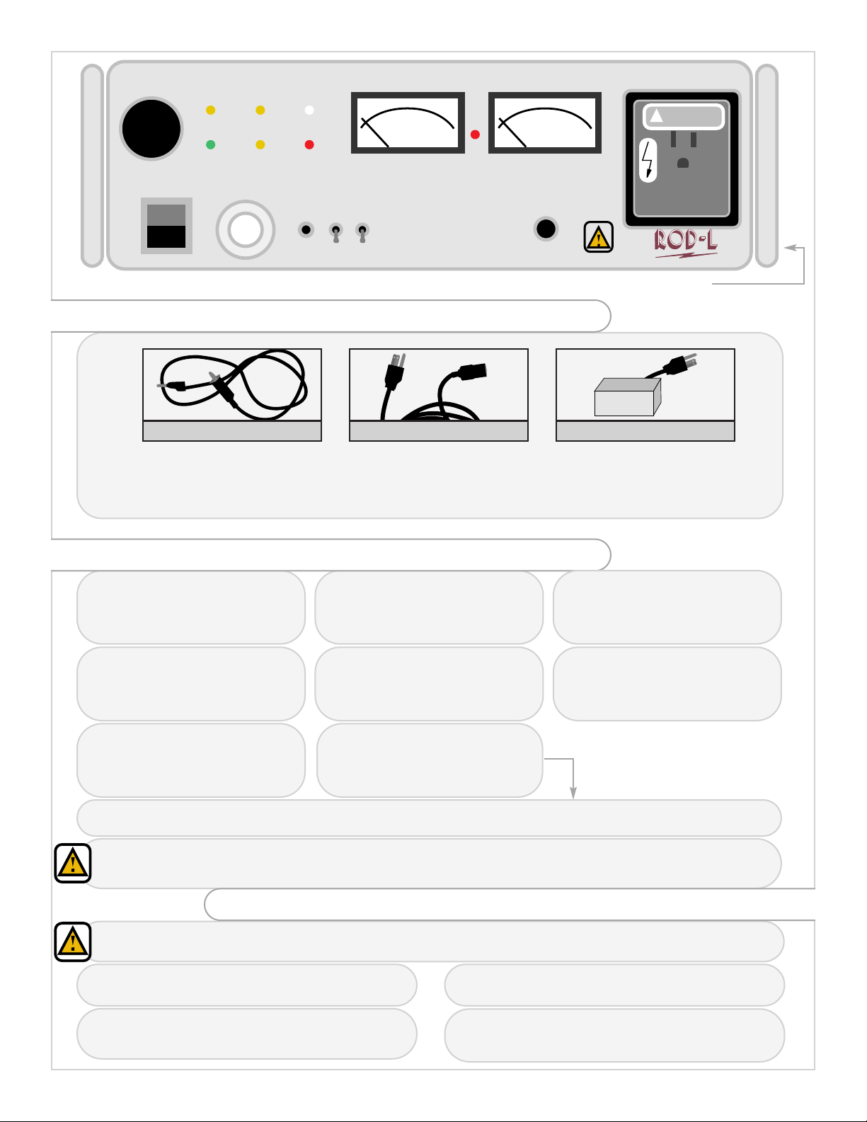
ROD-L M100DC User manual

-~
ARTISAN
®
~I
TECHNOLOGY
GROUP
Your definitive source
for
quality
pre-owned
equipment.
Artisan Technology
Group
Full-service,
independent
repair
center
with
experienced
engineers
and
technicians
on staff.
We
buy
your
excess,
underutilized,
and
idle
equipment
along
with
credit
for
buybacks
and
trade-ins
.
Custom
engineering
so
your
equipment
works
exactly as
you
specify.
•
Critical
and
expedited
services
•
Leasing
/
Rentals/
Demos
• In
stock/
Ready-to-ship
•
!TAR-certified
secure
asset
solutions
Expert
team
ITrust
guarantee
I
100%
satisfaction
All
tr
ademarks,
br
a
nd
names, a
nd
br
a
nd
s a
pp
earing here
in
are
th
e property of
th
e
ir
r
es
pecti
ve
ow
ner
s.
Find the Rod-L M100DC at our website: Click HERE

LINE POWER
READY TESTING FAIL
HV
ON
V-SET I-SET AC DANGER
START
RESET A
B
AC
DC
CHASSIS
GROUND SENSE
DC HIPOT TESTER
TOTAL OUTPUT CURRENT OUTPUT VOLTAGE
HIGH
VOLTAGE
DURING
TEST
QUICK START GUIDE
Phone:
(650) 322-0711 • (800) 548-6305
Fax: (650) 326-1993
Online: info@rodl.com • www.rodl.com
FOR MODELS:
M100DC
Artisan Technology Group - Quality Instrumentation ... Guaranteed | (888) 88-SOURCE | www.artisantg.com

1
LINE POWER
READY TESTING FAIL
HV
ON
V-SET I-SET AC DANGER
START
RESET A
B
AC
DC
CHASSIS
GROUND SENSE
DC HIPOT TESTER
TOTAL OUTPUT CURRENT OUTPUT VOLTAGE
HIGH
VOLTAGE
DURING
TEST
Ground Sense Wire Power Cord
metal part of handle
Device Under
Test (DUT)
DUT with 3 Prong Plug
(If you are testing a DUT with other than
a three prong grounded power cord, see
diagram below titled :“SET-UP TESTING
2-WIRE HIPOT”)
WHAT IS NEEDED FOR FOR SELF TEST AND BASIC DEVICE TESTING:
(The ground sense wire has a banana plug
which inserts into the “Chassis Ground
Sense post on the front panel of the
ROD-L unit and allegator clip to be
connected to the DUT)
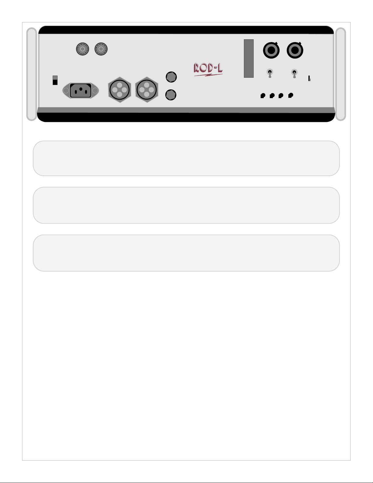
(The power cord connects to the rear
panel of the ROD-L unit and to any
grounded three-prong wall socket. Be
sure to set the line voltage on rear panel
to correct voltage i.e. 110 or 220)
1.a Make sure the line voltage
switch on rear panel is set to
the correct value for the wall
outlet (i.e. 110 or 220).
1.b Make sure the Test/Burn
switch on the rear pannel is
in the “Test” position. (See
manual for the correct usage
of the “Burn” position.)
1.dTurn on the Line Power on
the front panel of the ROD-L
Unit. 1.e Insert banana end of
GROUND SENSE WIRE into
the Chassis Ground Sense
post on the front panel of
ROD-L unit.
1.f Connect allegator clip of
ground sense wire to the metal
portion of the ROD-L unit
handle. Green Ready light will
light.
1.hPress “Start.”
After you press start, the “Testing” light will light for a brief period of time and then shut off.
This completes the self test.
Disconnecting the Ground Sense Wire from the Chassis Ground Sense post or the metal part of handle will cause
the test to fail. The red fail light will light, the audible alarm will sound and the unit will shut down. If this happens,
press the Reset button to turn off the alarm.
Make sure your test parameters are set correctly on the rear panel. If you are unsure or need to set any test
parameters, see instructions on the next page or refer to the manual.
2.a Plug the three-prong plug of the DUT into the front
panel receptacle of the ROD-L tester
2. BASIC DEVICE TESTING
2.b Connect the allegator clip of the Ground Sense
Wire to the DUT. Green Ready light should light.
2.c Press “Start.” Testing light will light for a brief
period of time and then return to ready mode if
test passes. 2.d If failure light and audible alarm turn on,
disconnect the DUT and press the Reset button
on tester to cancel alarm.
1. SELF TEST
1.g Make sure th AC/DC switch is in
the “DC” position. (The “AC”
position is only used when the
unit is being interfaced with an
AC hipot tester.)
1.cConnect the POWER CORD
to the rear of the ROD-L Unit
and plug into any three-prong
grounded wall outlet.
Artisan Technology Group - Quality Instrumentation ... Guaranteed | (888) 88-SOURCE | www.artisantg.com

2
V SET I SET
HV IN AC HIPOT HV OUT GT
REMOTE
FUSES
F1 F2
AC LINE
360 WATTS
AC CHASSIS
GROUND SENSE
LINE VOLTAGE BURN
TEST
SET
RUN
SET
RUN
A B A B
TEST RISE
CHASSIS
GND SENSE
1
1. Voltage Output Potentiometer (V-set):
This potentiometer is a 10-turn vernier dial on which each full rotation corresponds to 10% of the maximum voltage
output of the unit.To set the voltage, place the “run-set” switch in the “set” position and use the front panel voltmeter to
adjust the desired output voltage. Next, return the switch to the “run” position.
2. Current Trip Potentiometer (I-set):
This potentiometer is also a 10-turn vernier dial on which each full rotation corresponds to 10% of the maximum
current output of the unit.To set the trip point, place the “run-set” switch in the “set” position and use the front panel
current meter to adjust the desired current trip point. Next, return the switch to the “run” position.
3. Test Time and Voltage Rise Potentiometers:
These are all un-graduated 20-turn pots.The test time pots (the 2 left-most pots) allow the user to set the test time
anywhere from 1 second to 90 seconds.The rise-time pots (the 2 right-most pots) allow the user to set the rise-time
(ramp-rate) anywhere from 50 volts-per-second to 5000 volts-per-second.
Artisan Technology Group - Quality Instrumentation ... Guaranteed | (888) 88-SOURCE | www.artisantg.com

3
General Safety Guidelines for ROD-L Units
[Note:The following information applies to all ROD-L units and is also contained in the user’s manuals]
All ROD-L Electronics units are designed to assure maximum safety for the operators of the units.There are
no extraordinary precautions necessary during their operation and setup, however, due to the fact that high
voltage and high current are in use, there are some strongly recommended guidelines listed below:
There are a number of safety features built into ROD-L units that should never be removed or overridden.
These are; 1) the chassis ground sense circuit, 2) The internal components of the front panel high voltage
receptacle, 3) The recessed start button, 4) The alarm light and alarm tone, 5) The internal shut-down
circuitry of the units, 6) The reset switch.
The units should only be connected to three-wire grounded outlets.The safety of the outlets should be
periodically checked to insure safety.
Before initial operation, verify that the line input voltage selector switch (for 115 volts vs. 230 volts) is in the
correct position.
Due to the fact that high voltage is also present at the rear panel voltage connector
during operation of the unit, the connector when not used should be covered or the unit should be
positioned in such a way that the metal contacts within it cannot be accidentally touched.
Before changing fuses in the units, the power switch should be turned-off and the power cord disconnected.
Do not touch the device-under-test or its power cord while a test is in progress.
Following the above precautions should eliminate hazard to the operator of the ROD-L unit, but it should be
noted that the same common sense advice that would apply to the use of any electrical product should
always be used when operating ROD-L units.
Artisan Technology Group - Quality Instrumentation ... Guaranteed | (888) 88-SOURCE | www.artisantg.com

Artisan
Technology
Group
is
an independent supplier
of
quality pre-owned equipment
Gold-standard
solutions
Extend the life
of
your
critical industrial,
commercial, and military systems
with
our
superior service and support.
We
buy
equipment
Planning to
upgrade
your current
equipment? Have surplus equipment taking
up shelf space? We'll give it a
new
home.
Learn
more!
Visit us at artisantg.com for more info
on price quotes, drivers, technical
specifications, manuals, and documentation.
Artisan Scientific
Corporation
dba
Artisan
Technology
Group
is
not
an affiliate,
representative,
or
authorized
distributor
for
any
manufacturer
listed herein.
We're here to make your life easier.
How
can
we
help you today?
(217)
352-9330
Isales@artisantg.com Iartisantg.com
Table of contents
Other ROD-L Test Equipment manuals