Wavetek ANT-20 User manual

BN 3035/98.25
ANT-20, ANT-20E
Advanced Network Tester
STM-1 Mappings
BN 3035/90.01 to 90.06
Drop & Insert
BN 3035/90.20
in combination with
STM-1 Mappings
Software Version 7.20
Operating Manual
2

Please direct all enquiries to your
local Wavetek Wandel Goltermann sales
company. The addresses are given at the
end of this handbook.
Copyrights
This product orparts of it are based upon
Recommendations and/or Standards of the
Standardization Sector of the International
Telecommunication Union- ITU-T and/or of the
European Telecommunications Standards Institute -
ETSI. These Recommendations and Standards are
subject to copyrights of these organizations. Without
written permission of the ITU-T and/or ETSI it isnot
permitted to copy ITU-T Recommendations or ETSI
standards or parts thereof and/or make them available
to third parties.
Wavetek Wandel Goltermann
Eningen GmbH & Co.
Mühleweg 5, 72800 Eningen u. A.
© 2000
Author: MDD/TD
Translator: JohnNutley
Order no.: BN 3035/98.25
Edition: 13/00.07(V 7.20)
Previous edition:
12/00.04(V 7.1)
Subject to change without notice.
Our normal guarantee and delivery
terms apply.
Printed in Germany

ANT-20/ANT-20E STM-1 mapping
i
Contents
Specifications
1 STM-1 Mapping. . . . . . . . . . . . . . . . . . . . . . . . . . . . . . . . . . . . . . . . . .S-1
1.1 General information. . . . . . . . . . . . . . . . . . . . . . . . . . . . . . . .S-1
1.2 Tributary channel numbering. . . . . . . . . . . . . . . . . . . . . . . . .S-2
1.3 Scrambling/Descrambling . . . . . . . . . . . . . . . . . . . . . . . . . . .S-2
1.4 Overhead generation. . . . . . . . . . . . . . . . . . . . . . . . . . . . . . .S-3
1.4.1 Section Overhead (SOH) . . . . . . . . . . . . . . . . . . . . . . . . . . .S-3
1.4.2 STM-1 error insertion (anomalies). . . . . . . . . . . . . . . . . . . . . S-4
1.4.3 STM-1 alarm generation (defects). . . . . . . . . . . . . . . . . . . . . S-5
1.4.4 Pointer action generation . . . . . . . . . . . . . . . . . . . . . . . . . . . S-6
1.4.5 STM-1 error measurements (anomalies) . . . . . . . . . . . . . . .S-9
1.4.6 STM-1 alarm detection (defects). . . . . . . . . . . . . . . . . . . . .S-10
1.4.7 Measurement of AU and TU pointer actions. . . . . . . . . . . .S-11
1.4.8 VC-4 Path Overhead (POH), High Order . . . . . . . . . . . . . .S-12
1.4.9 VC-3 Path Overhead (POH), High Order . . . . . . . . . . . . . .S-13
1.4.10 Evaluation of Section Overhead (SOH) and
VC-4/VC-3 Path Overhead (POH). . . . . . . . . . . . . . . . . . . .S-14
1.5 C-12 mapping (2 Mbit/s in STM-1, AU-3/AU-4). . . . . . . . . .S-15
1.5.1 VC-12 Path Overhead contents . . . . . . . . . . . . . . . . . . . . .S-16
1.5.2 VC-12 error insertion (anomalies). . . . . . . . . . . . . . . . . . . .S-16
1.5.3 VC-12 alarm generation (defects). . . . . . . . . . . . . . . . . . . .S-17
1.5.4 VC-12 error measurements (anomalies). . . . . . . . . . . . . . .S-17
1.5.5 VC-12 alarm detection (defects) . . . . . . . . . . . . . . . . . . . . .S-18
1.5.6 VC-12 Path Overhead evaluation . . . . . . . . . . . . . . . . . . . .S-18
1.6 C-3 mapping (34/45 Mbit/s in STM-1, AU-3/AU-4) . . . . . . .S-19
1.6.1 VC-3 Path Overhead contents (Low Order) . . . . . . . . . . . .S-20
1.6.2 VC-3 error insertion (anomalies). . . . . . . . . . . . . . . . . . . . .S-20
1.6.3 VC-3 alarm generation (defects). . . . . . . . . . . . . . . . . . . . .S-21
1.6.4 VC-3 error measurement (anomalies). . . . . . . . . . . . . . . . . S-21
1.6.5 VC-3 alarm detection (defects) . . . . . . . . . . . . . . . . . . . . . .S-22
1.6.6 VC-3 Path Overhead evaluation . . . . . . . . . . . . . . . . . . . . .S-22
1.7 C-4 mapping (140 Mbit/s in STM-1/STS-3c). . . . . . . . . . . .S-23

STM-1 mapping ANT-20/ANT-20E
ii
1.8 C-11 mapping
(1.5 Mbit/s in STM-1, AU-3/AU-4, TU-11/TU-12) . . . . . . . . S-24
1.8.1 VC-11 Path Overhead contents . . . . . . . . . . . . . . . . . . . . . S-26
1.8.2 VC-11 error insertion (anomalies). . . . . . . . . . . . . . . . . . . . S-26
1.8.3 VC-11 alarm generation (defects). . . . . . . . . . . . . . . . . . . . S-27
1.8.4 VC-11 error measurements (anomalies). . . . . . . . . . . . . . . S-27
1.8.5 VC-11 alarm detection (defects). . . . . . . . . . . . . . . . . . . . . S-28
1.8.6 VC-11 Path Overhead evaluation. . . . . . . . . . . . . . . . . . . . S-28
1.9 C-2 mapping (6.3 Mbit/s in STM-1, AU-3/AU-4, TU-2) . . . . S-29
1.9.1 VC-2 Path Overhead contents . . . . . . . . . . . . . . . . . . . . . . S-30
1.9.2 VC-2 error insertion (anomalies). . . . . . . . . . . . . . . . . . . . . S-30
1.9.3 VC-2 alarm generation (defects). . . . . . . . . . . . . . . . . . . . . S-31
1.9.4 VC-2 error measurements (anomalies). . . . . . . . . . . . . . . . S-31
1.9.5 VC-2 alarm detection (defects). . . . . . . . . . . . . . . . . . . . . . S-32
1.9.6 VC-2 Path Overhead evaluation. . . . . . . . . . . . . . . . . . . . . S-32
1.10 Filler channel contents . . . . . . . . . . . . . . . . . . . . . . . . . . . . S-32
2 Drop & Insert / Through Mode . . . . . . . . . . . . . . . . . . . . . . . . . . . . S-33
2.1 Functions . . . . . . . . . . . . . . . . . . . . . . . . . . . . . . . . . . . . . . S-33
2.1.1 Clock generator. . . . . . . . . . . . . . . . . . . . . . . . . . . . . . . . . . S-34
2.1.2 Overhead generator . . . . . . . . . . . . . . . . . . . . . . . . . . . . . . S-35
2.1.3 Anomaly insertion . . . . . . . . . . . . . . . . . . . . . . . . . . . . . . . . S-35
2.1.4 Defect generation . . . . . . . . . . . . . . . . . . . . . . . . . . . . . . . . S-35
2.1.5 Pointer generation. . . . . . . . . . . . . . . . . . . . . . . . . . . . . . . . S-35
2.1.6 Measurements . . . . . . . . . . . . . . . . . . . . . . . . . . . . . . . . . . S-35
2.2 Signal outputs. . . . . . . . . . . . . . . . . . . . . . . . . . . . . . . . . . . S-36
2.2.1 AUXILIARY signal output [11], electrical. . . . . . . . . . . . . . . S-36
2.2.2 LINE/AUXILIARY signal output [13], electrical . . . . . . . . . . S-36
2.3 Signal inputs . . . . . . . . . . . . . . . . . . . . . . . . . . . . . . . . . . . . S-37
2.3.1 AUXILIARY signal input [10], electrical. . . . . . . . . . . . . . . . S-37
2.3.2 LINE/AUXILIARY signal input [12], electrical . . . . . . . . . . . S-38

ANT-20/ANT-20E STM-1 mapping
Specifications S-1
Specifications
These specifications apply to the options:
STM-1 Mapping
for ETSI tributaries
for ANSI tributaries
1 STM-1 Mapping
1.1 General information
Mapping/Demapping
The PDH tributaries are mapped into a STM-1 signal via the AU-4 or the AU-3 layer.
Container contents for all mapping options:
•Framed or unframed PDH test signal in one selected container
(6 Mbit/s, unframed only)
•PDH multiplex signal in one selected container
(together with Mux/Demux Chain 64k/140M or M13 option)
•Filling one selected container with a test pattern without justification bits
(Bulk Signal to O.181)
Drop & Insert
An additional Drop & Insert Option (BN 3035/90.20) for dropping or inserting tributary signals
(via sockets) is available in conjunction with the mapping options.
C-12 (2 Mbit/s in STM-1, AU-3/AU-4). . . . . . . . . . . . . . . . . . . . . . . . . . . . . . . . . .BN 3035/90.01
C-3 (34 Mbit/s in STM-1, AU-3/AU-4). . . . . . . . . . . . . . . . . . . . . . . . . . . . . . . . . .BN 3035/90.02
C-4 (140 Mbit/s in STM-1) . . . . . . . . . . . . . . . . . . . . . . . . . . . . . . . . . . . . . . . . . .BN 3035/90.03
C-2 (6 Mbit/s, unframed, in STM-1, AU-3/AU-4). . . . . . . . . . . . . . . . . . . . . . . . . .BN 3035/90.06
C-11 (1,5 Mbit/s in STM-1, AU-3/AU-4, TU-11/TU-12) . . . . . . . . . . . . . . . . . . . . .BN 3035/90.04
C-3 (45 Mbit/s in STM-1, AU-3/AU-4). . . . . . . . . . . . . . . . . . . . . . . . . . . . . . . . . .BN 3035/90.05
Drop & Insert . . . . . . . . . . . . . . . . . . . . . . . . . . . . . . . . . . . . . . . . . . . . . . . . . . .BN 3035/90.20

STM-1 mapping ANT-20/ANT-20E
S-2 Specifications
1.2 Tributary channel numbering
1.3 Scrambling/Descrambling
The STS-N signal is scrambled/descrambled as described in ITU-T G.707.
TU-3 TU-2 TU-12 TU-11 TS # TU-3 TU-2 TU-12 TU-11 TS # TU-3 TU-2 TU-12 TU-11 TS #
100 110 111 111 1 200 210 211 211 2 300 310 311 311 3
112 112 22 212 212 23 312 312 24
113 113 43 213 213 44 313 313 45
114 64 214 65 314 66
120 121 121 4 220 221 221 5 320 321 321 6
122 122 25 222 222 26 322 322 27
123 123 46 223 223 47 323 323 48
124 67 224 68 324 69
130 131 131 7 230 231 231 8 330 331 331 9
132 132 28 232 232 29 332 332 30
133 133 49 233 233 50 333 333 51
134 70 234 71 334 72
140 141 141 10 240 241 241 11 340 341 341 12
142 142 31 242 242 32 342 342 33
143 143 52 243 243 53 343 343 54
144 73 244 74 344 75
150 151 151 13 250 251 251 14 350 351 351 15
152 152 34 252 252 35 352 352 36
153 153 55 253 253 56 353 353 57
154 76 254 77 354 78
160 161 161 16 260 261 261 17 360 361 361 18
162 162 37 262 262 38 362 362 39
163 163 58 263 263 59 363 363 60
164 79 264 80 364 81
170 171 171 19 270 271 271 20 370 371 371 21
172 172 40 272 272 41 372 372 42
173 173 61 273 273 62 373 373 63
174 82 274 83 374 84
Table S-1 Channel numbers to G.707 (relationship between TU and time slot TS #)

ANT-20/ANT-20E STM-1 mapping
Specifications S-3
1.4 Overhead generation
1.4.1 Section Overhead (SOH)
Standard Overhead, STM-1 (hex)
XX: Inserted by parity formation (B1, B2)
H1 and H2 depend on the pointer address setting (pointer address = 0 is shown), H3 depends
on whether or not a pointer action takes place.
SOH byte contents
•Static bytes: all except B1, B2, H1, H2, H3
•Overhead sequence m, n, p: all except B1, B2, H1, H2, H3
•Trace Identifier (Length = 16 frames with CRC7 formation): J0
•Dynamic bytes filled using PRBS 11: E1, F1, E2
•Dynamic byte groups filled using PRBS 11: D1 to D3, D4 to D12
•Dynamic bytes filled via DCC/ECC interface (V.11): E1, F1, E2
•Dynamic byte groups filled via DCC/ECC interface (V.11): D1 to D3, D4 to D12, K1 to K2
S O H
123456789
1A1
F6 A1
F6 A1
F6 A2
28 A2
28 A2
28 J0
01 ––
AA ––
AA
2B1
XX ––
00 ––
00 E1
00 ––
00 ––
00 F1
00 ––
00 ––
00
3D1
00 ––
00 ––
00 D2
00 ––
00 ––
00 D3
00 ––
00 ––
00
4a H1
68 Y
9B Y
9B H2
00 ––
FF ––
FF H3
00 H3
00 H3
00 for AU-4
4b H1
68 H1
68 H1
68 H2
00 H2
00 H2
00 H3
00 H3
00 H3
00 for AU-3
5B2
XX B2
XX B2
XX K1
00 ––
00 ––
00 K2
00 ––
00 ––
00
6D4
00 ––
00 ––
00 D5
00 ––
00 ––
00 D6
00 ––
00 ––
00
7D7
00 ––
00 ––
00 D8
00 ––
00 ––
00 D9
00 ––
00 ––
00
8D10
00 ––
00 ––
00 D11
00 ––
00 ––
00 D12
00 ––
00 ––
00
9S1
00 Z1
00 Z1
00 Z2
00 Z2
00 M1
00 E2
00 ––
00 ––
00
Table S-2 SOH contents

STM-1 mapping ANT-20/ANT-20E
S-4 Specifications
1.4.2 STM-1 error insertion (anomalies)
When Rate triggering is selected a bit error rate is inserted.
The insertion of errors (anomalies) and alarms (defects) are mutually exclusive. The first
action selected is active. The second action is rejected.
Error insertion (anomalies) . . . . . . . . . . . . . . . . . . . . . . . . . . . . . . . . . .B1, B2, B3 parity errors,
FAS word errors, MS-REI, HP-REI,
bit errors in test pattern (TSE),
code errors (single errors only)
Trigger types . . . . . . . . . . . . . . . . . . . . . . . . . . . . . . . . . . . . . . . . . . . . . . . . . . . . . . . . . . . Single
or Rate
Anomaly Single Rate1Burst m, n (frames)
FAS yes 2E-3 to 1E-10 m = 1 to 196000
B1 yes 2E-4 to 1E-10 m = 1 to 196000
B2 yes 2E-3 to 1E-10 m = 1 to 196000
MS-REI yes 2E-3 to 1E-10 m = 1 to 196000
B32yes 2E-4 to 1E-10 m = 1 to 196000
HP-REI yes 2E-4 to 1E-10 m = 1 to 196000
TSE yes 1E-2 to 1E-8 -
CODE yes - -
1 Mantissa: 1 to 9 (only 1 for TSE), exponent: -1 to -10 (whole numbers)
2Static error insertion, can be edited using an 8-bit mask (x = don’t care, 1 = insert error)
Table S-3 Available anomalies (STM-1) and trigger modes

ANT-20/ANT-20E STM-1 mapping
Specifications S-5
1.4.3 STM-1 alarm generation (defects)
.
The insertion of alarms (defects) and errors (anomalies) are mutually exclusive. The first
action selected is active. The second action is rejected.
Defect Test sensor
function Test sensor thresholds
On/Off M in N |----t1----|
|------t2------|
LOS1yes M = 800 bis 7200
N = 1600 bis 8000 t1 = 0.1 bis 60.0 s
t2 = 0.2 bis 600 s
LOF yes M = 1 to N - 1
N = 1 to 80002t1 = 0.1 to 60.0 s
t2 = 0.2 to 600 s
RS-TIM yes - -
MS-AIS yes M = 1 to N - 1
N = 1 to 8000 t1 = 0.1 to 60.0 s
t2 = 0.2 to 600 s
MS-RDI yes M = 1 to N - 1
N = 1 to 8000 t1 = 0.1 to 60.0 s
t2 = 0.2 to 600 s
AU-LOP yes M = 1 to N - 1
N = 1 to 8000 t1 = 0.1 to 60.0 s
t2 = 0.2 to 600 s
AU-AIS yes M = 1 to N - 1
N = 1 to 8000 t1 = 0.1 to 60.0 s
t2 = 0.2 to 600 s
HP-UNEQ yes M = 1N to N - 1
N = 1 to 8000 t1 = 0.1 to 60.0 s
t2 = 0.2 to 600 s
HP-PLM yes M = 1N to N - 1
N = 1 to 8000 t1 = 0.1 to 60.0 s
t2 = 0.2 to 600 s
HP-RDI yes M = 1 to N - 1
N = 1 to 8000 t1 = 0.1 to 60.0 s
t2 = 0.2 to 600 s
HP-TIM yes - -
1 Only in conjunction with an optical interface
2 Included in mainframe (no option required)
Table S-4 Available defects (STM-1)
STM-1 mapping ANT-20/ANT-20E
S-6 Specifications
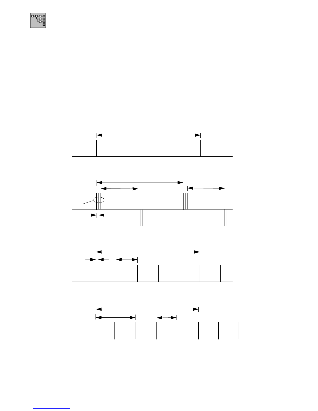
1.4.4 Pointer action generation
Stimulation
Pointer sequences
On all pointer levels to ITU-T G.783
Fig. S-1 Perodic (single/multiple) pointers with identical polarity
Fig. S-2 Periodic (single/multiple) pointers with different polarity
Fig. S-3 Periodic pointers with one double pointer
Fig. S-4 Periodic pointers with one missing pointer
T1, T4: 0.25 ms to 600 s . . . . . . . . . . . . . . . . . . . . . . . . . . . . . . . . . . . . . (2 to 4800000 frames)
T2, T3: 0.25 ms to 10 s . . . . . . . . . . . . . . . . . . . . . . . . . . . . . . . . . . . . . . . . (2 to 80000 frames)
T5: 0 ms to 600 s. . . . . . . . . . . . . . . . . . . . . . . . . . . . . . . . . . . . . . . . . . . (0 to 4800000 frames)
n: 1 to 2000
T4
T1
T2
n pointers
T4 T1
T2
T4
T3
T4 T2
T5
ANT-20/ANT-20E STM-1 mapping
Specifications S-7
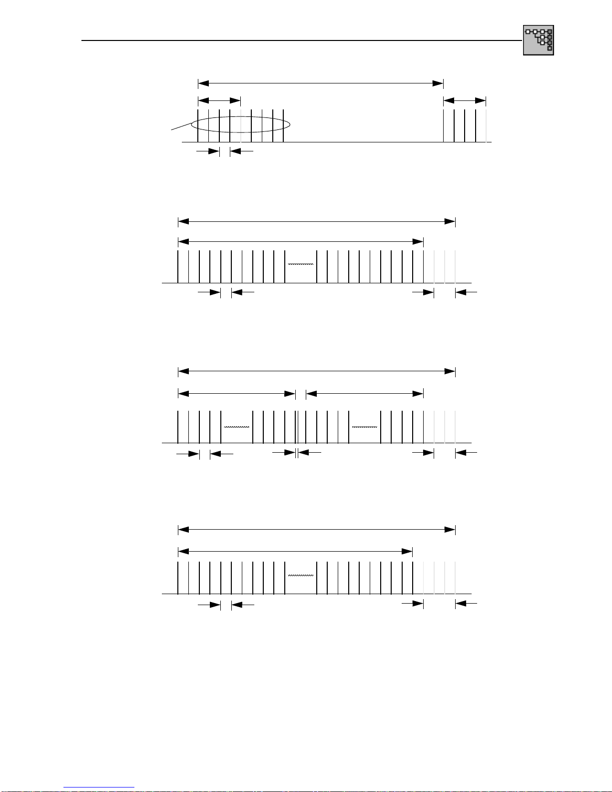
Fig. S-5 Pointer burst with missing pointers
Fig. S-6 ”87-3” sequence
Fig. S-7 ”43-44” sequence with double pointer
Fig. S-8 ”86-4” sequence with missing pointer
T2
T4
T5
T5
n Pointer
87 pointer actions
3 x no pointer action
T2
T4
43 pointer actions
3 x no pointer action
T3
44 pointer actions
T2
T4
86 pointer actions
4 x no pointer action
T2
T4

STM-1 mapping ANT-20/ANT-20E
S-8 Specifications
Pointer jumps
Pointer jump from pointer value A to pointer value B (also setting a new pointer).
Pointer jumps are executed with NDF.
Pointer range A + B:
AU-4/AU-3 pointer . . . . . . . . . . . . . . . . . . . . . . . . . . . . . . . . . . . . . . . . . . . . . . . . . . . . . 0 to 782
TU-3 pointer. . . . . . . . . . . . . . . . . . . . . . . . . . . . . . . . . . . . . . . . . . . . . . . . . . . . . . . . . . 0 to 764
TU-2 pointer. . . . . . . . . . . . . . . . . . . . . . . . . . . . . . . . . . . . . . . . . . . . . . . . . . . . . . . . . . 0 to 427
TU-12 pointer. . . . . . . . . . . . . . . . . . . . . . . . . . . . . . . . . . . . . . . . . . . . . . . . . . . . . . . . . 0 to 139
TU-11 pointer. . . . . . . . . . . . . . . . . . . . . . . . . . . . . . . . . . . . . . . . . . . . . . . . . . . . . . . . . 0 to 103

ANT-20/ANT-20E STM-1 mapping
Specifications S-9
1.4.5 STM-1 error measurements (anomalies)
Evaluation
Display
of anomalies via LEDs:
Display of errors as count or ratio values (equivalent bit error ratio): When calculating the ratio
value, correction formulae are used for the anomalies B1, B2, B3 and BIP-2 as well as MS-REI,
HP-REI and LP-REI. These take into account that a multiple error in the same bit can lead to
clearance of the error.
All errors (anomalies) are counted simultaneously and stored.
Gate times . . . . . . . . . . . . . . . . . . . . . . . . . . . . . . . . . . . . . . . . . . . . . . . . . . . . .1 to 99 seconds
or 1 to 99 minutes
or 1 to 99 hours
or 1 to 99 days
Intermediate results . . . . . . . . . . . . . . . . . . . . . . . . . . . . . . . . . . . . . . . . . . . . . .1 to 99 seconds
or 1 to 99 minutes
CURRENT LED (red) is on when the anomaly is present
HISTORY LED (yellow) is on if the anomaly has occurred at least once during the current
measurement interval.
Anomaly LED
OOF -155 LOF/OOF
FAS-155 -
B1 B1/B2
B2 B1/B2
MS-REI -
B3 B3
HP-REI -
CRC-4 FAS/CRC
E-Bit -
TSE TSE
CODE -
Table S-5 LED display of possible anomalies (STM-1)

STM-1 mapping ANT-20/ANT-20E
S-10 Specifications
1.4.6 STM-1 alarm detection (defects)
Evaluation
All alarms (defects) which occur are evaluated simultaneously where possible and stored.
Storage takes place only within a started measurement interval.
.
Display
of defects via LEDs:
Time resolution of defects . . . . . . . . . . . . . . . . . . . . . . . . . . . . . . . . . . . . . . . . . . . . . . . . 100 ms
CURRENT LED (red) is on when the defect is present
HISTORY LED (yellow) is on if the defect has occurred at least once during the current
measurement interval.
Defect LED
LOS LOS
LOF-155 LOF/OOF
RS-TIM -
MS-AIS MS-AIS
MS-RDI MS-RDI
AU-LOP AU-LOP
AU-AIS AU-AIS
HP-UNEQ HP-UNEQ
HP-PLM HP-PLM
HP-RDI HP-RDI
HP-TIM -
LSS LSS
Table S-6 LED display of possible defects (STM-1)

ANT-20/ANT-20E STM-1 mapping
Specifications S-11
1.4.7 Measurement of AU and TU pointer actions
Evaluation
All pointers in the selected path are shown as absolute values and the direction and number of
pointer movements is detected and counted.
NDF (New Data Flag) is recorded and counted.
Display
of:
•Number of pointer operationsseparated for AU and TU pointer:
Increments, decrements, sum of increments + decrements,
difference of increments - decrements
•Pointer address
•Number of NDF events
•Corresponding clock deviation
•AU-NDF and TU-NDF can be indicated by the LED display (front panel)
(Application Manager - “Configuration” menu - LED Display ...):
– the “AU-LOP/LOP-P” LED indicates “AU-NDF” in addition to “AU-LOP”
– the “TU-LOP/LOP-V” LED indicates “TU-NDF” in addition to “TU-LOP”
Absolute pointer values, increments, decrements, sum of increments + decrements and NDF
are displayed as a histogram with selectable time resolution in seconds, minutes, hours or days.
Printout
Absolute pointer values, increments, decrements, sum of increments + decrements and NDF
are printed out as a table with 1 second time resolution.
STM-1 mapping ANT-20/ANT-20E
S-12 Specifications
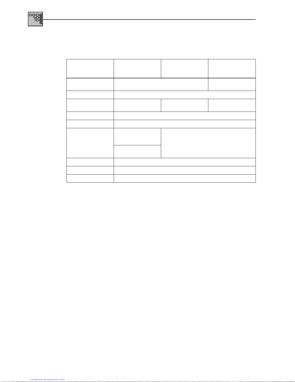
1.4.8 VC-4 Path Overhead (POH), High Order
Standard overhead
VC-4 POH byte contents
•Static bytes: all except B3, H4
•Overhead sequence m, n, p: J1, C2, G1, F2, F3, K3, N1
•Trace Identifier (Length = 16 frames with CRC7 formation): J1
•Dynamic byte filled using PRBS 11: F2
•Dynamic bytes filled via DCC/ECC interface (V.11): F2, K3, N1
•H4 sequence, switchable, 4/48 byte
POH byte Option 3035/90.01,
Option 3035/90.04,
Option 3035/90.06
Option 3035/90.02 and
Option 3035/90.05 Option 3035/90.03
J1 (ASCII) “WG HP-TRACE” “VC-4 MAPPING”
“VC-4 BULK”
B3 (hex) Inserted by parity formation
C2 (hex) “02” “04” “12” for MAPPING
“FE” for BULK
G1 (hex) “00”
F2 (hex) “00”
H4 (hex) “FC”, ”FD”, ”FE”, ”FF”
sequence across
4 frames
“FF”
48-byte-sequence as
G.709
F3 (hex) “00”
K3 (hex) “00”
N1 (hex) “00”
Table S-7 POH contents

ANT-20/ANT-20E STM-1 mapping
Specifications S-13
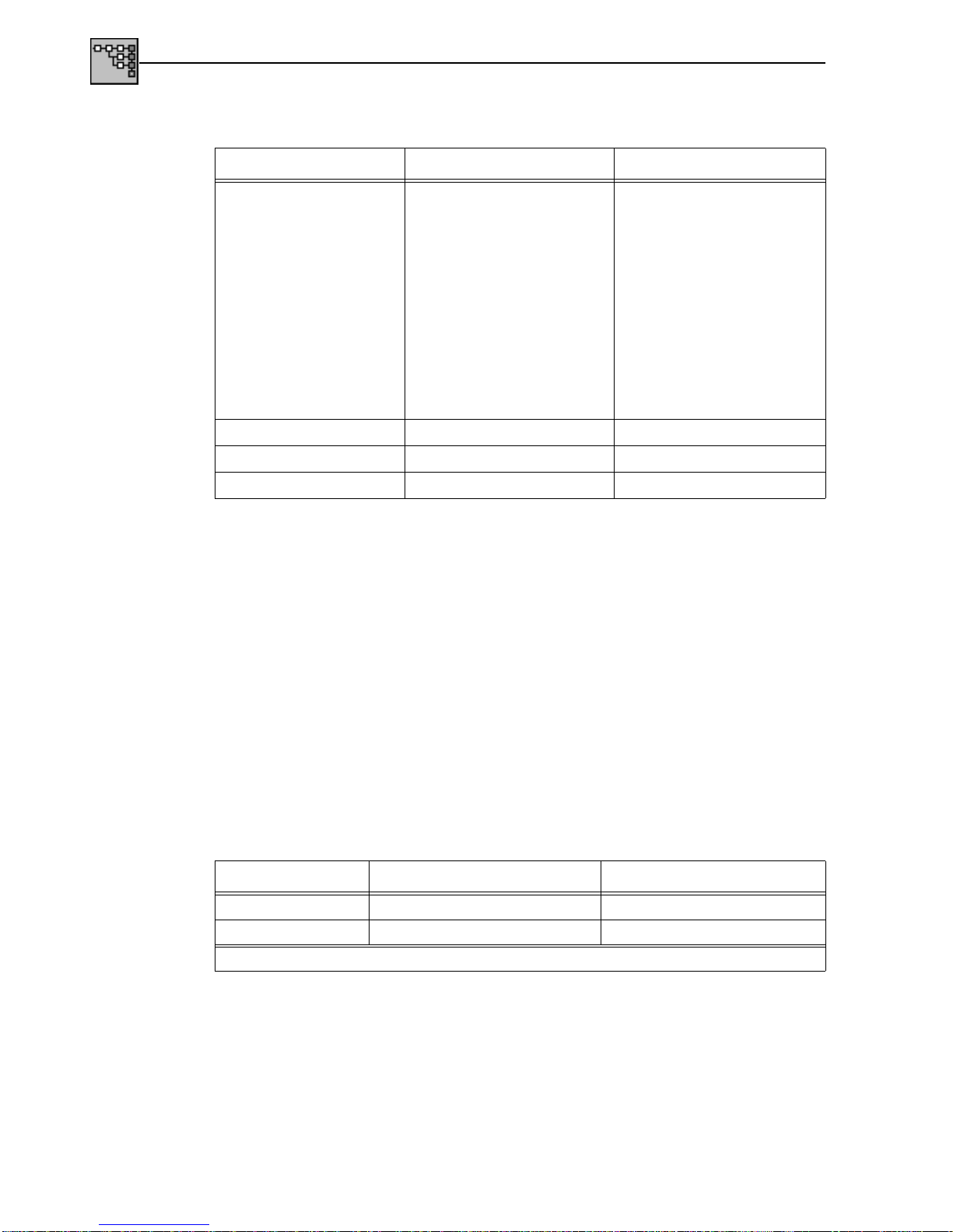
1.4.9 VC-3 Path Overhead (POH), High Order
Standard overhead
VC-3 POH byte contents
•Static bytes: all except B3, H4
•Overhead sequence m, n, p: J1, C2, G1, F2, F3, K3, N1
•Trace Identifier (Length = 16 frames with CRC7 formation): J1
•Dynamic byte filled using a pseudo-random sequence: F2
•Dynamic bytes filled by DCC/ECC interface (V.11): F2, K3, N1
•H4 sequence, switchable, 4/48 byte
POH byte Option 3035/90.01, Option 3035/90.04
and Option 3035/90.06 Option 3035/90.02 and
Option 3035/90.05
Measured channels Fill channels Measured channels Fill channels
J1 (ASCII) “WG HP-TRACE” “WG IDLE” “VC-3 Mapping”
“VC-3 Bulk” “WG IDLE”
B3 (hex) Inserted by parity formation
C2 (hex) “02” “02” “04” for mapping
“FE” for bulk “04”
G1 (hex) “00”
F2 (hex) “00”
H4 (hex) “FC”, “FD”, “FE”, “FF” sequence across
4 frames “FF”
48-byte-sequence asG.709
F3 (hex) “00”
K3 (hex) “00”
N1 (hex) “00”
Table S-8 POH contents

STM-1 mapping ANT-20/ANT-20E
S-14 Specifications
1.4.10 Evaluation of Section Overhead (SOH) and VC-4/VC-3 Path Overhead (POH)
Display
Evaluation
Bit error measurement
Output
of complete SOH and POH . . . . . . . . . . . . . . . . . . . . . . . . . . . . . . . . . . . . . . . . . . .hexadecimal
of Trace Identifier J0, J1 . . . . . . . . . . . . . . . . . . . . . . . . . . . . . . . . . . . . . . . . . . ASCII, plain text
using PRBS 11 (bytes). . . . . . . . . . . . . . . . . . . . . . . . . . . . . . . . . . . . . . . . . . . . . E1, F1, E2, F2
using PRBS 11 (byte groups) . . . . . . . . . . . . . . . . . . . . . . . . . . . . . . . . . . .D1 to D3, D4 to D12
as bytes via DCC/ECC interface (V.11). . . . . . . . . . . . . . . . . . . . . . . . . .E1, F1, E2, F2, K3, N1
as byte groups via DCC/ECC interface (V.11). . . . . . . . . . . . . . .D1 to D3, D4 to D12, K1 to K2

ANT-20/ANT-20E STM-1 mapping
Specifications S-15
1.5 C-12 mapping (2 Mbit/s in STM-1, AU-3/AU-4)
Option: BN 3035/90.01
Mapping structure: AU-4
Fig. S-9 Mapping structure: 2 Mbit/s →C-12 →AU-4 →STM-1
Mapping structure: AU-3
Fig. S-10 Mapping structure: 2 Mbit/s →C-12 →AU-3 →STM-1
Mapping structure: 2 Mbit/s →C-12 →AU-3 →STM-0; option 3035/98.13 required
Mapping method
The following modes are available:
•Asynchronous mode
•Byte-synchronous mode (floating)
STM-1 mapping ANT-20/ANT-20E
S-16 Specifications
1.5.1 VC-12 Path Overhead contents
Measurement channel byte contents (VC-12)
•Static bytes: all except bits 1-2 of V5
•Overhead sequence m, n, p: J2, N2, K4
•Trace Identifier (Length = 16 frames with CRC7 formation): J2
•Dynamic bytes filled by DCC/ECC interface (V.11): N2
Filler channel byte contents (VC-12)
Fixed, non-editable as in (seeTab. S-9).
1.5.2 VC-12 error insertion (anomalies)
The following anomalies can be inserted in addition to the error types specified in
Sec. 1.4.2,Page S-4:
Error insertion refers to the selected measurement channel.
POH byte Measurement channel Filler channels
V5 (binary)
LP-BIP (bits 1-2)
LP-REI (bit 3)
LP-RFI (bit 4)
Path Label (bit 5-7)
LP-RDI (bit 8)
Inserted by parity formation
“0”
“0”
“010” for asynchronous mode
“100” for byte-synchronous mode
“110” for bulk signal
“0”
Inserted by parity formation
“0”
“0”
“010” for asynchronous mode
“100” for byte-synchronous mode
“0”
J2 (ASCII) “WG LP-TRACE” “WG IDLE”
N2 (hex) “00” “00”
K4 (hex) “00” “00”
Table S-9 VC-12 POH (Standard Overhead) contents
Anomaly Single Rate
BIP-21yes 2E-4 to 1E-10
LP-REI yes 2E-4 to 1E-10
1Static error insertion, can be edited using a 2-bit mask (x = don’t care, 1 = insert error)
Table S-10 Additional available anomalies (VC-12)
Other manuals for ANT-20
8
This manual suits for next models
1
Table of contents
Other Wavetek Test Equipment manuals

Wavetek
Wavetek ANT-20 User manual

Wavetek
Wavetek ANT-20 User manual

Wavetek
Wavetek ANT-20 User manual

Wavetek
Wavetek ANT-20 User manual

Wavetek
Wavetek 147 User manual

Wavetek
Wavetek ANT-20 User manual

Wavetek
Wavetek ANT-20 User manual

Wavetek
Wavetek ANT-20 User manual

Wavetek
Wavetek SF10 User manual

Wavetek
Wavetek ANT-20 User manual


