Alfalaval Optigo CD User manual

ORIGINAL INSTRUCTIONS
AHE00046EN 1904
Alfa Laval Optigo CD
Instruction manual
• Product description
• Product labels
• Unpacking & lifting
• Installation
• Maintenance
• Spare parts

AHE00046EN 1904
2
Alfa Laval is a trademark registered and owned by Alfa Laval Corporate AB.
Alfa Laval reserves the right to change specification without prior notification.
Index
1. Important information
1.1 Disclaimer...................................................................................................................................3
1.2 Intended use...............................................................................................................................3
1.3 Where to nd product information ..............................................................................................3
2. Product description
2.1 General information and application...........................................................................................4
2.2 Standard conguration ...............................................................................................................4
2.3 Options.......................................................................................................................................5
2.4 Code description ........................................................................................................................5
3. Product labels...........................................................................................................................6
4. Unpacking and lifting...............................................................................................................8
5. Installation
5.1 Mounting dimensions .................................................................................................................9
5.2 Mounting bracket......................................................................................................................10
5.3 Technical spaces......................................................................................................................10
5.4 Refrigerant connections ...........................................................................................................10
5.5 Drain line ..................................................................................................................................10
5.6 Electrical connections...............................................................................................................11
5.7 Electric defrost capacities.........................................................................................................16
6. Maintenance
6.1 Fan replacement ......................................................................................................................17
6.2 Driptray.....................................................................................................................................17
6.3 Side covers...............................................................................................................................18
6.4 Coil heater elements replacement............................................................................................18
6.5 Driptray heater elements replacement .....................................................................................18
7. Spare parts..............................................................................................................................19

AHE00046EN 1904
3
Alfa Laval is a trademark registered and owned by Alfa Laval Corporate AB.
Alfa Laval reserves the right to change specification without prior notification.
1 Important information
1.1 Disclaimer
This Instruction Manual applies to all Alfa Laval Optigo CD air cooler products and is supplied in
combination with the Alfa Laval Air Cooler Product Manual AHE00042. Both manuals must be
carefully examined and instructions should be followed up at all times. Alfa Laval does not accept
liability for any damage resulting from non-compliance to the instructions as given in the manuals
and order-related documents.
1.2 Intended use
Air coolers are partly completed machinery according to Machine Directive 2006/42/EC and are
intended for incorporation in cooling systems. Declarations of Incorporation are available on www.
alfalaval.com. The units may not be put into operation until the conformity of the complete machine
or cooling system has been declared according to the following standards and directives:
• Pressure Equipment Directive 2014/68/EU
• Machine Directive 2006/42/EC
• Low Voltage Directive 2014/35/EU
• Electrical Equipment of Machines IEC 60204-1
• Electro Magnetic Compatibility 2014/30/EU
• Any applicable local or national legislation
1.3 Where to find product information
Detailed technical data for individual product models are available in order related documents, on
the product label and in product data sheets. Comprehensive technical information for all Alfa Laval
air heat exchanger products is available on-line on www.alfalaval.com. This includes:
• Product manuals
• Instruction manuals
• Product leaflets & brochures
• Product data sheets (selection software)
• Dimensional drawings
• Electrical wiring diagrams
• Certificates
Alfa Laval offers world-wide service and support in over 55 countries. In case of any questions
or uncertainty please contact your local Alfa Laval representative. Contact addresses are available
at www.alfalaval.com.
Optigo CD

AHE00046EN 1904
4
Alfa Laval is a trademark registered and owned by Alfa Laval Corporate AB.
Alfa Laval reserves the right to change specification without prior notification.
2 Product description
2.1 General information and application
Optigo CD are commercial dual discharge air coolers for general application in small to medium-
sized cooling, freezing and working rooms. Low air velocity and noise level make them especially
suitable for refrigerated working and processing rooms.
• Refrigerants: HFO/HFC DX (CDE), CO2 DX (CDX) and brine (CDW).
• Room temperatures: +10 to -30 °C.
• Capacity range (SC2): 0.8 up to 16.5 kW.
• Air volume: 600 up to 8400 m3/h.
Model Refrigerant Design pressure Test pressure
CDE HFO/HFC 40 bar 57 bar
CDX CO2 80 bar 114 bar
CDW Brine 10 bar 14.3 bar
2.2 Standard configuration
• Innovative coil manufactured from internally grooved Cu tubes and aluminium fins, smooth tub-
ing for brine applications and dedicated thicker tubes for CO2application.
• Optigo CD coolers are available with 1 to 4 fans. Fan diameters 300 or 400 mm blowing through
the coil. All models are standard fitted with AC fan motors in two fan speed executions (noise
levels) H/L. EC fan motors optional.
Motors with dynamically and statically balanced external rotors, manufactured in accordance
with VDE 0530/12.84. Integrated thermo contacts (Clixon) standard for 3-phase AC motors. All
single phase motors protected by an integrated internal overload switch. Electronically integrated
overload protection for EC fan motors.
• Durable aluminium alloy casing, powder epoxy coated RAL 9002. Hinged lateral driptrays with
dismountable central drain box. Fully dismountable and openable casing for cleaning purposes.
Pre-cut passages for multiple choice connections. Internal air deflectors enhance coil efficiency.
• All CD300 are delivered in wood-reinforced cardboard boxes, suitable for safe stacking. All
CD400 models are delivered in wooden crates in mounting position.
• Fitted with schräder valve on the suction connection for testing purposes.

AHE00046EN 1904
5
Alfa Laval is a trademark registered and owned by Alfa Laval Corporate AB.
Alfa Laval reserves the right to change specification without prior notification.
2.3 Options
• Electric defrost (E)
For cold rooms with room temperatures below 4 °C and frost build-up is likely, the application of
a defrosting system is advised. Electric defrost for Optigo CD consists of stainless steel heater
elements mounted in both coil and driptray (CD300 driptray only). The defrost elements are con-
nected to separate terminals in the terminal box.
• Driptray insulation 12 mm + cladding (IS)
Available for CD400 only.
• Coil protection
- Pre-coated aluminium fins (EP)
- Cataphoresis treatment (CA)
• Stainless steel casing and frame (SSC)
• Re-heating coil (RH)
Available for CD300 only.
• Switch on/off (SW)
• Fan motors wired to connection box (CB)
2.4 Code description
CD E H E 40 2 .2 B S 230V BOP PC E CB - AL 7.0 CU IS
1 2 3 4 5 6 7 8 9 10 11 12 13 14 15 16 17 18
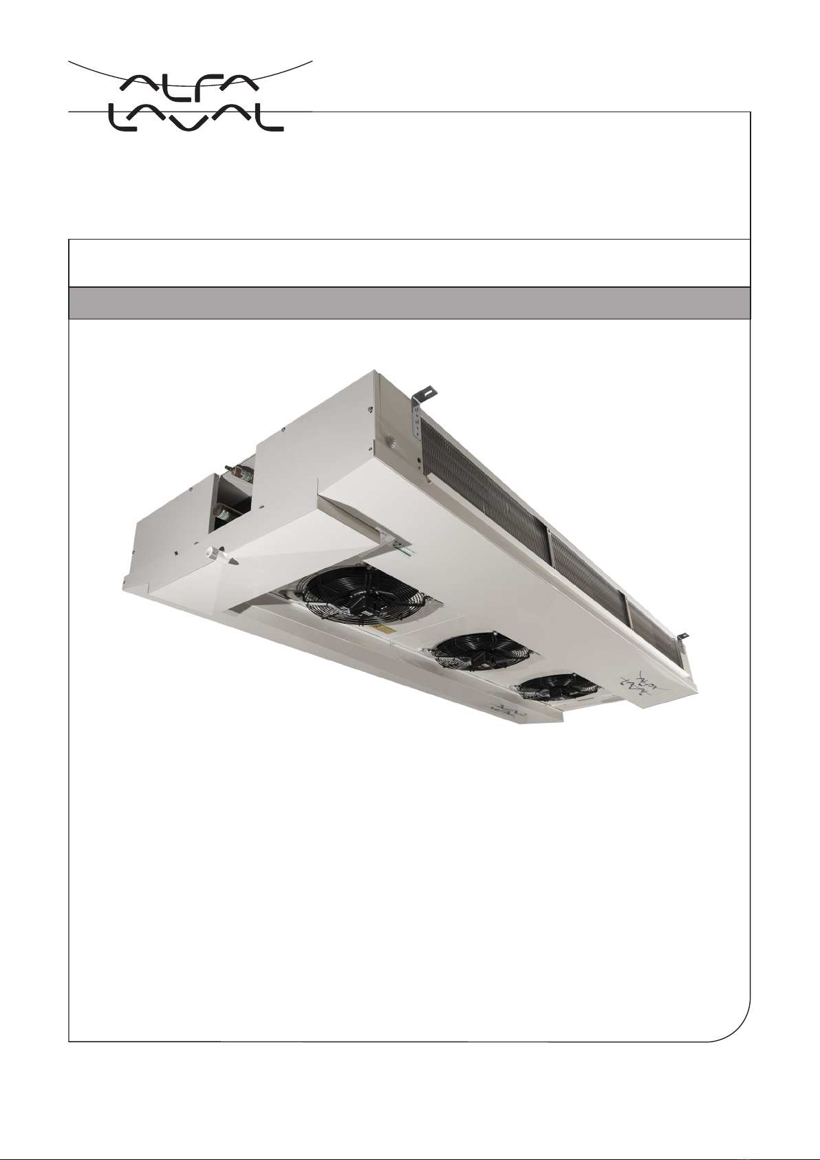
1 Commercial air cooler - dual discharge
2 Refrigerant system (E=HFO/HFC DX, W=brine, X=CO2 DX)
3 Fan speed (H=high speed, L=low fan speed)
4 Fan motor type (blank=AC, E=EC)
5 Fan diameter (30=300, 40=400 mm)
6 Number of fans (1 to 4)
7 Tube rows code (B, C)
8 CD version
9 No. of phases (S=1, T=3)
10 Motor voltage
11 Packing (BOP=box + pallet, CR=crate)
12 Casing material (PC=epoxy coated aluminium, SS=stainless steel)
13 Defrost system (A=air defrost, E=electric defrost)
14 Connection box (blank=without connection box, CB/CBM=with connection box)
15 Fin material (AL=aluminium, EP=epoxy coated aluminium, CA=cataphoresis)
16 Fin spacing (4, 5.5, 7, 10 mm)
17 Tube material (CU=copper)
18 Options

AHE00046EN 1904
6
Alfa Laval is a trademark registered and owned by Alfa Laval Corporate AB.
Alfa Laval reserves the right to change specification without prior notification.
3 Product labels
⑥⑦
①
⑨
⑩
⑧
③②
⑤④
WARNING
READ INSTRUCTION MANUAL BEFORE
INSTALLATIONS OPERATIONS AND MAINTENANCE
TO AVOID INJURIES OR DAMAGE
Country of origin Italy
Manufacturer: Manuf. Date:
AIR HEX ALONTE S.R.L. - Italy 04 / 2019
Model: O.A. 1106756
CDXLE302 CS 230V BOP SSA CBM
CA 4.0 CU
Item ID: 32892164042
Serial no. AP 5002763
Unit Net Weight: 37,800 Kg ±5%
Sn
Motorfan data:
Vn: 1~230V
f: 50/60 Hz
EXAMPLE
WARNING
READ INSTRUCTION MANUAL BEFORE
INSTALLATIONS OPERATIONS AND MAINTENANCE
TO AVOID INJURIES OR DAMAGE
Manufacturer: Manuf. Date:
AIR HEX ALONTE S.R.L. - Italy 04 / 2019
Model: O.A. 1106756
CDXLE302 CS 230V BOP SSA CBM
CA 4.0 CU
Item ID: 3289216404
Serial no. AP 5002763
Sn
Coil PED data: ART. 4.3
Max DN: 9 mm
Fluid Group 2
Coil Ts: +125/-60 °C
Ps: 80 bar
Pt: 114 bar
Test Date: 04-2019
EXAMPLE
1. Product label
Model Refer to paragraph "Code
description"
Item ID
Serial no.
Communicate these when
ordering spare parts as
they identify the unit.
O.A. Order Acknowledgement
number
Unit Net Weight Check before any lifting
operation to ensure that
proper lifting tools are used
2. Product label - coil
Model Refer to paragraph "Code
description"
Item ID
Serial no.
Communicate these when
ordering spare parts as
they identify the unit.
Max DN Maximum diameter of the
distributor tube
Fluid Group According to PED
Coil Ts Range of operating tem-
peratures for the coil
Ps Design pressure
Pt Test pressure
Test date Date on which the coil has
been pressure tested in
the factory

AHE00046EN 1904
7
Alfa Laval is a trademark registered and owned by Alfa Laval Corporate AB.
Alfa Laval reserves the right to change specification without prior notification.
5.307
ATTENZIONE!
CIRCUITO FRIGORIFERO PRECARICATO CON AZOTO
WARNING!
PRECHARGED REFRIGERANT CIRCUIT WITH NITROGEN
ACHTUNG!
VERLADTER KÄLTEMITTELKREISLAUF MIT STICKSTOFF
ATTENTION!
CIRCUIT FRIGORIFIQUE PRE-CHARGE AVEC AZOTE
BHИМАНИЕ!
СИСТЕМА ЗАПРАВЛНА АЗОТОМ
3. Nitrogen precharge warning
Units are delivered from the manufacturer
with an overpressure. Check pressure on
the Schrader valve. With unpressurised unit:
Immediate report to manufacturer and note on
bill of delivery.
6. Fan motor
Fan motor item number.
7. Electrical warning
Electrically powered component. Switch off
power supply before any maintenance or instal-
lation activity.
8. Fan direction
Sticker indicates fan rotation direction.
9. Moving parts
Warning: moving parts.
Switch off power supply before any maintenance
or installation activities.
PARTI INTERNE IN MOVIMENTO A
COMANDO AUTOMATICO.
TOGLIERE TENSIONE PRIMA DI TOCCARE
AUTOMATIC CONTROL MEANS MOVING
INTERNAL PARTS.
SWITCH OFF POWER BEFORE TOUCHING
SCHALTUNG AUF AUTOMATIK, INTERNE
BAUTEILE IN BETRIEB. VOR ARBEITSBEGINN
SPANNUNG UNTERBRECHEN
ÉLÉMENTS INTERNES A DÉMARRAGE
AUTOMATIQUE. COUPER L’ALIMENTATION
ÉLECTRIQUE AVANT INTERVENTION
Cod. 69100175
Spare part
item no
9460088799
IN
OUT
4/5. In/Out
Refrigerant connections inlet and outlet.
10. Eurovent
Sticker is applied when the product is included
in the Eurovent Certify All program.

AHE00046EN 1904
8
Alfa Laval is a trademark registered and owned by Alfa Laval Corporate AB.
Alfa Laval reserves the right to change specification without prior notification.
Always follow guidelines and instructions as given in the air cooler product manual AHE00042.
Optigo CD air coolers are delivered on a wooden pallet, either covered with a reinforced cardboard
box (CD300) or a wooden crate (CD400). Handling and positioning can take place manually (small-
er models) or with use of a forklift. Packed air coolers may be stacked during transportation and
storage.
Respect the maximum number of stacked air
cooler units.
4 Unpacking and lifting
>50 mm
Lift the unit to mounting position and secure
following instructions given in chapter "5
Installation". After having secured the cooler,
the forks may be lowered and the remaining
packaging materials can be removed (cardboard
CD300, crate for CD400).
max. 4
max. 2
In order to avoid damage to the air cooler or fall-
ing of the unit, ensure that the lifting forks cover
all beams from the lower support pallet.
CD400 models are supplied in mounting posi-
tion. Prior to lifting and mounting, the top crate
panel must be removed and the mounting
brackets must be turned 90° and fixed with the
supplied fixing materials.
The smaller CD300 models must be turned.
Place the unit on the ground and manually turn
the air cooler into mounting position on a second
wooden pallet. Keep the packaging material in
place to prevent the drip trays from damaging.
Remove the original support pallet (now on top)
and remove the cardboard top sheet. The cooler
is now ready to be lifted to mounting position.
CD300 only
Remove the plastic strips that secure the EC fan
unit during transport and handling. The air cooler
is now ready to be installed.
CD300 only

AHE00046EN 1904
9
Alfa Laval is a trademark registered and owned by Alfa Laval Corporate AB.
Alfa Laval reserves the right to change specification without prior notification.
L
M1
M
M1
H1
H2
5.1 Mounting dimensions
Detailed drawings showing all required mounting and refrigerant
connection dimensions are available for download on www.alfalaval.com.
Dimensional drawings
5 Installation
Always follow guidelines and instructions as given in the air cooler product manual AHE00042.
W
cooler
model
Dimensions (mm) Shipping
L W H1 H2 M M1
volume
m3
CD 301 949 1012 170 203 550 - 0.5
CD 302 1499 1012 170 203 1100 - 0.8
CD 303 2049 1012 170 203 1650 1.0
CD 304 2599 1012 170 203 2200 1100 1.5
CD 401 1121 1160 350 400 820 - 1.1
CD 402 1910 1160 350 400 1609 - 1.8
CD 403 2700 1160 350 400 2399 - 2.6
ø 1" G ext.
25 (CD300)
20 (CD400)
10 (CD300)
12 (CD400)

AHE00046EN 1904
10
Alfa Laval is a trademark registered and owned by Alfa Laval Corporate AB.
Alfa Laval reserves the right to change specification without prior notification.
5.2 Mounting bracket
Use extra wide washers (ISO 7093) when
mounting the unit to the ceiling.
5.3 Technical spaces
L
D
D≥L
Respect the required minimum space for defrost
heater replacement.
25
10
20
12
CD300 CD400
washers ISO-7093
Never bend the air cooler refrigerant connection
tubes.
The drain line diameter must be at least the size
of the driptray drain diameter and should be laid
with an adequate slope. For room temperatures
below 0° C drain line insulation and defrosting
are required.
A syphon must be installed on the drain line,
outside the cold room
5.5 Drain line
5.4 Refrigerant connections
Tighten drain connection by hand only.

AHE00046EN 1904
11
Alfa Laval is a trademark registered and owned by Alfa Laval Corporate AB.
Alfa Laval reserves the right to change specification without prior notification.
5.6 Electrical connections
The following data determine which connection diagram is to be selected
and respected for electrical installation:
• Heat exchanger model indication
• Fan motor type
• Electrical options
Detailed electrical connection diagrams are available for download on www.alfalaval.com.
When in doubt always contact your local supplier or Alfa Laval representative for assistance.
M
1
~
LN
PE
L
N
PE
-M
1
M
1
~
M
1
~
LN
PE
L
N
PE
-M
1
L
N
PE
-M2
M
1
~
M
1
~
M
1
~
LN
PE
L
N
PE
-M
1
L
N
PE
-M2
L
N
PE
-M3
M
1
~
M
1
~
M
1
~
M
1
~
LN
PE
L
N
PE
-M
1
L
N
PE
-M2
L
N
PE
-M3
L
N
PE
-M4
Electrical connections 1-4 fan motors 1 phase AC

AHE00046EN 1904
12
Alfa Laval is a trademark registered and owned by Alfa Laval Corporate AB.
Alfa Laval reserves the right to change specification without prior notification.
M
3
~
UV
W
U1 V1 W1 PE TK TK
-M
1
TK1
PE TK TK
M
3
~
UV
W
U1 V1 W1 PE TK TK
-M
1
TK1
PE TK1TK2
M
3
~
TK3
U1 V1 W1 PE TK
TK
-M2
TK2
M
3
~
UV
W
U1 V1 W1 PE TK TK
-M
1
TK1
PE TK1TK2
M
3
~
M
3
~
TK3
U1 V1 W1 PE TK TK
-M2
TK2
U1 V1 W1 PE TK
TK
-M3
TK3
TK4
M
3
~
M
3
~
M
3
~
M
3
~
UV
W
U1 V1 W1 PE TK TK
-M
1
TK1
PE TK1TK2
TK3
U1 V1 W1 PE TK TK
-M2
TK2
U1 V1 W1 PE TK TK
-M3
TK3
TK4TK5
U1 V1 W1 PE TK
TK
-M4
TK3
Electrical connections 1-4 fan motors 3 phase AC

AHE00046EN 1904
13
Alfa Laval is a trademark registered and owned by Alfa Laval Corporate AB.
Alfa Laval reserves the right to change specification without prior notification.
Fan speed selection
High/Low
Electrical connections 2-speed EC fan motors CD300
Electrical connections 2-speed EC fan motors CD400
M
1
~
M
1
~
M
1
~
L
N
PESN
-M1
L
N
PESN
-M2
L
N
PESN
-M3
LNLN
PE
PE
TK
TK
PE
TK
TK
PE
TK
TK
Put jumper for unit with L noise level

AHE00046EN 1904
14
Alfa Laval is a trademark registered and owned by Alfa Laval Corporate AB.
Alfa Laval reserves the right to change specification without prior notification.
Low speed connection
Connect blue wire to neutral (N) and black wire
to power supply (L).
Open the orange clamps from the blue and
brown wires.
Create a jumper connection between the brown
(SN) and the blue (N) wires. This extra piece of
cable is not supplied with the unit.
brown
blue
black
High speed connection
Connect blue wire (N) to neutral.
Connect black wire (L) to power supply.
black
blue
Open the connection box, located at the end
plate opposite the refrigerant connections.
You will find the electric wiring diagram inside
the connection box.
Speed selection

AHE00046EN 1904
15
Alfa Laval is a trademark registered and owned by Alfa Laval Corporate AB.
Alfa Laval reserves the right to change specification without prior notification.
L1
L2 L3 N
PE
PE
-R1
PE
-R4
PE
-R2
PE
-R5
PE
-R3
PE
-R6
L1 L2 L3
N
Incoming supply
400V - 50Hz 3phase+N
LN
PE
PE
-R7
PE
-R10
PE
-R8
PE
-R11
PE
-R9
PE
-R12
L
N
Incoming supply
230V - 50Hz 1phase
Electrical connections coil defrost heater elements CD400B (4+2 heaters)
Electrical connections driptray defrost heater elements CD300

AHE00046EN 1904
16
Alfa Laval is a trademark registered and owned by Alfa Laval Corporate AB.
Alfa Laval reserves the right to change specification without prior notification.
Coil defrost Driptray defrost
Model
Tube
rows
no.
heater
elements
no.
power
per
heater
W
total
power
W
heater
elements
no.
power
per heater
W
total
power
W
CD301 4/6 - - - 2 475 950
CD302 4/6 - - - 2 800 1600
CD303 4/6 - - - 2 1300 2600
CD304 4/6 - - - 2 1600 3200
CD401 B 4 4 500 2000 2 400 800
CD401 C 6 6 500 3000 2 400 800
CD402 B 4 4 1200 4800 2 800 1600
CD402 C 6 6 1200 7200 2 800 1600
CD403 B 4 4 1700 6800 2 1200 2400
CD403 C 6 6 1700 10200 2 1200 2400
5.7 Electric defrost capacities
UV
W
N
PE
PE
-R1
PE
-R4
PE
-R7
PE
-R2
PE
-R5
PE
-R8
PE
-R3
PE
-R6
Electrical connections coil defrost heater elements CD400C (6+2 heaters)

AHE00046EN 1904
17
Alfa Laval is a trademark registered and owned by Alfa Laval Corporate AB.
Alfa Laval reserves the right to change specification without prior notification.
6 Maintenance
Ensure complete electrical isolation before performing any maintenance activity and always follow
guidelines and instructions as given in the air cooler product manual AHE00042.
6.1 Fan replacement
Unscrew fixing bolts and remove old fan. Mount
new fan in identical position. Use an anti-corro-
sion compound when remounting the fixing bolts.
Restore electric connection when the new fan
has been mounted.
6.2 Driptray
Driptrays can be opened for inspection, cleaning
and maintenance purposes. To open the drip-
trays, the central connecting driptray needs to be
removed first. Disconnect drain line and remove
central driptray.
Not too tight!
When (re)mounting the primary driptrays, the
hinge fasteners should NOT be fully tightened,
to allow the driptray hinges to function properly.
To open both primary driptrays, first loosen and
remove fixing bolts and then lower the driptrays.
Respect the maximum opening angle (90°) to
avoid damage to the driptray hinges.

AHE00046EN 1904
18
Alfa Laval is a trademark registered and owned by Alfa Laval Corporate AB.
Alfa Laval reserves the right to change specification without prior notification.
Bend open
clips
Always disconnect power supply before handling
heater elements.
To remove coil heater elements, open side cov-
ers on both sides. Disconnect heater elements,
remove fixing screws and extract elements from
coil.
Mount new elements in reverse order, close side
covers and restore electrical connections.
6.5 Driptray heater elements replacement
Always disconnect power supply before handling
heater elements.
To remove driptray heater elements, remove
central driptray and open primary driptray.
Disconnect heater element and remove element
from bottom plate while slightly bending open
the fixing clips. Mount new element in reverse
order, close driptray, remount central driptray
and restore electrical connections.
6.4 Coil heater elements replacement
6.3 Side covers
All side covers can be opened for inspection,
cleaning and maintenance purposes. This can
be done only by qualified personnel. To open
side covers, loosen fixing bolts.

AHE00046EN 1904
19
Alfa Laval is a trademark registered and owned by Alfa Laval Corporate AB.
Alfa Laval reserves the right to change specification without prior notification.
Alfa Laval Anytime
Spare parts Optigo CD
1 Fan motors
2 Defrost heater kits (all heaters, conn. box & fixing materials)
3 Driptray left
4 Driptray right
5 Driptray central
Spare parts can be selected and ordered in the online eBusiness tool
Alfa Laval Anytime. If required please contact your local Alfa Laval
representative for assistance.
7 Spare parts
③
①
②
④
⑤

www.alfalaval.com
Table of contents
Other Alfalaval Heating System manuals
Popular Heating System manuals by other brands

Viessmann
Viessmann VITOCELL 100-W Installation and service instructions for contractors

Ferroli
Ferroli UT REC+ Installation, use and maintenance manual

Kabola
Kabola Ecoline series user manual

Immergas
Immergas HYDRO Instructions and warnings

Daikin
Daikin EAH04A6 installation manual

DMS
DMS FR Series manual

ITR
ITR Hurricane Zephyr HW Installation and operating manual

Broan
Broan ERV120T installation guide

Dimplex
Dimplex DuoHeat Duo300N operating instructions

Panasonic
Panasonic U-72MF1U9 Technical data

Nuaire Group
Nuaire Group MRXBOX90L Installation and Maintenance

Napoleon
Napoleon DYNAMIC HEAT CONTROL PLUS Series Installation and operation manual