Kemper FK-5 User manual

!
Operating instructions for FK-5
Break Tank Station
Fig. 369

2/56 – K410036900025-00 / 09.2023 – ©www.kemper-group.com
Table of contents Safety instructions
Important of the document
Read this manual before commissioning, use or maintenance, and
follow the instructions given!
Always pass these instructions on to current the device operating
organisation and retain for later reference!
Warnings
Be sure to read and follow the warnings in the manual. Disregard of
the warning information may lead to injury or material damage!
Labelling of important warning information:
Danger! Electricity!
Indicates hazards that might result in severe or fatal
injury.
Warning! Indicates hazards that may result in injury,
material damage or contamination of drinking water.
Note! Indicates hazards that may result in
damage to the system or malfunctions.
Disposal
Local regulations on waste recycling and disposal must be
followed.The product must not be disposed of with
household waste but must rather be disposed of appropriately.
Old batteries must not be disposed with household waste.
Consumers are obligated by law to take batteries to a
suitable trade or communal collection site. Handing these
batteries in is free of charge. You can also send your used
batteries back to us.
Use
The KEMPER FK-5 Break Tank Station is used for separating potable
from non-potable water installations if uid category 5 according to
DIN EN 1717 / DIN 1988-100.
The device must only be operated with water.
Do not ll with ammable or explosive media.
Warning! The product must only be used for this purpose as Break
Tank Station in enclosed, frost-free, dry rooms. Any other use is
considered contrary to the designated use.
Warning! Disregard of instructions during installation, use or main-
tenance can impair proper operation and can cause considerable
health problems due to the mixture of drinking and non-potable
water.
Do not install two or more Break Tank Stations parallel.
Ensure that you adhere to the specied maintenance intervals.
Malfunctions and errors must be rectied immediately by a specialist.
Safety instructions 2
Introduction | 0.1
Controller symbols
Program explanations 4
Main menu | 1.0
1.1 System settings 6
1.1.1 • Language 7
• Date
• Time
• Activate accessories
• Error signal
• Battery change
• Factory settings
1.2 Pump 8
1.3 Messages 12
1.4 Drain tank 13
1.5 Inlet control 17
Operating modes | 2.0
2.1 Select operating mode 18
2.1.1 Time program 19
2.2.1 Automatic program 24
Cleaning | 3.0
3.1 Flush inlet pipe 28
3.2 Clean tank 34
Process | 4.0
4.1 Verbrauchsdaten abrufen 40
USB menu | 5.0
5.1 Save system data 42
Updates | 6.0
6.1 Install updates 44
Battery change | 7.0 46
Messages | 8.0 52

© www.kemper-group.com – 09.2023 / K410036900025-00 – 3 /56
Safety instructions
Power supply 230 V AC
Electrical power input DN 20: 3,3 A
DN 25: 5,5 A
Electrical power DN 20: 759 W
DN 25 1265 W
Power factor 0,97
Protection class IP 54
Medium Water
Ambient temp., max. 40°C
Ambient temp., min. 2°C
Inowing medium, temp. max. 35°C
Inowing medium, temp. min. 2°C
Flow pressure, max. DN 20/DN 25: 4,0 bar | 0,4 MPa
Flow pressure, min. DN20: 1,0 bar | 0,1 MPa
DN25: 1,5 bar | 0,15 MPa
Pressure stage PN 10
Outlet pump pressure DN 20: 4.3 bar | 0,43 MPa
DN 25: 5,9 bar | 0,59 MPa
DU value DN 20: 0,83 l/s
DN 25: 1,67 l/s
Sanitary and drinking water installation:
DIN EN 1717 / DIN 1988-100
DIN EN 806-5
EMC:
EN 61000-6-1
EN 61000-6-3
Low-voltage:
EN 60335-1
Machinery Regulation:
(EU) 2023/1230
Use the device
- only in sound condition
- as intended.
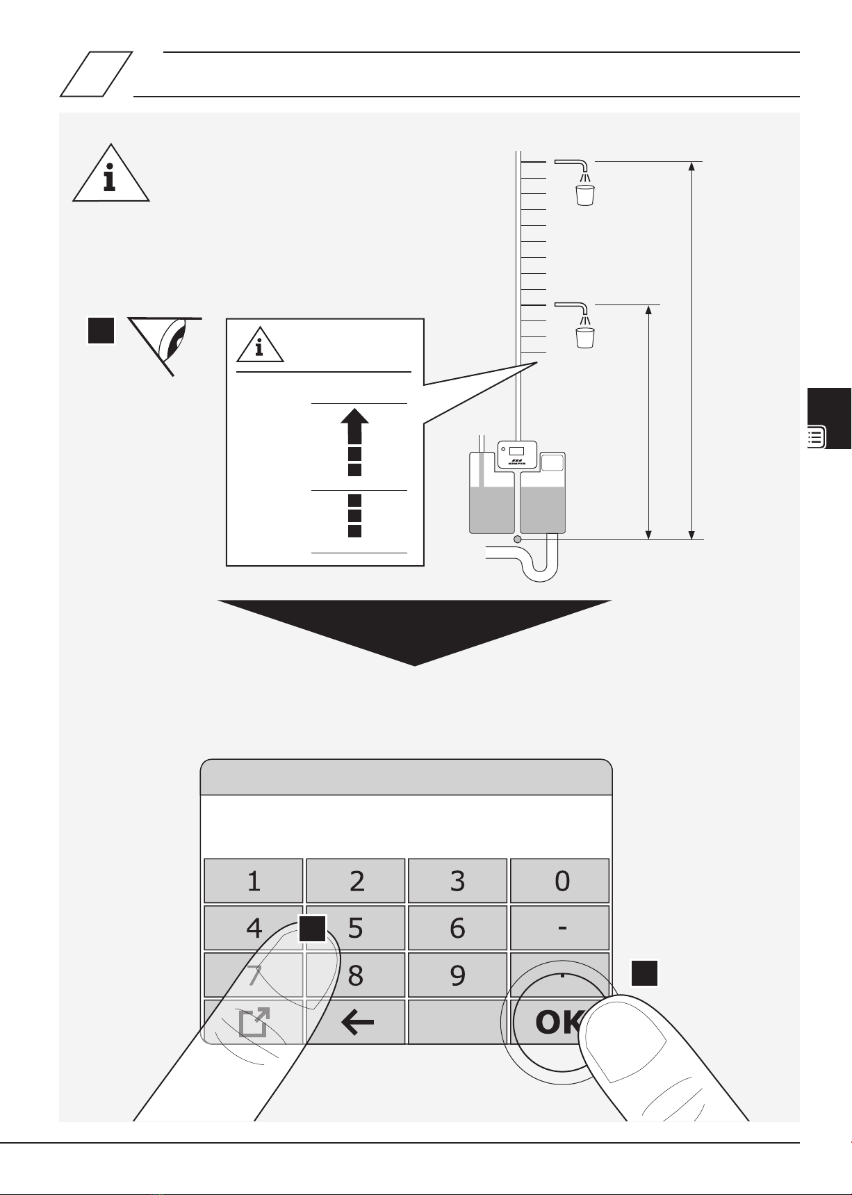
Note! A software update is recommended if the current version of
the rmware is not present.
Liability
No warranty or liability for:
- Non-compliance with the instructions.
- Incorrect installation and/or operation.
- Unauthorised modication of the product.
- Other incorrect operation.
Warning! Any water withdrawn must under no
circustances be used as drinking water – even in small
amounts!
Note! The inlet valves and pump switch on automatically
for a short period of time if the device has not been used
for more than 48 hours.
Note! Only use suitable cleaning agents that do not foam
according to DVGW W 291 / W 319.
After cleaning the device, you must remove any cleaning
agent residues from the system completely!
Maintenance and repair
Warning! Only competent specialists with drinking water
installation qualications are permitted to carry out repair
or maintenance work.
Danger! Only specialists with electrical system
qualications are permitted to carry out electrical
installation, repair or maintenance work!
Danger! Before working on live components, be
sure to disconnect the system from the power supply.
Danger! Prior to any maintenance work on electrical
elements, disconnect the system from the mains. To do
this, always disconnect the mains plug.
Warning! Following the installation, addition of accessories or
maintenance, all feed pipes must be ushed according to DIN EN
806-5 and VDI/DVGW (Association of German Engineers/German
association for gas and water) 6023.
Warning! Priority must be given to the national and regional stan-
dards and provisions on sanitary installations, electrical installations
and accident prevention.
Note! Only remove the USB stick once data transmission is comple-
te, or the controller may be damaged during a rmware update.
Important notes for the device operating organisation

4/56 – K410036900025-00 / 09.2023 – ©www.kemper-group.com
0.1
FK-5 | DN 25
Operating modes
Plant off
StandbyTime Mode
Automatic
EN
Operating modes
Flushing and cleaning program
Main menu
Process
Device off
Switches off the supply of the tapping point outlets and
ushing processes. The alarm output remains active. The
alarm state is still logged. Operating mode also permits
settings on the device.
Warning messages
Device remains switched on.
Error messages
Device automatically switches off.
EN
Time mode
Denes the weekly program with daily start and stop times.
The tapping point outlet supply is switched off between the
programmed times. Flushing and cleaning programs are still
carried out.
Standby
Switches off the tapping point outlet supply.
The programmed ushing processes are still carried out.
Automatic mode
Bypasses the “Time mode” weekly program.
Time limit
Switches temporarily to automatic mode until the preset
time has elapsed.
Back
Start screen
Active area

© www.kemper-group.com – 09.2023 / K410036900025-00 – 5 /56
0.1
Flush inlet 1
Set automatic Automatic flushing
Deactivate flushing Flush manually
Inlet control
Inlet 2Inlet 1
Automatic
Operating times
Monday Off 00:00 - 00:00
Tuesday Off 00:00 - 00:00
Wednesday Off 00:00 - 00:00
Thursday Off 00:00 - 00:00
Friday Off 00:00 - 00:00
Saturday Off 00:00 - 00:00
Sunday Off 00:00 - 00:00
EN
Set automatic
Automatic ushing
This is where you can program the weekly program for
ushing the feed pipes. Every weekday with a start time and
ush duration (max. 360 minutes). A ush duration may not
span multiple days. Only one inlet can be ushed at a time.
Deactivate ushing
Flush manually
Triggers a manual inlet ushing.„Deactivate ushing“ or
„Automatic ushing“ stops this function. „Flush manual-
ly“ automatically ends after 360 minutes and the device
switches back to the „Deactivate ushing“ or „Automatic
ushing“ function that was active before.
EN
Inlet 1/2
“Inlet 1” or “Inlet 2” sets the supply to exclusively through
the respective inlet. If the particular inlet quantity is insuf-
cient, a warning message appears and the tapping point
outlet supply is switched off.
Inlet 1+2
(Automatic inlet control)
“Inlet 1+2” gives priority to supply through
inlet 2. If the inlet quantity is insufcient,
inlet 1 opens in addition.
If the overall inlet quantity is insufcient,
a warning message appears and the tapping point outlet
supply is switched off.
up
down
left
right
Conrm entry

6/56 – K410036900025-00 / 09.2023 – ©www.kemper-group.com
1
1.1
FK-5 | DN 25
Main menu
1. System settings
2. Pump
3. Messages
4. Empty tank
5. Inlet control

© www.kemper-group.com – 09.2023 / K410036900025-00 – 7 /56
1.1.1
System settings
1. Language Englisch
2. Date 23.07.2016
3. Time 11:07:48
4. Time change Auto On
5. Water supply set plus Off
6. Container cleaning set Off
1. Language English
2. Date 23.07.2016
3. Time 11:07:48
4. Time change Auto On
5. Water supply set plus Off
6. Container cleaning set Off
7. Overow monitoring Off
8. Key press signal On
9. Error signal On
10. Battery change
11. Factory menu
12. Factory settings

8/56 – K410036900025-00 / 09.2023 – ©www.kemper-group.com
Pump
1. Cut-in pressure 2.0 bar
2. Set
3. Relay cycles 0
Main menu
1. System settings
2. Pump
3. Messages
4. Empty tank
5. Inlet control
1.
2.
Betriebszeiten
Preset ex factory.
1.2
1.2.1

© www.kemper-group.com – 09.2023 / K410036900025-00 – 9 /56
Cut-in pressure
Min: 0.3-Actual: 2.0bar - Max: 6.0 bar
2.
3.
1.
20 m = 2.3 bar
max. 60 m = 6.3 bar
+10 m = +1 bar
20 m 2.3 bar
60 m 6.3 bar
0 m 0.3 bar
1.2.2

10/56 – K410036900025-00 / 09.2023 – ©www.kemper-group.com
Reset the counter
Reset
the counter?
Pump
1. Cut-in pressure 2.0 bar
2. Set
3. Relay cycles 0
1.2.3
1.2.4

© www.kemper-group.com – 09.2023 / K410036900025-00 – 11 /56
Reset the counter
Counter deleted!
1.2.5

12/56 – K410036900025-00 / 09.2023 – ©www.kemper-group.com
Messages
25.04.2016 12:16:45 [0019]
Error temperature measurement
out of range
29.04.2016 15:03:57 [0015]
Level below measuring range
Pump pressure
Main menu
1. System settings
2. Pump
3. Messages
4. Empty tank
5. Inlet control
1.
2.
Betriebszeiten
Error code [0001] - [0025].
8.0
1.3
1.3.1

© www.kemper-group.com – 09.2023 / K410036900025-00 – 13 /56
Main menu
1. System settings
2. Pump
3. Messages
4. Empty tank
5. Inlet control
1.
2.
Empty tank
Inlets closed
Solenoid valve On/Off
Pump controller On
Stop
Main menu
1. System settings
2. Pump
3. Messages
4. Empty tank
5. Inlet control
1.4
1.4.1

14/56 – K410036900025-00 / 09.2023 – ©www.kemper-group.com
KEMPER
Fig. 369 02
1.4.2 A

© www.kemper-group.com – 09.2023 / K410036900025-00 – 15 /56
Auto
Start
1.
1.4.2 B

16/56 – K410036900025-00 / 09.2023 – ©www.kemper-group.com
i
i
1.
3.
2.
Auto
OFF5 cm
G 3/4 "
1.4.3
1.4.4
B
B

© www.kemper-group.com – 09.2023 / K410036900025-00 – 17 /56
Inlet control
Inlet 2Inlet 1
Automatic
1.
2.
Main menu
1. System settings
2. Pump
3. Messages
4. Empty tank
5. Inlet control
1.
2.
Only if “Water supply set plus” is active.
1.5
1.5.1

18/56 – K410036900025-00 / 09.2023 – ©www.kemper-group.com
FK-5 UK | DN 25
Operating modes
Plant off
Standby
Automatic
Time Mode
2
2.1

© www.kemper-group.com – 09.2023 / K410036900025-00 – 19 /56
Time Mode
SettingsTime Mode On
Operating times
Monday Off 00:00 - 00:00
Tuesday Off 00:00 - 00:00
Wednesday Off 00:00 - 00:00
Thursday Off 00:00 - 00:00
Friday Off 00:00 - 00:00
Saturday Off 00:00 - 00:00
Sunday Off 00:00 - 00:00
2.1.1
2.1.2

20/56 – K410036900025-00 / 09.2023 – ©www.kemper-group.com
Operating times
Monday Off 00:00 - 00:00
Tuesday Off 00:00 - 00:00
Wednesday Off 00:00 - 00:00
Thursday Off 00:00 - 00:00
Friday Off 00:00 - 00:00
Saturday Off 00:00 - 00:00
Sunday Off 00:00 - 00:00
Operating times
Monday Off 00:00 - 00:00
Tuesday Off 00:00 - 00:00
Wednesday Off 00:00 - 00:00
Thursday Off 00:00 - 00:00
Friday Off 00:00 - 00:00
Saturday Off 00:00 - 00:00
Sunday Off 00:00 - 00:00
2.1.3
2.1.4
Other manuals for FK-5
11
Table of contents
Other Kemper Safety Equipment manuals