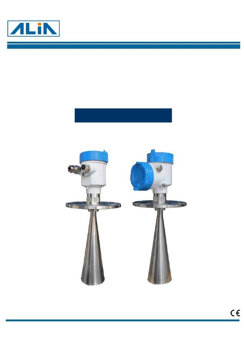
Alia ADP9000 Series User manual

ADP9000 Operation Manual OPADP9000.1.1.5.R1ENG
1
Differential Pressure Transmitter
Model ADP9000 Series
Operation Manual
Alia Group Inc. URL : http://www.alia-inc.com
TEL : +1 - 302 - 213 - 0106 FAX : +1 - 302 - 213 - 0107 OPADP9000.1.1.5.R1ENG
ALIADP
®

ADP9000 Operation Manual OPADP9000.1.1.5.R1ENG
2
Index
1. Summary - - - - - - - - - - - - - - - - - - - - - - - - - - - - - - - - - - - - - - - - - - - - - - - - - - - - - - - - - - - - - - 3
1.1 Intruduction- - - - - - - - -- - - - - - - - - - - - - - - - - - - - - - - - - - - - - - - - - - - - - - - - - - - - - - - - - - 3
1.2 Characteristic- - - - - - - - - - - - - - - - - - - - - - - - - - - - - - - - - - - - - - - - - - - - - - - - - - - - - - - - - 3
2. Principle and wiring diagram- - - - - - - - - - - - - - - - - - - - - - - - - - - - - - - - - - - - - - - - - - - - - - - - -3
2.1 Principle - - - - - - - - - - - - - - - - - - - - - - - - - - - - - - - - - - - - - - - - - - - - - - - - - - - - - - - - - - - - 3
2.2 Dimensional Drawings- - - - - - - - - - - - - - - -- - - - - - - - - - - - - - - - - - - - - - - - - - - - - - - - - - - 4
2.3 Wiring - - - - - - - - - - - - - - - - - - - - - - - - - - - - - - - - - - - - - - - - - - - - - - - - - - - - - - - - - - - - - - 4
2.4 The function of keypad - - - - - - - - - - - - - - - - - - - - - - - - - - - - - - - - - - - - - - - - - - - - - - - - - - 5
2.5 Display - - - - - - - - - - - - - - - - - - - - - - - - - - - - - - - - - - - - - - - - - - - - - - - - - - - - - - - - - - - - - 5
3. How to set Zero Elecation, Zero Supression- - - - - - - - - - - - - - - - - - - - - - - - - - - - - - - - - - - - - - 6
3.1 Zero Supression- - - - - - - - - - - - - - - - - - - - - - - - - - - - - - - - - - - - - - - - - - - - - - - - - - - - - - -6
3.2 Zero Elevation - - - - - - - - - - - - - - - - - - - - - - - - - - - - - - - - - - - - - - - - - - - - - - - - - - - - - - -6
4. Parameter setting - - - - - - - - - - - - - - - - - - - - - - - - - - - - - - - - - - - - - - - - - - - - - - - - - - - - - - - - 7
4.1 Operate flow chart - - - - - - - - - - - - - - - - - - - - - - - - - - - - - - - - - - - - - - - - - - - - - - - - - - - - -7
4.2 User operate decription- - - - - - - - - - - - - - - - - - - - - - - - - - - - - - - - - - - - - - - - - - - - - - - - - - 8
4.3 Other function - - - - - - - - - - - - - - - - - - - - - - - - - - - - - - - - - - - - - - - - - - - - - - - - - - - - - - - - 9
4.4 How to set decimal point and minus- - - - - - - - - - - - - - - - - - - - - - - - - - - - - - - - - - - - - - - - - 10
4.5 How to set the engineering unit for display & output - - - - - - - - - - - - - - - - - - - - - - - - - - - - - 11

ADP9000 Operation Manual OPADP9000.1.1.5.R1ENG
3
1.Summary
1.1 Introduction
ADP9000 series Differential pressure transmitter is a type of intelligent multi-functional digital instruament, it’s
elaborate designed on the basis of mature and reliable transmitter technology, combined with advanced Single-chip
technology and smart digital transmitter technology.
The centerpiece of the Smart Differential pressure transmitter adopt16 bit Single-chip whose powerful and
high-speed calculate power guarantee the quality of the transmitter. The whole design focus on reliably, stability,
high-precision and intelligent.It also meets the requirements of industrial application.Hence,this software adopt digital
signal processing technology,has excellent anti-interference ability, zero point stability, Zero Sensitive Capability (ZSC)
and Temperature Sensitive Capability (TSC).
1.2 Characteristic
ADP9000 not only has excellent anti-interference ability, zero point stability, Zero Sensitive Capability(ZSC)and
Temperature Sensitive Capability(TSC),but also has many other merits as follow
Adopt S-PORT communication port; communicate with computer directly through special swift module.By the use of
special RS485 module could achieve far spread of digital signal or the constructed of RS485 industrial Wireless LAN.
Optional HART modules, has HEAT communication capabilities.
2. Principle and wiring diagram
2.1 Principle
When the Pressure or Differential pressure was input from external, the Capacitance value of the Sensor will be firstly
changed,and then switched by the digit signal into frequency and transfered to CPU,After computing by the CPU,a
linear output signal will be sent to mA control loop and flow out in the form of 4~20mA and display at last.
2.2 Dimensional Drawings
T/T
A
/D
‧Linear
‧Range
CPU
Current loop
Communication
HART
Display
Setting Keys
4~20mA

ADP9000 Operation Manual OPADP9000.1.1.5.R1ENG
4
2.2 Dimensional Drawings
2.3 Wiring
13 18 23 33 38
0
250
500
750
1000
Power Supply (VDC)
1250
S
Z
-
+
+
-
+
TEST
mA
-
-
+
13~38VDC
DG
8.8
92mm
130mm
104mm 110mm
S
Z
ESC ESC
ADP9000
PV Kpa
0.0
050 100%
L
54mm
60mm
188mm
DG
8.8
DG
8.8
DG
8.8
H

ADP9000 Operation Manual OPADP9000.1.1.5.R1ENG
5
2.4 The function of keypad
Key name Button Sign Parameter Setting Status Function
ESCAPE
ESC
Return to the former position
SET
SET
Enter in the Parameter setting, Save the Datas, Get to next step
MOVE
<
Move the cursor to the left
DOWN Reduce the values
UP Increase the values
1. Press and hold the
SET
button for about 3 seconds then release to enter the main menu settings. If there is no related
operation for 2 minutes in the setup menu, it returns to the normal display automatically.
2. Press and hold the button for about 3 seconds, release, then the LCD appears”GOOD”, the zero calibration was
finished.
3. After entering the password 040821 in sub 6, press and hold the button for about 3 seconds then release it to finish
Span Shift Setting
Under the condition of standard pressure source, add pressure to the standard value then press and hold the button
about 3 seconds, release it to finish Span Shift Setting
4. Press and hold both the +buttons for 3seconds to restore. It will back to the original condition as you never
enter the password.
2.5 Display
Code Code Function
SV Setting status
PV Measure status
ER Signal error or over pressure
mA, %, ,˚C ,Kpa, Mpa Display unit & Output
100%
50
0
Kpa
PV
100%
50
0
Kpa
PV
SETESC
ADP9000
SV Er mA Mpa
°C
%

ADP9000 Operation Manual OPADP9000.1.1.5.R1ENG
6
3. How to set Zero Elevation,Zero Supression
3.1 Zero Supression
When the meter is installed below the minimum level, Zero Superssion is used as follow:
3.2 Zero Elevation
DG
8.8
DG
8.8
DG
8.8
DG
8.8
316
316
ZS
100%500
Kpa
PV
100%500
Kpa
PV
SETESC
ADP9000
Low Level
High Level
H2
H1
DG
8.8
DG
8.8
DG
8.8
DG
8.8
316
316
Z
S
100%
500
Kpa
PV
100%
500
Kpa
PV
SE TES C
ADP9000
Low Level
High Level
H2
H1
Example:
H1=1000 mmH2O
H2=5000 mmH2O
SG=0.9
Then H1=1000*0.9=900 mmH2O
H2=5000*0.9=4500 mmH2O
Range = -900 ~ 4500 mmH2O
= -8.823 ~ 44.12 Kpa
Example:
H1=1000 mmH2O
H2=5000 mmH2O
SG=0.9
Then H1=1000*0.9=900 mmH2O
H2=5000*0.9=4500 mmH2O
Range High=H1+H2=5400 mmH2O
Range = 900 ~ 5400 mmH2O
= 8.823 ~ 52.94 Kpa

ADP9000 Operation Manual OPADP9000.1.1.5.R1ENG
7
4. Parameter setting
4.1 Operate flow chart
SET
/
SET ESC
SET
/
SET ESC
SET
/
SET ESC
SET
/
SET ESC
SET
/
SET ESC
SET
/
SET ESC
SET
/
SET ESC
SET
/
SET ESC
SET
/
SET ESC
SET
/
SET ESC
SET
/
SET ESC
SET
/
SET ESC
ESCESC
ESC
ESCESC
ESCESC
ESCESC
ESCESC
ESCESC

ADP9000 Operation Manual OPADP9000.1.1.5.R1ENG
8
4.2 User operate description
Span Setting (20 mA) ( Sub 2 )
Press
SET
to enter, then Press or to change the values.
Press
SET
to confirm, press
ESC
to cancel.
High-Low position setting (Sub 3 )
H – L * Can not be set by users
Communication Address (Sub 4 )
Press
SET
to enter, then Press or to change the values.
Press
SET
to confirm, press
ESC
to cancel.
Range: 0~250
Advance setting possword(Sub 6 )
Press
SET
to enter, then Press or to change the values.
Press
SET
to confirm, press
ESC
to cancel.
Notes: after entering the password, it’ll extend to14 submenus, while
SUB 7- SUB13 could not be altered for which are engineering function
Damping (Sub 5 )
Press
SET
to enter, then Press or to change the values.
Press
SET
to confirm, press
ESC
to cancel.
Range: 0~32 Seconds
Display Unit and Output Setting ( Sub 0 )
Press
SET
to enter, then Press or to select units.
Kpa Mpa mA % mA ˚C
Press
SET
to confirm, press
ESC
to cancel.
Zero Setting (4 mA)(Sub 1 )
Press
SET
to enter,then Press or to change the values
Press
SET
to confirm, press
ESC
to cancel.
Notes: Settings should not exceed the maximum range
Normal Display
Press and hold the
SET
for 3 seconds,then release it to enter the
parameter setting menu
SV
050 100%
00000.0
SV
HL
050 100%
000000
SV
050 100%
00000.0
SV
050 100%
050 100%
SET
SET ESC
SV
SV
SET
SET ESC
SV
SET
SET ESC
SV
SET
SET ESC
SV
SET
SET ESC
PV
Kpa
0.0
050 100%
SV
00000.0
050 100%
SET
SET ESC
SET
SET ESC
SET
SV
SV
000000
SV
050 100%
KPa
KPa
KPa
SV
00000.0
050 100%
KPa

ADP9000 Operation Manual OPADP9000.1.1.5.R1ENG
9
4.3 Other function
Enter manu SUb 6 and input the password.
Password : 040821 ( SUb 6 )
Cancel the Span shift setting and restore to the original condition.
Please enter the password: 040821
Password : 050728 ( SUb 6 )
Cancel the zero calibration setting and restore to the original condition.
Please enter the password: 040821
Press
SET
to enter the operating interface.
Press or to change the values. Set the values to SUb6 to enter
the parameter-setting menu of password management.
Normal Display
Press
SET
for 3 seconds then release it to enter the parameter-setting
menu.
Press or to change the values, use
<
button to move the
position of the cursor.Press
SET
to confirm.
000000
SV
050 100%
PV
Kpa
0.0
050 100%
SET
SET
SV
SV
050728
SV
050 100%
040821
SV
050 100%
SET

ADP9000 Operation Manual OPADP9000.1.1.5.R1ENG
10
4.4 How to set Decimal point and minus
Example: zero = - 5Kpa
Zero Setting (4 mA) ( Sub 1 )
Press
<
for three times to move the position of decimal point. as follow
Engineering Unit Setting ( Sub 0 )
Press
SET
to enter,then press or to select units: Kpa
Kpa Mpa mA % mA ˚C
Press
SET
to confirm
Zero Setting (4 mA) ( Sub 1 )
Press to change the values, press
SET
to confirm,
Then enter into Zero Setting
Press
SET
button for 3seconds then release to enter parameter-setting
menu.
Zero Setting (4 mA) ( Sub 1 )
Press or to change the values.set the values to 05 as follow.
Zero Setting (4 mA) ( Sub 1 )
Press
<
to move the position of decimal point, please press
<
for
once to move the decimal to the first place as follow.
Zero Setting (4 mA) ( Sub 1 )
Press or to change the values to “-“,
only the first value could be changed to “-”
PV
Kpa
0.0
050 100%
SV
00000.0
050 100%
SET
SET
SV
SV
SV
00 0000.
050 100%
SV
05 0000.
050 100%
SV
0.50000
050 100%
SV
-.50000
050 100%
SV
-.50000
050 100%
Zero Setting (4 mA) ( Sub 1 )
Press
<
for five times to move decimal points to the position as follow,
Zero Setting (4 mA) ( Sub 1 )
press
SET
to confirm,

ADP9000 Operation Manual OPADP9000.1.1.5.R1ENG
11
4.5 How to set the Engineering Unit for display & output
Example 1: Display in %, Output 4~20mA
1. Press
SET
button for 3seconds then release,it will go to Sub 0 ,press
SET
Buttom.
2. Press or until the display show mA, press
SET
go back to Sub 0 (setting output is mA)
3.Press
SET
again, Click or until the display show %, press press
SET
go back to Sub 0
4.Press
ESC
go back to normal display, now you can see the % and both show on the diplay, means the output
is 4~20 mA, display engineer unit is %.
Example 2: Display in Mpa, Output 4~20mAlinear
1. Press
SET
button for 3seconds then release, it will go to Sub 0 , press
SET
Buttom.
2. Press or until the display show mA, press
SET
go back to Sub 0 (setting output is mA linear)
3.Press
SET
again, Click or until the display show Mpa, press
SET
go back to Sub 0
4.Press
ESC
go back to normal display, now you can see the Mpa show on the diplay, means the output is
4~20 mA linear, display engineer unit is Mpa.
Example 3: Display in mA, Output 4~20mA
1. Press
SET
button for 3seconds then release,it will go to Sub 0, press
SET
Buttom.
2. Press or until the display show mA, press
SET
go back to Sub 0 (setting output is mA)
3.Press
ESC
go back to normal display, now you can see the and mA both show on the diplay, means the
output is 4~20 mA, display engineer unit is mA.
Example 4: Display in mA, Output 4~20mA linear
1. Press
SET
button for 3seconds then release,it will go to Sub 0, press
SET
Buttom.
2. Press or until the display show mA, press
SET
go back to Sub 0 (setting output is mA linear)
3.Press
ESC
go back to normal display, now you can see the mA show on the diplay, means the output is
4~20 mA linear, display engineer unit is mA.
Table of contents
Other Alia Transmitter manuals