manuals.online logo
Brands
  1. Home
  2. •
  3. Brands
  4. •
  5. ALIBI
  6. •
  7. Security Camera
  8. •
  9. ALIBI ALI-BC1720PVF HD-TVI User manual

ALIBI ALI-BC1720PVF HD-TVI User manual

Other ALIBI Security Camera manuals

ALIBI ALI-CD1080PV User manual

ALIBI

ALIBI ALI-CD1080PV User manual

ALIBI ALI-TS2118VR User manual

ALIBI

ALIBI ALI-TS2118VR User manual

ALIBI ALI-TS4115R User manual

ALIBI

ALIBI ALI-TS4115R User manual

ALIBI ALI-TS4112R User manual

ALIBI

ALIBI ALI-TS4112R User manual

ALIBI ALI-CS1080P User manual

ALIBI

ALIBI ALI-CS1080P User manual

ALIBI ALI-IPU3130R User manual

ALIBI

ALIBI ALI-IPU3130R User manual

ALIBI ALI-NS1012VRP User manual

ALIBI

ALIBI ALI-NS1012VRP User manual

ALIBI ALI-NS2004R User manual

ALIBI

ALIBI ALI-NS2004R User manual

ALIBI ALI-CD1720EC User manual

ALIBI

ALIBI ALI-CD1720EC User manual

ALIBI ALI-NS4114R User manual

ALIBI

ALIBI ALI-NS4114R User manual

ALIBI ALI-NS4002R User manual

ALIBI

ALIBI ALI-NS4002R User manual

ALIBI ALI-NS4012R User manual

ALIBI

ALIBI ALI-NS4012R User manual

ALIBI ALI-NP1018VHP Operator's manual

ALIBI

ALIBI ALI-NP1018VHP Operator's manual

ALIBI ALI-NS1024VR User manual

ALIBI

ALIBI ALI-NS1024VR User manual

ALIBI ALI-NS8024VR User manual

ALIBI

ALIBI ALI-NS8024VR User manual

ALIBI ALI-NS4022R User manual

ALIBI

ALIBI ALI-NS4022R User manual

ALIBI ALI-TS2025R User manual

ALIBI

ALIBI ALI-TS2025R User manual

ALIBI ALI-TS7012V User manual

ALIBI

ALIBI ALI-TS7012V User manual

ALIBI ALI-TP4013R 3MP HD-TVI 260' IR User manual

ALIBI

ALIBI ALI-TP4013R 3MP HD-TVI 260' IR User manual

ALIBI ALI-TP2118VR User manual

ALIBI

ALIBI ALI-TP2118VR User manual

ALIBI ALI-NP3016RH User manual

ALIBI

ALIBI ALI-NP3016RH User manual

ALIBI ALI-CD1080PI User manual

ALIBI

ALIBI ALI-CD1080PI User manual

ALIBI ALI-TS3025R User manual

ALIBI

ALIBI ALI-TS3025R User manual

ALIBI ALI-NP7012RT User manual

ALIBI

ALIBI ALI-NP7012RT User manual

Popular Security Camera manuals by other brands

Okina USA SIR36-870VF650LP user manual

Okina USA

Okina USA SIR36-870VF650LP user manual

Divio NDR155PA user manual

Divio

Divio NDR155PA user manual

Easy Access EasyGuard user manual

Easy Access

Easy Access EasyGuard user manual

Vivotek FD9389-EHV-v2 Quick installation guide

Vivotek

Vivotek FD9389-EHV-v2 Quick installation guide

TUYA COSMO W2 manual

TUYA

TUYA COSMO W2 manual

Eusso UNC7500-IR Advanced installation guide

Eusso

Eusso UNC7500-IR Advanced installation guide

urmet domus 1096/204 user manual

urmet domus

urmet domus 1096/204 user manual

VC VC20 series operating manual

VC

VC VC20 series operating manual

Axis Q1614 installation guide

Axis

Axis Q1614 installation guide

ieGeek DD201 manual

ieGeek

ieGeek DD201 manual

VADDIO ClearVIEW HD-USB PTZ 999-6990-000 Installation and user guide

VADDIO

VADDIO ClearVIEW HD-USB PTZ 999-6990-000 Installation and user guide

Vicon V662-D-1 Installation and operation guide

Vicon

Vicon V662-D-1 Installation and operation guide

Grundig GCH-K0274P owner's manual

Grundig

Grundig GCH-K0274P owner's manual

Lorex VANTAGE LBC7032 quick start guide

Lorex

Lorex VANTAGE LBC7032 quick start guide

4xem WPT Specifications

4xem

4xem WPT Specifications

Samsung SCV-3082 Specifications

Samsung

Samsung SCV-3082 Specifications

Vitek VTC-C544 Specifications

Vitek

Vitek VTC-C544 Specifications

Lumens VC-A50PNW installation guide

Lumens

Lumens VC-A50PNW installation guide

manuals.online logo
manuals.online logoBrands
  • About & Mission
  • Contact us
  • Privacy Policy
  • Terms and Conditions

Copyright 2025 Manuals.Online. All Rights Reserved.

1www.observint.com ALI-BC1720P_CQ
9/24/14
TOOLS YOU NEED
To install the camera, you will need:
• 12 Vdc power source. See Specications for wattage requirement.
• Tools and additional fasteners (may be required) for mounting the camera
• Phillips #2 screwdriver
• Video and power extension cables
• CCTV video setup monitor (optional)
INSTALLATION
Before installation:
• Make sure that the device is in good condition and all the assembly parts are included.
• Check the specication of the products for the installation environment.
• Make sure that the wall or the ceiling is strong enough to withstand 3 times the weight of the camera.
• To avoid re or shock hazard, use only UL listed power supplies. Verify that the power supply will
provide the rated voltage and wattage for the camera. See the Specications section.
During installation:
• Camera Lens: Handle the camera carefully to prevent scratching or soiling the lens. If the lens or IR
array shield becomes soiled, clean it only with approved products. See the Cleaning section.
• Monitor impedance: Set the monitor impedance switch to 75 Ω.
• Power supply: Camera drop cable: The camera drop cable includes two connectors:
—Video BNC connector: For transmission of the video signal across a coax (75 Ω) extension cable.
—Power connector: When applying Vdc power, observe the power polarity. See the picture to the
right for the connector polarity conguration.
Mounting the camera
These cameras can be mounted on a wall or ceiling that has sucient strength to support it. The video/
power drop cable from the camera can be routed either through mounting surface or through a cable guide
on the edge of the mounting base.
Typical ceiling mounting
NOTE
If mounting the camera on a wall, ensure that the label on the mounting base, “Bottom,” is down.
If mounting the camera on a ceiling, orient the mounting base so that the cable guide is pointing
away from any source of water, dust, and other contaminates.
1. Using the drill template provided, mark the location of the screws that anchor the mounting base
to the mounting surface. See the note above. If you are routing the drop cable through mounting
surface, also mark the position of the hole for the drop cable.
2. Drill holes for the screws that anchor the base to the mounting surface. The mounting hardware
provided is appropriate for most surfaces. However, depending on the surface materials, more
appropriate fasteners may be required.
3. Drill a 3/4” hole through the mounting surface for the drop cable, if necessary.
4. Route the drop cable through the hole in the mounting surface, or through the cable guide in the
mounting base, then attach the camera assembly to the surface using the appropriate fasteners.
5. Connect the camera drop cable to video and power extension cables as required. NOTE: The
camera includes both an HD-TVI and CVBS video drop cables.
6. Connect the other end of the video extension cable to a video monitoring device, such as a CCTV
system monitor or HD-TVI compatible DVR.

NOTE Drop cable connectors are not waterproof.
ALI-BC1720PVF HD-TVI Outdoor
Infrared Bullet Camera
Quick Installation and User Guide
The ALI-BC1720PVF camera feature a 1/3” CMOS image sensor that delivers HD-TVI high-denition video
resolution over RG59 coax or any standard analog CCTV cabling. These HD video camera is ideal for security
applications that require a high level of detail, such as facial recognition or license plate identication.
Features
• CMOS image sensor
• HD-TVI technology produces 720p HD video for sharp, detailed images
• 2.8 - 12 mm vari-focal lens with viewing angle of 78° ~ 28°
• Built-in IR LEDs enables the camera to see up to 131 feet in the dark
• Smart IR technology reduces over-exposure of the IR LEDs at the center of the image
• True day/night (ICR) captures sharp, clear images in low light and at night
• OSD (On-Screen Display) controls for customizing the camera settings for the installation venue
• -4 °F ~ 140 °F temperature operating range
• IP66 weather-rated housing
Camera body
OSD Controller Lens Adjustments
Mounting
base Sun shield
Drop Cable
Cable Channel
Lens
IR LED
Array
Adjustable
mounting
bracket
ALI-BC1720PVF camera
Power
Connector
HD-TVI video BNC
Connector
CVBS video BNC
Connector
ALI-BC1720PVF Camera drop cable connectors
What’s in the box
• Camera assembly
• Mounting hardware
• Video test cable
• Drill template
• This installation guide
Video test cable
2www.observint.com
7. Connect the other end of the power extension cable to a 12 Vdc power source. Observe the polarity
of the cable shown in the photo on page 1 of this guide.
Camera adjustments
8. Apply power to the camera.
9. Verify that video from the camera can be seen on a monitor. NOTE: Video from the CVBS drop able
or the video test cable is NTSC video and can be displayed on most NTSC compatible monitors.
Video from the HD-TVI drop cable must be connected to an HD-TVI compatible video recorder (DVR)
system.
10. While observing video from the camera, loosen the mounting bracket pan, elevation and horizontal
line adjustment lock screws, point the camera at your surveillance target, and then tighten
adjustment lock screws or nuts to hold the camera in position.
The mounting bracket pan adjustment can be made after loosening the lock nut (see the photo
below).
0° ~ 90°
0° ~ 360°
0° ~ 360°
Use for horizon line
adjustment
Use for pan
adjustment
(lock nut)
Use for
elevation
adjustment
Camera mounting bracket adjustment
11. Remove the cover on the underside of the camera to access the Far - Near and Tele - Wide
adjustments.
0° ~ 360°
Rotate
CCW to
remove
cover
OSD
joystick
and CVBS
switch
Tele (T) -
Wide (W)
adjust
Far (F) -
Near (N)
adjust
Slide
forward
and lift
to remove
cover
tool
Underside of camera body
12. Using the cover you removed as a tool, turn the Far - Near and Tele - Wide adjustment screws to
produce the best image.
13. Reinstall the Far - Near and Tele - Wide adjust cover.
USING THE OSD
Use the OSD to adjust the internal settings of the camera to customize it for the installation venue.
1. Remove the cover on the underside of the camera to access OSD joystick and HD-TVI/CVBS switch.
See the photos above.
OSD
joystick
p
q
t u
Plug for
video test
cable
joystick
HD-TVI / CVBS
output switch
The OSD joystick is used to open the OSD menu and navigate through the menus to customize your
camera settings. To open the camera menus and select a menu option, press the joystick down (in
toward the base assembly). To navigate the menus, rock the joystick up (UP (p), see photo above)
or down (q) to move through the parameter list menus vertically, rock the joystick left (t) or
right (u) to change the parameter value that appears for the parameter. Press the joystick down (in
toward the base assembly) to select the parameter value shown. Changes made to the OSD setup
must be saved to be restored after power o and power on.
2. Open the OSD menus by pressing the joystick in toward the base assembly. The OSD menu tree is
shown below. Use the OSD to congure the camera as needed.
DETECTION
MASKING
ZOOM IN
FUNCTION
SAVE&EXIT
RESET
BRIGHTNESS
AGC
AE MODE
SENSE UP
AE
AUTO
MANUAL
WB
SMART
DAY&NIGHT
3DNR
MIRROR
CONTRAST
COLOR GAIN
SHARPNESS
VIDEO
SETTING
MAIN
MENU
SETUP
VIDEO
STANDARD LANGUAGE
SETUP menu
VIDEO STANDARD: Rock the joystick right or left to select either NTSC or PAL.
LANGUAGE: Rock the joystick right or left to select either ENGLISH or CHINESE.
• AE (Automatic Exposure)
—BRIGHTNESS: Rock the joystick right or left to set the brightness level (1 .. 10).
—AE MODE: Rock the joystick right or left to select either GLOBAL AE or DWDR
—AGC (Automatic Gain Control): Rock the joystick right or left to select either LOW / MIDDLE / HIGH
/ OFF.
—SENSE UP: Rock the joystick right or left to select either 2, 4, 6, 8, 10, 12, 14 or 16.
• WB (White Balance): Rock the joystick right or left to select either AUTO or MANUAL.
—AUTO: Use automatic white balance.
—MANUAL: Set white balance manually.
RGAIN: Rock the joystick right or left to set the red gain value (1 .. 10)
BGAIN: Rock the joystick right or left to set the blue gain value (1 .. 10)
• DAY&NIGHT: Set Day and Night mode functions.
—SMART: Use SMART IR settings. Push the joystick in to open the submenu:
INFRARED - LAMP: Rock the joystick right or left to set the IR LEDs ON or OFF
SMART: Set the SMART IR level (0 .. 5)
—COLOR: Use COLOR mode.
—B/W: Use black and white mode
© 2014 Observint Technologies. All rights reserved.
3www.observint.com © 2011 Digiop, Inc. All rights reserved.
• VIDEO SETTINGS
—CONTRAST: Rock the joystick right or left to set the contrast level (1 .. 10).
—SHARPNESS: Push the joystick in to open the submenu.
EDGE: Rock the joystick right or left to set the edge sharpness level (1 .. 10).
DETAIL: Rock the joystick right or left to set the detail sharpness level (1 .. 10).
—COLOR GAIN: Rock the joystick right or left to set the color gain level (1 .. 10).
—3DNR: Rock the joystick right or left to set the 3DNR noise reduction to either LOW / MIDDLE /
HIGH / OFF.
—MIRROR Rock the joystick right or left to set the mirror (image ip) eect to either OFF, H
(horizontal ip), V (vertical ip), HV (horizontal and vertical ips).
• FUNCTION
—DETECTION (motion detection): Push the joystick in to open the motion detection submenu.
SENSITIVITY: Rock the joystick right or left to set the sensitivity level to HIGH / MEDIUM / LOW
/ WEAK.
AREA NO. 0 .. AREA NO. 3: : Push the joystick in to open the motion detection area
submenu. For each area, you can select:
-STATUS: Rock the joystick right or left to select either ON or OFF for the area.
- COLOR: Rock the joystick right or left to select an area boarder to either WHITE, YELLOW,
CYAN, GREEN, RED, MAGENTA, BLUE, or BLACK.
-HORIZONTAL SIZE: Rock the joystick right or left to set the horizontal size in pixels of the
detection area to either 10, 20, 30, ..
-VERTICAL SIZE: Rock the joystick right or left to set the vertical size in pixels of the detection
area to either 10, 20, 30, .. .
-HORIZONTAL MOVE: Rock the joystick right or left to set the horizontal oset from the
upper left corner of the screen to either 10, 20, 30, .. .
- VERTICAL MOVE: Rock the joystick right or left to set the vertical oset from the upper left
corner of the screen to either 10, 20, 30, .. .
—MASKING (privacy - image blocking): Push the joystick in to open the privacy submenu.
COLOR: Rock the joystick right or left to select an area boarder to either MOSAIC, WHITE,
YELLOW, CYAN, GREEN, RED, MAGENTA, BLUE, or BLACK.
AREA NO. 0 .. AREA NO. 7: : Push the joystick in to open the privacy area submenu. For each
area, you can select:
- STATUS: Rock the joystick right or left to select either ON or OFF for the area.
- HORIZONTAL SIZE: Rock the joystick right or left to set the horizontal size in pixels of the
detection area to either 10, 20, 30, .. .
- VERTICAL SIZE: Rock the joystick right or left to set the vertical size in pixels of the detection
area to either 10, 20, 30, .. .
- HORIZONTAL MOVE: Rock the joystick right or left to set the horizontal oset from the
upper left corner of the screen to either 10, 20, 30, .. .
- VERTICAL MOVE: Rock the joystick right or left to set the vertical oset from the upper left
corner of the screen to either 10, 20, 30, .. .
—ZOOM IN: Rock the joystick right to set the zoom level (100 (full zoom), 90, 80, .. 50 (zoom out)).
• RESET: Select to reset the camera to factory default settings.
• SAVE&EXIT: Select to save conguration settings and exit the menu system. Use this option to
restore the new conguration settings after the camera is powered o, and then powered on.
CLEANING
Clean the camera dome with an approved glass cleaning solution and a lint free cloth.
• Dust can be removed from the unit by wiping it with a soft damp cloth. To remove stains, gently rub
the surface with a soft cloth moistened with a mild detergent solution, then rinse and dry it with a
soft cloth.
• Remove all foreign particles, such as plastic or rubber materials, attached to the camera housing.
These may cause damage to the surface over time.
CAUTION
Do not use benzene, thinner or other chemical products on the camera assembly; these may
dissolve the paint and promote damage of the surfaces. Before using any chemical product,
carefully follow the accompanying instructions.
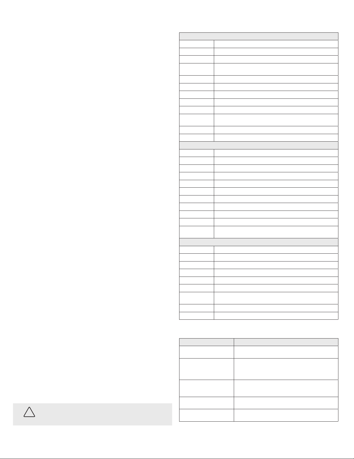
Specications
Camera
Image Sensor: 1/3” Progressive Scan CMOS
Signal System: NTSC
Eective Pixels: 1305 (H) × 1049 (V)
Min. Illumination: 0.001 lux @ (F1.2, AGC on),
0 lux with IR
Shutter speed: 1/60 sec to 1/50,000 sec
Synchronization Internal synchronization
Video Frame Rate 720p @ 60 fps
HD Video Output: 1 analog HD-TVI (BNC)
Video Output: (CVBS) 1 Vp-p composite output (75 Ω/BNC)
Lens: 2.8 - 12 mm @ F1.4
Angle of view: 78° ~ 28°
Day & Night ICR
S/N Ratio > 62 dB
Menu
Automatic Exposure Global AE / DWDR
AGC Low / Middle / High / O
Slow Shutter Support
White balance Auto / Manual
D / N Mode Color / BW / SMART IR
3D DNR Low / Middle / High / O
Motion Detection Support, maximum 4 zones
Privacy Mask On / O, maximum 8 zones
UTC Function Support
Language English
Function, Digital Wide Dynamic Range, 3D Digital Noise Reduction, Sharpness, Brightness, Digital Zoom,
Mirror
General
Operating Conditions: -4 °F ~ 140 °F (-20 °C ~ 60 °C)
Humidity: 90% or less (non-condensing)
Power Supply: 12 Vdc
Power Consumption: 12 Vdc: Max. 4W
Weather Proof: IP66
IR Range: up to 131 ft (40 m) approx.
Communication In-line UTC controller
Protocol: Pelco-C (Coaxitron)
Dimension: Φ4.13" × 3.42" × 10.52” (Φ105 × 86.9 × 267.2 mm)
Weight: 2.98 lbs (1350 g)
TROUBLESHOOTING
Problem Possible Cause
Nothing appears on the screen - Check the power connection.
- Check the video signal cable connection to the monitor.
The video image is dim or not clear. - If the camera lens is dirty, clean it with a soft, clean cloth.
- Adjust the monitor controls, if necessary.
- If the camera is facing a very strong light, change the camera position.
- Adjust the lens focus.
The screen is dark. - Adjust the contrast control of the monitor.
- If you have an intermediate device, set the impedance (75 Ω /Hi-Z)
properly, and check the cable connections.
The camera is not working properly and
the surface of the camera is hot.
- Verify that the camera is correctly connected to an appropriate regulated
power source.
The image on the monitor ickers - Make sure that the camera isn’t facing direct sunlight or uorescent light.
If necessary,change the camera position.