5www.observint.com © 2019 Observint Technologies. All rights reserved.
Digital Noise Reduction 3D DNR
WDR Digital WDR
Angle Adjustment Pan: 0° to 360°, tilt: 0° to 180°, rotation 0° to 360°
Lens
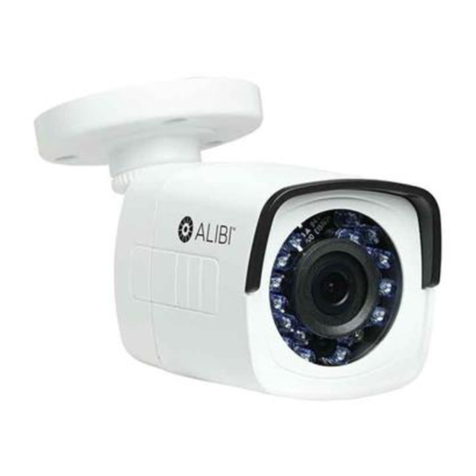
Focal Length, eld of view 2.8 mm, horizontal FOV 103°, vertical FOV 59°, diagonal FOV 118°
Aperture F2.0
Focus No
Lens Mount M12
IR
IR Range up to 100 ft Smart IR
Wavelength 850 nm
Compression Standard
Video Compression Main stream: H.265 / H.264
Sub-stream: H.265 / H.264 / MJPEG
H.264 Type Baseline Prole / Main Prole / High Prole
H.264+ Main stream supports
H.265 Type Main Prole
H.265+ Main stream supports
Video Bit Rate 32 Kbps ~ 8 Mbps
Smart Feature set
Region of Interest (ROI) 1 xed region for main stream and sub-stream
Image
Max. Resolution 1920 × 1080
Main Stream Max. Frame
Rate
50 Hz: 25 fps (1920 × 1080, 1280 × 960, 1280 × 720)
60 Hz: 30 fps (1920 × 1080, 1280 × 960, 1280 × 720)
Sub-stream Max. Frame
Rate
50 Hz: 25 fps (640 × 480, 640 × 360, 320 × 240)
60 Hz: 30 fps (640 × 480, 640 × 360, 320 × 240)
Image Enhancement BLC, 3D DNR
Image Settings Saturation, brightness, contrast, sharpness, AGC, white balance adjustable by client software or
web browser
Day/Night Switch Auto, Scheduled
Network
Network Storage NAS (NFS, SMB/CIFS)
On-board storage No
Alarm Trigger Motion detection, video tampering alarm, illegal login
Protocols TCP/IP, ICMP, HTTP, HTTPS, FTP, DHCP, DNS, DDNS, RTP, RTSP, RTCP, NTP, UPnP™, SMTP, IGMP,
802.1X, QoS, IPv6, UDP, Bonjour
General Function Anti-icker, heartbeat, mirror, password protection, privacy mask, watermark
API ONVIF (PROFILE S, PROFILE G), ISAPI
Simultaneous Live View Up to 6 channels
User/Host Up to 32 users 3 levels: Administrator, Operator and User
Client Alibi Central Management Software (ACMS) v3.1 or later, ACMS-XP
Web Browser Microsoft©Internet Explorer©8 and later
Interface
Communication Interface 1 RJ45 10M/100M self-adaptive Ethernet port
General
Operating Conditions -22 °F to 122 °F (-30 °C to 50 °C), humidity: 95% or less (non-condensing)
Power Supply 12 Vdc ± 25%, 5.5 mm coaxial power plug
PoE (802.3af, class 3)
Power Consumption and
Current
12 Vdc: 0.4 A, max. 5 W;
PoE: (802.3af, 36 V ~ 57 V), 0.2 A ~ 0.13 A, max. 7 W
Reset button No
Protection Level IP67 weatherproof
TVS 2000V lightning protection, surge protection and voltage transient protection
Material Plastic and metal
Dimensions Φ2.7” × 6.8” (Φ70 mm × 172.7 mm )
Weight Camera: approx. 0.62 lb. (280 g)
With package: Approx. 1.17 lb. (530 g)
Using the Waterproof Ethernet Fitting
Install the Waterproof Ethernet Fitting on the Ethernet cable end at the camera when moisture or
contamination exists in the area near the camera. The tting includes several parts that must be installed in
a specic order. To install the tting:
1. Place the rubber O-ring over the camera drop cable end cap.
Push the O-ring up to the connector cap.
2. If an RJ-45 connector is installed on the network cable, from
the router or switch, remove it.
3. Place the Lock Nut onto the network cable from the router
or switch as shown in the drawing to the right. The inside
threads must be toward the camera end.
4. Place the rubber basket onto the network cable above the lock
nut as shown.
5. Place the end cap onto the network cable above the rubber
gasket as shown. The ngered end must be toward the router
or switch.
6. Install an RJ-45 connector onto the network cable.
7. Plug the RJ-45 connector with the network cable into the
camera network drop cable.
8. Fit the end cap on the network cable onto the camera drop
cable end cap. Rotate the network cable end cap to lock it in
place.
9. Push the rubber gasket fully into the end of the network cable
end cap.
10. Screw the lock nut onto the network cable end cap until it is
fully seated.
Network drop
cable from
camera
Network cable from
router or switch
Fitting assembled
Waterproof Ethernet Fitting assembled and connected
Drop cable
end cap
Network drop
cable from
camera
Rubber
O-ring
seal
RJ-45
connector
End cap
Rubber
gasket
Network
cable
from
router or
switch
Lock nut
TVS 2000V Lightning and Surge Protection Feature Guidelines
This product includes TVS plate lightning protection technology to prevent damage caused by a pulse
signal that is below 3000 watts from sources such as lighting, surging, etc. Protection measures must be
taken to ensure electrical safety.
• The distance between signal transmission line and high-voltage equipment or high-voltage cable
is at least 50 m.
• Outdoor wiring should better be along the eaves as much as possible.
• In the open eld, wiring should be buried underground in sealed steel pipe with one-point
grounding. Overhead routing method is not acceptable.
• In regions with thunderstorms or where high induction voltage are present (such as high-voltage
transformer substation), high power lightning protection apparatus and lightning conductor are
necessary.
• The design for installation and wiring with lightning protection and grounding should be combined
with the lightning protection consideration of the building, and conform to the relevant national
and industry standards.
• The system should ensure equipotential grounding. Grounding equipment must satisfy both system
anti-jamming and electric safety. It must not allow short circuit and open circuit with the zero
conductor of strong grid. When the system is singularly ground, the resistance must less than 4 Ω
and the cross-sectional area of the grounding cable must be no less than 25 mm2. For grounding
instructions, refer to local electrical codes and this manual.
