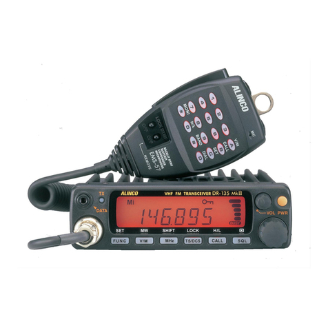
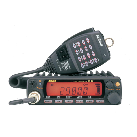
Alinco DR-140T User manual

DR-140T/E/TE1/TE2
Service Manual
C O N T E N T S
• SPECIFICATIONS
1) General................................................................................2
2) Transmitter................*
........................................................
2
3) Re eiver...............................................................................3
• CIRCUIT DESCRIPTION
1) Re eiver S ytem
.........................................................4-5
2) Transmitter System....................................................5-6
3) PLL Cir uit.........................................................................6
4) Terminal Fun tion of CPU...........................................7
• SEMICONDUCTOR DATA
1) AK2341
.
...........................................................................10
2) AN78L05M ................................................................... 11
3) LA4425A..........................................................................11
4) M 5218FP.........................................................................11
5) M56760FP......................................................................12
6) M67746............................................................................13
7) M68702H..........................................................................13
6) M68702L..........................................................................13
9) MC7808CT......................................................................14
10) RH5VL32AA-T1 ............................................................14
11) RH5VL45AA-T1 ............................................................14
12) TK10930VTL...................................................................15
13) j zPC2710T......................................................................16
14)24LC16B 16
15)
.
Transistor,Diode and LED Outline Drawings
.......
17
16) L C D ....................................................................................18
• EXPLODED VIEW
1) Bottom V iew
...................................................................19
2) LCD Assem bly...............................................................20
3) Top, and Front View.....................................................21
• PARTS LIST
Main Unit...................................................................... 21-22
Pa king.................................................................................23
CPU Unit...............................................................................23
SP Unit ................................................
.
.............................
23
VCO U nit.............................................................................23
Me hani al P arts..............................................................23
EJ-20U .................................................................................24
• ADJUSTMENT
1) Required Test Equipment
..........................................
25
2) PLL Adjustment.............................................................26
3) TX Adjustment
.........
.
...................................................26
4) RX Adjustment......
.
.......................................................27
5) Adjustment Points
........................................................28
• PC BOAD VIEW
1) Main Unit Side A ...........................................................29
2) Main Unit Side B...........................................................30
3) CPU Unit Side A ..........................................................31
4) CPU Unit Side B............................................................31
5) VCO Unit Side A ...........................................................32
6) VCO Unit Side B ...........................................................32
7) EJ-20U (CTCSS Unit: Option)..................................33
• BLOCK DIAG RA M ...................................................................34
• SCHEMATIC DIAGRAM
1) Main Unit T/E....................................................
.....
35-36
2) Main Unit TE1/TE2...............................................37-38
3) CPU U nit
........................................................................
39
4) VCO Unit
.............
.
..........................................................40
5) EJ-20U (CTCSS Unit: Option)
...............................
41
ALINCO, inc
SPECIFICATIONS
1) General
TX Frequen y Range:
RX Frequen y Range:
CTCSS En ode:
CTCSS De ode:
Mi rophone:
Frequen y Resolution
Antenna Impedan e:
Power Input:
Current Drain @13.8V DC:
Dimensions:
Weight:
Memory Channels:
Display:
Tone Bursts:
Time Out Timer:
Busy Channel Lo k Out:
Penalty Timer:
S an Fun tion:
2) Transmitter
Output Power (approx.):
Emission:
Modulation System:
Max. Frequen y Deviation:
Spurious Emission:
Operations:
TX/RX Offset Range:
T 144.000- 147.995MHz
E 144.000- 145.995MHz
TE1 136.000- 155.000MHz
TE2 150.000- 173.995MHz
T 118.000 - 135.995MHz (AM), 136.000 - 173.995MHz (FM)
E 144.000 - 145.995MHz (FM)
TE1 136.000 - 173.995MHz (FM)
TE2 136.000 - 173.995MHz (FM)
Standard 50 Tones
Optional 50 Tones
Ele tret Cond* with DTMF
5, 10, 12.5, 15, 20, 30, 50kHz steps, user adjustable
50Q unbalan ed
13.8 V DC ± 10%
RX - Squel hed: less than 800mA
TX - High: approx. 10.5A, Low: approx. 3.5A
141mm(W) x 41mm(H) x 154mm(D) (without proje tions)
approx. 0.86kg
50 Channels plus CALL hannel; ea h stores RX; TX offset,
CTCSS en ode, optional CTCSS de ode and alphanumeri display
information
Alphanumeri , English and Cyrilli alphabets, numbers 0-9, figures,
up to 7 hara ters; ba klit LCD
1000, 1450, 1750, 2100 Hz
30 to 450 se onds; sele table in 30 se ond in rements
Available - Requires Optional EJ20U CTCSS Tone De ode Unit
0-15 se onds
Busy or Timed; Up or Down, memory or VFO
High 50W / Low 5W (T/E), High 35W / Low 5W (TE1/TE2)
F3E FM
Variable Rea tan e Frequen y Modulation
± 5kHz
-60dB or under below arrier
Simplex or Semi-Duplex Modes
From 0 up to ± 99.995MHz (full tuning range of radio)
Offset may be saved as part of information stored in any memory
hannel

3) Re eiver
Re eiving System:
IF Frequen ies:
Sensitivity:
Sele tivity:
Audio Output:
Speaker Impedan e:
Dual Conversion Superheterodyne
First: 30.85MHz; Se ond: 455kHz
12dB SINAD -15dB|i
More than ± 6kHz at -6dB; Less than ± 15kHz at -60dB
More than 2.5 Watts @10% distortion
8£2
Spe ifi ations are subje t to hange without noti e or obligation. Performan e spe ifi ations apply only to
transmit bands. Names of ertain produ ts mentioned in this atalog are used for identifi ation purposes only
and may be trademarks or registered trademarks of their respe tive ompany.

CIRCUIT DESCRIPTION
1) Re eiver System
1. Antenna Swit hing Cir uit
(Main unit)
The signal from the anlenna is input to RF amplifier ir uit passing through the 5
stages low-pass filter (L15 ~ L18, C76 ~ C80, C148), the anlenna swit hing ir uit
(D9, D11, L14, C63), T type high-pass filter (L11, LI 2, C57, C64, C58, C59) and
band swit h ir uit (D20 T, E version only). The antenna swit hing ir uit uses XI4
diode swit h ir uit.
2. RF Amplifier Cir uit
(Main unit) RF signal is amplified approximately 2GdB by RF amplifier, RF amplifier ir uit
uses dual gate FET to get good inter-modulation hara teristi s. The RF amplifier
onsists of vollage tuned band-pass filter (L1, L2, L4, L5, D2, D3, D5, D6) and RF
AMP (Q6). The signal is amplified after eliminating unwanted signals so that
image interferen e hara teristi s are improved.
3. 1st Mixer Cir uit
(Main unit) The amplified signal is onverted into the first IF signal of 30.85MHz by mixer
ir uit (Q5). Mixer ir uit uses dual gate FET to improve multifrequen y hara ter
isti s su h as inter-modulation. The output signal from mixer ir uit is led fo 1st IF
ir uit.
4. Air Band Cir uit
(Main unit IT, E version) The output signal from band swit h ir uit is led to low-pass filter ir uit (L7, L8,
C55, C56) and input to RF amplifier ir uit (Q11). There the signal is amplified
approximately 20dB and input to the mixer ir uit.
5.1st IF Cir uit
(Main unit) The output 1 st IF signal from mixer ir uit is led to rystal filter XF1.
Unwanted frequen y band of IF signal is eliminated by a rystal filler. The result
ing signal is led to the 2nd IF amplifier, and the signal is output to 2nd IF ir uit.
6. 2nd IF Cir uit and Dete tor Cir uit
(Main unit) The 1st IF signal is led to 2nd mixer ir uit of IC1, then it is onverted into the 2nd
IF signal (455kHz) by 2nd lo al signal. IC1 has the 2nd mixer, 2nd lo al os illator
ir uit, quadrature dete tor ir uit and AM dete tor ir uit. The 2nd lo al os illator
os illates 2nd lo al signal (30.395MHz). The 2nd IF output signal from mixer (pin
3 of IC1) ir uit is led to erami filler {FL1). Unwanted frequen y band of 2nd IF
signal is eliminated by a erami filter. The resulting FM signal is led to the limiter
amplifier (pin 7 of IC1) ir uit and quadrature dete lor ir uit (pin 11 of IC 1 and
erami dis riminator Xt), and the 2nd IF signal is onverted to AF signal. The FM
AF signal is output from pin 12 of 1C1 to AF ir uit. The AM signal is input to AM
dete tor ir uit (pin 5 of IC1), and the AM AF signal is output from pin 13 of IC1.

7. AF and Mute Cir uit
(Main unit)
8. Squel h Cir uit
(CPU unit)
The AF signal from IC1 is filtered by the low-pass filter amplifier (Q2) and led to the
high-pass filter amplifier (Q1), and output to the AF gain volume. Q3 and Q4 are
swit hed ON/OFF by AFC signal from CPU, then AF signal is muted when the
squel h is ON.
IC1 has the noise amplifier, re tifier ir uit and omparator ir uit. The noise signal
from pin 12 of IC1 is input to the noise amplifier (pin19 of IC1) and passed through
buffer amplifier (Q28), re tified by D8, then it is input to omparator ir uit (pin 21
of IC1). When the noise signal is de reased by the re eiving signal, the ompara
tor output SD be omes low.
2) Transmitter System
1. Mi rophone Amplifier Cir uit
(CPU unit)
2. Limiter Amplifier Cir uit
(Main unit)
3. Modulation Cir uit
(VCO unit)
4. Drive Amplifier Cir uit
(Main unit)
The voi e from external mi rophone is amplified by the mi rophone amplifier
(Q303), and passed through the mi rophone mute ir uit (Q304), the signal is
input to the mi rophone gain potentiometer (VR3) in the main unit.
The signal from mi rophone gain potentiometer (VR3) is amplified by limiter
amplifier and low-pass (IC4). The resulting signal is passed through the modula
tion adjustment potentiometer (VR4), then input to VCO unit. IC4A is limiter
amplifier with pre-emphasis hara teristi s. IC4B is low-pass filter.
The adjusted AF signal in VR4 is led to the VCO unit. The frequen y modulation is
exe uted when the audio signal is supplied to the D207.
The signal from VCO unit is input to the drive amplifier (IC3). IC3 has high gain of
approximately 30dB and high level of approximately 10dBm wide band amplifier.
5. RF Younger Amplifier Cir uit
(Main unit) The signal from IC3 is passed through diode swit h D12, and input to younger
amplifier Q13. Q13 has approximately 15dB gain and output level is 400mW. The
output signal of younger amplifier is led to the PA amplifier (IC2).

6. RF Power Amplifier Cir uit
(Main unit)
7. Antenna Swit h Cir uit
(RF unit)
8. A PC Cir uit
(RF unit)
3) PLL Cir uit
1. Summary
2. Referen e Os illator Cir uit
(Main unit)
3. Loop Filter Cir uit
(VCO unit)
4. VCO Cir uit
(VCO unit)
IC2 is the power module, whi h obtains stable output power (50W T/E, 35W TE1/
TE2) within the band. The signal of younger amplifier is amplified by the PA
amplifier (IC2), and then led to the antenna swit h ir uit.
When transmitting, D11 and D9 are ON in the antenna swit h ir uit, L14 be omes
parallel omponents. This auses the output signal of IC2 not to go to the RX
ir uit. The signal is led to the antenna onne tor passing through the low-pass
filter (L15 ~ L18, C76 ~ C80, C148).
When the TX signal is passed through the low-pass filter, mat hing voltage and
mismat hing voltage are dete ted by the D14 and D15. When the antenna
impedan e is 50£2, the dete ted voltage of D14 and D15 are minimum. But when
the antenna impedan e is not 50ft, the dete ted voltage be omes higher. The
dete ted voltage is passed through the power setting potentiometer (VR1), and the
signal is amplified by Q17, Q16 and Q14. The transmitting power is ontrolled by
the voltage of V1 (IC2) and olle tor voltage of Q13. When the temperature of the
unit goes high, the powerdown ir uit (R104, TH2) prevents the devi e from being
damaged.
The PLL ir uit uses PLL IC (IC201) equipped with built-in dual modulus pres aler.
The PLL IC serial data is sent from CPU.
The VCO output frequen y divided by N is ompared with referen e frequen y in
the phase omparator.
The referen e frequen y is obtained by X3 (12.8MHz), and its output is led to the
VCO unit.
The phase error of phase omparator is integrated to DC voltage by loop filter
ir uit, and supplied to D201, D202 of vari ap diode jn VCO unit. The time
onstant of the a tive loop filter ( onsisting of Q202 and Q210) is determined by
C211, C212, R228, R210. The output is passed through the lag filter (R213,
C208), and input to VCO unit.
The ir uit is the Hartley os illator ir uit (Q201), and the signal is output passing
through the buffer amplifier (Q204). C247 is swit hed by D205 to vary the apa i
tan e, and the os illating frequen y range is shifted.

4) Terminal fun tion of CPU
No. Name Pin Name I/O Des ription H L H iZ Pull UP
1 AN7 SD ISD signal input Signal No signal
2 AN6 SMT I S meter signal input Analog
3 AN5 BP1 I Band plan Analog
4P64 UL IUnlo k input Unlo k Lo k
5 P63 TON1 0 Tone output 1 Pulse
6 P62 TON2 0 Tone output 2 Pulse
7P61 TON3 0 Tone output 3 Pulse r
8 P60 TON4 O Tone output 4 Pulse
9P57 AM 0 AM/FM sele tion AM FM
10 TOUT BEEP 0 Beep sound output, SCR ON-OFF Pulse
11 P55 - HL 0TX, Squel h level H/L Power
Squel h
Low
Low High
High
12 CNTR TBST 0 Tone burst output / mi rophone mute RX TX. Pulse
13 P53 T8 0 TX power supply ontrol TX OFF
14 P52 STB2
TICD 0ITone unit strobe
Tone unit dete tion input
Pulse
None
Normal
Equipped
15 P51 STB1 0 PLL strobe permitted Inhibited
16 INT2 RE2 I Rotary en oder down input OFF ON
17 P47 CLK 0 Clo k signal output Pulse
18 P46 DATA 0 Data signal output Pulse
19 TXD CTX 0 Data output for the loning mode Pulse
20 RXD CRX IData input for the loning mode Pulse
21 INT1 RE1 IRotary en oder up input OFF ON o
22 INTO BU IBa kup signal input Normal Ba kup o
23 P41 SQL 0 AF mute Mute Normal
24 P40 TSQD I Tone signal dete tion input No Tone Tone
25 RST RST IReset signal input at work
26 P71 SCL 0 Clo k input for E2PROM Pulse
27 P70 SDA 10 Data input for E2PROM Pulse
28 XIN XIN IInternal lo k input
29 XOUT XOUT 0 Internal lo k output
30 VSS GND I GND OV
31 P27 PTT IPTT key OFF ON o
32 P26 UP IUP key OFF ON o
33 P25 DOWN IDown key OFF ON o
34 P24 KEY 1 I Key 1 H/L OFF ON o
35 P23 KEY 2 IKey 2 SET OFF ON o

No. Name Pin Name I/O Des ription H L H iZ Pull UP
36 P22 KEY 3 IKey 3 CALL OFF ON o
37 P21 KEY 4 IKey 4 V/M OFF ON o
38 P20 KEY 5 I Key 5 FUN OFF ON o
39 S31 S31 0Segment 31 output Pulse
40 S30 S30 0 Segment 30 output Pulse
41 S29 S29 0 Segment 29 output Pulse
42 S28 S28 0Segment 28 output Pulse
43 S27 S27 0 Segment 27 output Pulse
44 S26 S26 0Segment 26 output Pulse
45 S25 S25 0Segment 25 output Pulse
46 S24 S24 0 Segment 24 output Pulse
47 S23 S23 0 Segment 23 output Pulse
48 S22 S22 0 Segment 22 output Pulse
49 S21 S21 0 Segment 21 output Pulse
50 S20 S20 oSegment 20 output Pulse
51 S19 S19 oSegment 19 output Pulse
52 S18 S18 oSegment 18 output Pulse
53 S17 S17 oSegment 17 output Pulse
54 S16 S16 0Segment 16 output Pulse
55 S15 S15 oSegment 15 output Pulse
56 S14 S14 0Segment 14 output Pulse
57 S13 S13 0Segment 13 output Pulse
58 S12 S12 0Segment 12 output Pulse
59 S11 S11 0Segment 11 output Pulse
60 S10 S10 0Segment 10 output Pulse
61 S9 S9 0Segment 9 output Pulse
62 S8 S8 0Segment 8 output Pulse
63 S7 S7 oSegment 7 output Pulse
64 S6 S6 oSegment 6 output Pulse
65 S5 S5 0Segment 5 output Pulse
66 S4 S4 oSegment 4 output Pulse
67 S3 S3 oSegment 3 output Pulse
68 S2 S2 oSegment 2 output Pulse
69 S1 S1 0Segment 1 output Pulse
70 SO SO oSegment 0 output Pulse

No. Name Pin Name I/O Des ription H L HiZ Pull UP
71 v VDD IPower supply
72 VREF VREF IReferen e voltage input
73 AVSS GND IGND
74 COM3 COM3 O LCD ommon 3 output Pulse
75 COM2 COM2 0LCD ommon 2 output Pulse
76 COM1 COM1 0LCD ommon 1 output Pulse
77 COMO COMO 0LCD ommon 0 output Pulse
78 VL3 VL3 ILCD power supply input
79 VL2 VL2 ILCD power supply input
80 VL1 VL1 ILCD power supply input
9

SEMICONDUCTOR DATA
1) AK2341 (XA0239)
CTCSS En oder/De oder
Pin
No.
Pin
Name I/O Fun tion
1RXIN IRX Signal Input
2RXINO 0AMP2 Output
3 TXINO oAMP1 Output
4TXIN I TX Audio Input
5RXOUT 0RX Audio Output
6TXOUT 0TX Audio Output
7VDD -Power Supply (1.8 ~ 5.5V)
8XIN ICrystal Terminal (3.6864MHz)
9XOUT oCrystal Terminal (3.6864MHz)
10 STB IStrobe for Serial Data
11 SDATA ISerial Data
12 SCLK ISerial Clo k
13 DCS IDCS Input
14 DETOUT 0Tone Dete tion Output (Dete t: Low)
15 VSS -Ground
16 DREF I Tone Dete tion Level Adjust Input
17 TLINP IRX Tone Signal Referen e Input
18 TLINN I RX Tone Signal Input
19 TLINO oAMP3 Output
20 RXTONE oRX Tone Signal Output
21 TXTONE oTX Tone Signal Output
22 AGNDIN IAnalog Ground Input
23 AGND 0Analog Ground Output
24 BIAS IBias Input
RXIN d = 124 Z U BIAS
RXINO n z 223 = ] AGND
TXINO n z 322 Z Z 2 AGNDIN
TXIN n z 421 = □ TXTONE
RXOUT n z 520 zzn RXTONE
TXOUT n z 6>
7s
PO 19 Z D TLINO
VDD n z 7CO 18 Z□TLINN
XIN n z 817 Z Z 3 TLINP
XOUT n z 916 =□ DREF
STB n z 10 15 =□ VSS
SDATA [Z Z 11 14 = l DETOUT
SCLK n z 12 13 =Z1 DCS
Blo k Diagram
10

2) AN78L05M (XA0238)
5V Voltage Regulator
u u u
Output Common Input
AN78L05M
3) LA4425A (XA0410)
5W Audio Power Amplifiers
1 2 3 4 5
4) M5218FP (XA0068)
Dual Low Noise
Operational Amplifiers Output 1 1
Inverting Input 1 2
Non Inverting Input 1 3
Power Supply Minus 4
8 Power Supply Plus
7 Output 2
6 Inverting Input 2
5 Non Inverting Input 2

5) M56760FP (XA0235)
540MHz Frequen y Synthesizer
XIN
XOUT
FIN
REF
SI
CPS
RST
Serial data input
terminal S l t = 116 =]v
Clo k input terminal ere n z 215 XIN
Reset input terminal RST C Z 3
2
14 ZZÏ XOUT
Referen e Bias
input terminal REF tZZ 4CJ1
o
o>
o
T I
"U
13 H D LOCK
Lo al Os illator input
terminal fmax =540MHz FIN n z 512 ZZÏPD
Output portl terminal swi n z 611 =□ LFI
Output port2-terminal SW2 I—710 ZZ] LFO
Ground terminal GNDI
----
89= D P /N
Power supply
terminal
3 -5 .5 V 14mA
Referen e os illator
input terminal
Referen e os illator
output terminal
Phase dete tor output
terminal
when lo ked Low
Phase dete tor output
terminal
Low pass filter input
terminal
Low pass filter
output terminal
Phase swit h input terminal
of phase omparator
Fun tion Table
P/N input Phase PD output
High or Low Lo ked Hi-Z
High Lead High
High Lag Low
Low Lead Low
Low Lag High
LFI LFO

6) M67746 (XA0412)
144- 148MHz 60W
RF Power Module
*o
3DM67746
12 3 4
C
>
CO ouq
□vi
I ? a>
O)
Z E
3 O «
to
R-e
CLO 4-* Q. ^
C CO CO
— *>
9-in
Q ^
s !
il £
~o
3
$
o
CO
ro
D C
f i
o .£
Ratings Symbol Ratings Unit
Supply voltage V 17 V
Total urrent I 20 A
Input power Pin (max) 600 mW
Output power Po(max) 70 W
Operation ase temperature T (op) -30 to +110 °C
Storage temperature Tstg -40 to +110 °0
Zg=ZI=50Q
7) M68702H (XA0444)
150- 175MHz 60W
RF Power Module (TE2)
Ratings Symbol Ratings Unit
Supply voltage V 17 V
Total urrent I 20 A
Input power Pin (max) 600 mW
Output power Po(max) 75 W
Operation ase temperature T (op) -30 to +110 °C
Storage temperature Tstg -40 to +110 °C
Zg=ZI=50ii
8) M68702L (XA0445)
135- 160MHz 60W
RF Power Module (TE1)
Ratings Symbol Ratings Unit
Supply voltage V 17 V
Total urrent I 20 A
Input power Pin (max) 600 mW
Output power Po(max) 75 W
Operation ase temperature T (op) -30 to +110 °C
Storage temperature Tstg -40 to +110 °C
Zg=ZI=50i2

9) MC7808CT (XA0082)
8V Voltage Regulator
Test Cir uit
10) RH5VL32AA-T1 (XA0198)
C-MOS Voltage Dete tor
Equivalent Cir uit
.VDD
OUT
vss
U Ü u
OUT VDD VSS
RH5VL32AA
11) RH5VL45AA-T1 (XA0208)
C-MOS Voltage Dete tor
Equivalent Cir uit
lv d d
OUT
VSS
m i ' i t
OUT VDD VSS
RH5VL45AA
14

12) TK10930VTL (XA0223)
Narrow Band FM IF IC
IF in O
1 0 .7 M H z
51
/ 1
z 1-
3
C L .
Z n
ü.
4 7K A F O U T P U T (A M )
r - 0
F M A F O U T A F O U T P U T (F M )
i r °
Parameter Symbol Ratings Unit
Supply voltage V max 10.0 V
Power dissipation Pd 400 mW
Storage temperature Tstg -55-+150 °
Operating temperature Top -30-+75 °
Operatingvoitage Vop 2.5-8.5 V
Operating frequen y (op -6 0 MHz Ta=25°C V =3V
Ratings Unit Condition
Parameter oym ooi Min Typi al Max
Supply Current 1 I 1 6.8 8.9 mA No signal. AM ON
Supply Current 2 1 2 3.9 5.3 mA No signal, AM OFF
Mixer Conversion Gain Mg 20 dB
Mixer tnput Impedan e Mz 3.6 KQ DC Test
FM
Limiting Sensitivity Limit 2.0 8.0 tiV -3.0dB
Output Voltage Vo1 85 150 230 mVrms 10mVin +/-3kHz DEV
Distortion THD1 1.0 2.0 % 10mVin +/-3kHz DEV
Output Impedan e Zo 800 n lOm Vin
Filter Gain Gf 30 38 dB Fin=30kHz, Vo=100mV
S an Control Hi Voltage SH 2.3 V Squel h input=2.5V
S an Control Low Voltage SL 0.3 VSquel h input=0V
Squel h Hysteresis Hys 30 mV
S meter Output Voltage SO 0.05 0.5 V Vin=0mV, RS=68kS2
S meter Output Voltage S1 0.05 0.5 0.9 V Vin=0.01mV, RS=68kfi
S meter O utput Voltage S2 0.7 1.2 1.7 VVin=0.1mV, R S=68kii
S meter O utput Voltage S3 1.2 1.8 2.5 V Vin=1mV, RS =68kii
S meter Output Völtage S4 1.6 2.3 2.9 V Vin=1 OmV, RS=68ki^
S meter Output Voltage S5 1.8 2.4 2.9 VVin=100mV, RS=68ki2
AM
Sensitivity US 20 15 JiV required input level to gel
20mV rms output
Output Voltage Vo2 60 120 160 mVrms 1kHz, 30%, Vin=1mV
Distortion-1 THD2 1.0 2.0 % 1kHz, 30%, Vin=1mV
Distortion-2 THD3 2.0 4.0 %1kHz, 30%, Vin=1 mV
S/N S/N 40 48 dB 1kHz, 30%. Vin=1mV
AM OFF Vo -0.3 0.3 %

13) nPC2710T (XA0449)
RF Amplifier
Parameter Symbol Condition Ratings Unit
Supply voltage V 5.0 V
Cir uit urrent I V =5V, no signal 22 mA
Power gain GP V =5V, f=500MHz 33 dB
Saturated output power Po(sat) V =5V, f=500MHz, Pin=-8dBm +13.5 dBm
Noise figure NF V =5V, f=500MHz 3.5 dB
Upper frequen y (-3dB) fu V =5V, Referen e freq. =100MHz 1000 MHz
Isolation ISL V =5V, f=500MHz 39 dB
Input return loss RLin V =5V, f=500MHz 6 dB
Output return loss RLout V =5V, f=500MHz 12 dB
Gain flatness aGpV =5V f=0.1 ~ 0.6GHz ±0.8 dB
Test Cir uit
______
V Top View
GND
GND QT
Input O
Output
1F| GND
V
14) 24LC16B (XA0351)
16K bits CMOS Serial EEPROM
Blo k Diagram
__________________
WP
AO n z 1IO 8H3 V
A1 \z z 2-1^
1“ 7z n WP
A2 n z 3O
o> 6Z Z ] SCL
Vss 4CD 5Z Z i SDA
Pin Name Des ription
Vss GND terminal
SDA Serial address/data I/O
SCL Serial lo k
WP Write prote t
V +2.5V-5.5V power supply
A0, A1, A2 No onne tion

15) Transistor, Diode and LED Outline Drawings
T o p V i e w

16) LCD
LCD Pattern
EEia_ENC 4 DjEC 6^+
M M l ly / l ly / l w ly / l ly / l M
i m i i s i m r n r n m m n r ,
lo w mm i
LCD onne tion table
No. COM.O COM.1 COM.2 COM.3 No. COM.O COM.1 COM.2 COM.3
1COM.O 21 8a 8b 8g 8
2 COM.1 22 M9f 9e 9d
3 COM.2 23 9a 9b 9g 9
4COM.3 24 7i 7h 7n 7m
5COM.O 25 —7f 7e 7d
61j 1k ig 11 26 6i 6h 6n 6m
71a 1b 1 LOW 27 +6f 6e 6d
82j 2k 2g 21 28 5i 5h 5n 5m
92a 2b 2 BUSY 29 DEC 5f 5e 5d
10 3j 3k 3g 31 30 4i 4h 4n 4m
11 3a 3b 3 • (D 31 1 © 4f 4e 4d
12 4] 4k 4g 41 32 3i 3h 3n 3m
13 4a 4b 4 • (2) 33 1 © 3f 3e 3d
14 5j 5k 5g 51 34 2i 2h 2n 2m
15 5a 5b 5 ■ (3) 35 ENC 2f 2e 2d
16 6j 6k 6g 61 36 1i 1h in 1m
17 6a 6b 6 ■ @ 37 FUNC 1f 1e 1d
18 7j 7k 7g 71
19 7a 7b 7 FULL
20 •m 8f 8e 8d
18

EXPLODED VIEW
19

3) Top and Front Views
S rew Torque: 5kg m AE0014
KZ0047Z
AE0014 AE0014
AE0014
ES0017
EM0152 UA0037Z
FG0040 [T. E: XA0412 (M67746)
TE1: XA0445 (M68702L)
1.TE2: XA0444 (M68702H)
UX1047
YZ0062
FP0004
AD0010 AD0010
AV0001 FF0028
AV0001
KZ0039A
AV0001
NB0063Z
AE0014
KZ0045Z
KZ0040A
AE0014
A t O U 1 4
KS0041CZ
Other manuals for DR-140T
1
This manual suits for next models
3
Table of contents
Other Alinco Receiver manuals

Alinco
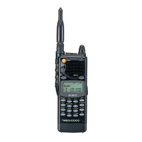
Alinco DJ-X2000T User manual

Alinco
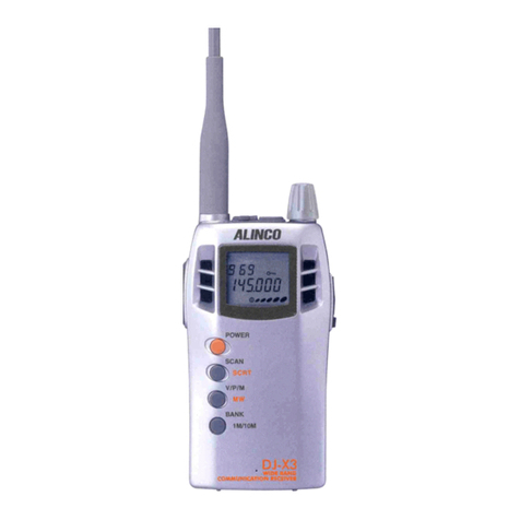
Alinco DJ-X3 User manual

Alinco
Alinco DJ-X3 User manual

Alinco
Alinco DJ-X2 E User manual

Alinco
Alinco DJ-X2 E User manual

Alinco
Alinco DJ-X10 User manual

Alinco
Alinco DJ-X10 User manual

Alinco
Alinco DJ-X3 T User manual

Alinco
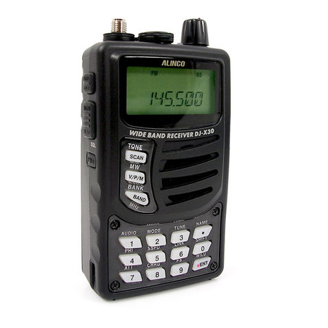
Alinco DJ-X30T User manual

Alinco
Alinco DR-M03R User manual

Alinco
Alinco DX-R8T User manual

Alinco
Alinco DR-150T User manual

Alinco
Alinco DR-135 User manual

Alinco
Alinco DJ-191 User manual

Alinco
Alinco DJ-180 User manual

Alinco
Alinco DJ-X3 User manual

Alinco
Alinco DJ-X7E Installation guide

Alinco
Alinco DJ-191 User manual

Alinco
Alinco DJ-X2000 User manual

Alinco
Alinco DJ-X1 User manual