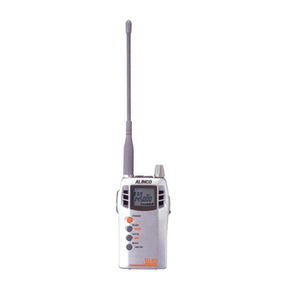
Alinco DJ-191 User manual

Service Manual
CONTENTS
•SPECIFICATIONS.......................................................2
•CIRCUIT DESCRIPTION............................................3
•SEMICONDUCTOR DATA........................................9
•E PLODED VIEW.......................................................15
•PARTS LIST
.............................................................. 18
•ADJUSTMENT...........................................................21
•P C BOARD VIEW.......................................................26
•CIRCUIT DIAGRAM...................................................41
• BLOCK DIAGRAM...................................................45
ALINCO, INC

SPECIFICATIONS
Frequency Coverage
DJ-191T (u .S. Amateur version)
DJ-191E (European Amateur version)
D J -191T A1 (Commercial version VHFL)
DJ-191TA2 (Commercial version VHFH)
Channel Step:
Memory Channels:
Antenna Impedance:
Frequency Stability:
Microphone Input Impedance:
Signal Type:
Offset Range:
Deviation:
T Output (supply voltage):
R Sensitivity:
R Selectivity:
I.F.:
Power Supply Requirements:
Current Consumption
at 13.8V DC:
Operating Temperature:
Dimensions:
(with EBP-37N without projections)
Weight:
DTMF:
Subaudible Tones (CTCSS):
T R
144.000 ~ 147.995MHz 135.000 ~ 173.995MHz
144.000 ~ 145.995MHz 144.000 ~ 145.995MHz
135.000 ~ 155.000MHz 135.000 ~ 173.995MHz
150.000 ~ 173.995MHz 135.000 ~ 173.995MHz
5, 10, 12.5, 15, 20, 25, 30kHz steps
40 Channels +1 Call Channel Memory
50£2 unbalanced
±5 ppm
2ki2 nominal.
F3E (FM)
0~ 99.995MHz
±5kHz max.
1.5W (4.8V) / 3.5W (7.2V) / 5W (9.6 ~ 13.8V)
12dB SINAD better than - 16dB/i
-6dB / ± 12kHz
(1st) 21.25MHz / (2nd) 450kHz
4.8 ~ 13.8V DC (4.8V DC standard)
Transmitting: Approx. 1.2 Amp. in High Power
Setting
Receiving: Squelched Approx. 24mA (BS on)
-1 0 - +60°C, 14 — 140°F
57(W) x l 51 (H)x 28(D) mm
21A(W) x 6(H) x 11/i6(D) inches
Approx. 300g
16 Button Keypad, encoder/decoder installed
Encoder installed (50 tones)

CIRCUIT DESCRIPTION
1) Receiver System
1. Front End
2. IF Circuit
3. Demodulator Circuit
4. Audio Circuit
The receiver system is a double superheterodyne system with a 21.7 MHz
first IF and a 450 kHz second IF.
The received signal at any frequency in the 130.00- to 173.995-MHz range
is passed through the low-pass filter (L102, L103, L104, C113, C107, C116,
and C114) and tuning circuit (L112 and D107), and amplified by the RF
amplifier (Q107). The signal from Q107 is then passed through the tuning
circuit (L109, L110, L111, and varicaps D104, D105 and D106) and
converted into 21.7 MHz by the mixer (Q106). The tuning circuit, which
consists of L112, L109, varicaps D107 and D104, L110, L111, varicaps
D105 and D106, is controlled by the tracking voltage from the CPU so that
it is optimized for the reception frequency. The local signal from the VCO is
passed through the buffer (Q108), and supplied to the source of the mixer
(Q106). The radio uses the lower side of the superheterodyne system.
The mixer mixes the received signal with the local signal to obtain the sum
of and difference between them. The crystal filter ( F101, F102) selects
21.7 MHz frequency from the results and eliminates the signals of the
unwanted frequencies. The first IF amplifier (Q105) then amplifies the
signal of the selected frequency.
After the signal is amplified by the first IF amplifier (Q105), it is input to pin
16 of the demodulator IC (IC104). The second local signal of 21.25 MHz
(shared with PLL !C reference oscillation), which is oscillated by the internal
oscillation circuit in IC102 and crystal ( 101), is input through pin 1 of
IC104. Then, these two signals are mixed by the internal mixer in IC104
and the result is converted into the second IF signal with a frequency of 450
kHz. The second IF signal is output from pin 3 of IC104 to the ceramic filter
(FL101), where the unwanted frequency band of that signal is eliminated,
and the resulting signal is sent back to the IC104 through pins 5 and 7.
The second IF signal input via pin 7 is demodulated by the internal limiter
amplifier and quadrature detection circuit in IC104, and output as an audio
signal through pin 9.
The audio signal from pin 9 of IC104 is compensated to the audio
frequency characteristics in the de-emphasis circuit (R162, R161, C172,
C173) and amplified by the AF amplifier (Q109). The signal is then input to
pin 2 of the electronic volume (IC103) for volume adjustment, and output
from pin 1. The adjusted signal is sent to the audio power amplifier (IC105)
through pin 2 to drive the speaker.

5. Squelch Circuit Part of the audio signal from pin 9 of IC104 is amplified by the noise filter
amplifier consisting of R176, R186, R177, C179, C183, C191, and C194,
and the internal noise amplifier in IC104. The desired noise of the signal is
output through pin 11 of IC104, to be further amplified by the noise amplifier
(Q115). The amplified noise signal is rectified by voltage doubler D109 and
input to pin 4 of CPU (IC5).
2) Transmitter System
1. Modulator Circuit The audio signal is converted to an electric signal in either the internal or
external microphone, and input to the microphone amplifier (IC6). IC6
consists of two operational amplifiers; one amplifier (pins 1, 2, and 3) is
composed of pre-emphasis and IDC circuits and the other (pins 5, 6, and 7)
is composed of a splatter filter. The maximum frequency deviation is
obtained by VR2 and input to the cathode of the varicap of the VCO, to
change the electric capacity in the oscillation circuit. This produces the
frequency modulation.
2. Power Amplifier The transmitted signal is oscillated by the VCO, amplified by the pre-drive
Circuit amplifier (Q102) and drive amplifier (Q101), and input to the power module
(IC101). The signal is then amplified by the power module (IC101) and led
to the antenna switch (D101) and low-pass filter (L102, L103, L104, C113,
C107, C116, and C114), where unwanted high harmonic waves are
reduced as needed, and the resulting signal is supplied to the antenna.
3. APC Circuit Part of the transmission power from the low-pass filter is detected by D1Q3,
converted to DC, and then amplified by a differential amplifier. The output
voltage controls the bias voltage from pin 2 of the power module (IC101) to
maintain the transmission power constant.
3) PLL Synthesizer Circuit
1. PLL The dividing ratio is obtained by sending data from the CPU (IC5) to pin 2
and sending clock pulses to pin 3 of the PLL IC (IC102). The oscillated
signal from the VCO is amplified by the buffer (Q117) and input to pin 6 of
IC102. Each programmable divider in IC102 divides the frequency of the
input signal by N according to the frequency data, to generate a
comparison frequency of 5 or 6.25 kHz.
2. Reference Frequency The reference frequency appropriate for the channel steps is obtained by
Circuit dividing the 21,25 MHz reference oscillation ( 101) by 4250 or 3400,
according to the data from the CPU (IC5). When the resulting frequency is
5 kHz, channel steps of 5,10,15, 20, 25, 30, and 50 kHz are used. When
it is 6.25 kHz, the 12.5 kHz channel step is used.
3. Phase Comparator The PLL (IC102) uses the reference frequency, 5 or 6.25 kHz. The phase
Circuit comparator in the IC102 compares the phase of the frequency from the
VCO with that of the comparison frequency, 5 or 6.25 kHz, which is
obtained by the internal divider in IC102.
4. PLL Loop Filter Circuit If a phase difference is found in the phase comparison between the
reference frequency and VCO output frequency, the charge pump output
(pin 8) of IC102 generates a pulse signal, which is converted to DC voltage
by the PLL loop filter and input to the varicap of the VCO unit for oscillation
frequency control.
5, VCO C ircuit A Colpitts oscillation circuit driven by Q301 directly oscillates the desired
frequency. The frequency control voltage determined in the CPU (IC5) and
PLL circuit is input to the varicaps (D301 and D304). This changes the
oscillation frequency, which is amplified by the VCO buffer (Q302) and
output from the VCO unit.
Note
The oscillation frequency is determined by turning Q301 ON and OFF.
Displayed frequencies Q301
T : 130.00 -139.995 MHz
R : 130.00- 161.695 MHz OFF
T : 140.00-173.995 MHz
R : 161.70- 173.995 MHz ON
4) CPU and Peripheral Circuits
1. LCD Display Circuit The CPU turns ON the LCD via segment and common terminals with 1/3
the duty and 1/3 the bias, at the frame frequency is 85Hz.
2. Display Lamp Circuit When the LAMP key is pressed, “H” is output from pin 45 of CPU (IC5) to
the bases of Q1 and Q12. Q1 and Q12 then turn ON and the LEDs (D1,
D3, D14, D15, D16, and D17) light.
3. Reset and Backup
Circuits
When the power from the DC jack or external battery increases from 0 V to
2.5 or more, “H” level reset signal is output from the reset IC (IC2) to pin 35
of the CPU (IC5), causing the CPU to reset. The reset signal, however,
waits at C6 and R1Q10, and does not enter the CPU until the CPU clock
( 1) has stablized. When the external power drops to 3.2 V or below, the
output signal from the backup IC (IC3), which has been input to pin 34 of
the CPU, changes from “H” to “L” level. The CPU will then be in the backup
state.
5

4. S(Signal)Meter Circuit The DC potential of pin 13 of IC104 is input to pin 3 of the CPU (IC5),
converted from an analog to a digital signal, and displayed as the S-meter
signal on the LCD.
5. DTMF Encoder The CPU (IC5) is equipped with an internal DTMF encoder. The DTMF
signal is output from pin 12, through R90 and R91 (for level adjustment),
and then through the microphone amplifier (IC6), and is sent to the varicap
of the VCO for modulation. At the same time, the monitoring tone passes
through the AF circuit and is output from the speaker.
6. DTMF Decoder Part of the audio signal demodulated by IC104 is input to pin 1 of DTMF IC
(IC8). The internal signal judging circuit in IC 8 then checks if the signal is
valid or invalid. The judged signal is converted into a 4-bit code and sent to
pin 29 of 1C5.
7. Tone Encoder The CPU (IC5) is equipped with an internal tone encoder. The tone signal
(67.0 to 254.1 Hz) is output from pin 11 of the CPU to the varicap of the
VCO for modulation.
5) CPU Terminal Functions: M38267M8L ( A0413)
C C C 3 C 3 C 5 0 C 3 C 3 C 5 C 5 C 5 C 5 C 5 0 0 0 0 0 0 0 0 0
e «, » » • ^LDLDLDLDLDlULDLDLDLDUJLDLDLDLDUJUJLUlULDllILD
UIUJliJUJUJlUlUlilcocococococococooooooir)oo*-*-T-’-*-T-
CflCflCflC/)c/)c/)c/)C/)Q =Q=Q=Q=Q=Q=Q»Qs Q -G -G -Q -G _G -Q .Q .Q _ Q _Q .& Q _ Q _
t m m t m i m 11111 m 1111111
SEGg
r r A
OCVJg
s e g 7
SEGs
SEG6
s e g <
SEG,
SEG2
SEG,
SEG»
Vcc
V„EF
AVss
COM,
COM2
COM,
COM»
V u
V u
C2
_ | m
m
• [99
A0413
^Ju
U -
m .
4 7 ]-
44| -
ID-
40]
3 D -
-p u
-P17
-P 2 „
-P2,
-P 2 2
-P 2 3
- P2<
-P 2 6
•P2s
-P 2 7
V«
' oUT
- |N
" XcoUT
“ ciN
-RESET
- P7o/INTO
-P7,
-P72
- P7S

No. Pin Name Signal I/O I Logic Description
1C1 C1 - - -
2VL1 VL1 1A/D LCD power supply
3P67/AN7 SMT 1A/D S-m eter input
4 P66/AN6 SQL 1A/D Noise level input for squelch
5P65/AN5 BAT 1A/D Low battery detection input
6P64/AN4 BP5 1A/D Band plan 5
7P63/CLK22/AN3 BP4 1-Band plan 4
8P62/CLK21/AN2 UL 1Active high PLL unlock signal input
9P61/SOUT2/AN1 BP1,2 1A/D Band plans 1 and 2
10 P60/SIN2/AN0 MONI 1 Active low Monitor key input
11 P57/ADT/DA2 CTOUT 0 D/A CTCSS tone output
12 P56/AD1 DTOUT 0 D/A DTMF output
13 P55/CNTR1 TSQD iActive iow CTCSS tone detection input/Trunking board detection
14 P54/CNTR0 BEP 0 Pulse Beep tone output/Band plan 3
15 P53/RTP1 STB2 I/O Active low/pulse CTCSS unit detection/Strobe signal to CTCSS unit/Strobe signal to trunking board/Audio line control
16 P52/RTP0 MUTE I/O Active high Microphone mute/Bank change input while trunking
17 P51/PWM1 CLK 0Pulse Serial clock output for PLL, CTCSS, and trunking board
18 P50/PWM0 DATA 0 Pulse Serial data output for PLL, CTCSS, and trunking board
19 P47/SRDY1 ACK I/O Pulse Clock output for DTMF shift out/Band plan 6
20 P46/SCLK1 STB1 0 Pulse Strobe for PLL IC
21 P45/T D1 UT 0 Pulse UART data transmission output
22 P44/R D1 UR 1 Pulse UART data reception input
23 P 43W TO UT TBST 0 Pulse Tone burst (1750Hz) output (European version)
24 P42/INT2 RE2 1 Active low Rotary encoder input
25 P41/INT1 RE1 1Active low
26 P40 PTT 1 Active high PTT input
27 P77 DSW 0 Active low DTMF IC ON/OFF
n o
¿O r /o OTPv
O I u 1 (A
l/w Active high DTMF signal detection input during reception/ueviation adjustment during transmission
29 P75 DSD 1Pulse Decoded DTMF serial data input during reception/Deviation adjustment during transmission
30 P74 T3C 0 Active low T power ON/OFF output
31 P73 P3C 0 Active low PLL power ON/OFF output
32 P72 AFP 0 Active low AFAMP power O N/OFF output
33 P71 R3C 0 Active low R power ON/OFF output
34 P70/INTO BU 1Active low Backup signal detection input
35 RESET RST 1 Active low Reset input
36 CIN CIN ---
37 COUNT COUT - - -
38 IN IN --Main clock input
39 OUT OUT - - Main clock output
40 VSS GND --CPU ground
41 P27 PSW 1Active low Power switch input
42 P26 SCL 0 Pulse Serial clock for EEPROM
A OD O C
i e—j POP r\ u;~u
1 IILjJ I C3 power ON/OFF output
44 P24 SDA 0 Pulse Serial data for EEPROM
45 P23 LMP 0 Active high Lamp ON/OFF
46 P22 T/KEY 1Active low Tone burst/LPTT input
47 P21 KOO I/O - Key matrix output/Band plan BP7 input
48 P20 K01 0 -
49 P17 K02 0 - Key matrix output
50 P16 K03 0-

No. Pin Name Signal I/O Logic Description
51 P15/SEG39 F/KEY IActive low Function key input
52 P14/SEG38 K10 I-
53 P 13/S EG 37 K11 I-
54 P 12/S EG 36 K12 I-Key matrix input
55 P11/SEG35 K13 I -
56 P10/SEG34 K14 I-
57 P07/SEG33 SFT 0-VCO frequency range change
58 P06/SEG32 SD 0Active low Signal detection output
59 P05/SEG31 AFC 0Active high AF tone control output
60 P04/SEG30 DA4 0-
61 P03/SEG29 DA3 0-
62 P02/SEG28 DA2 0-DA converter for electronic volume and output power
uw P01/SEG27 DA1 r\
V-
64 P00/SEG26 DAO 0-
65 P37/SEG25 S25 o -
66 P36/SEG24 S24 0-
67 P35/SEG23 S23 o-
68 P34/SEG22 S22 o-
69 P33/SEG21 S21 o-
70 P32/SEG20 S20 o-
71 P31/SEG19 S19 0-
72 P30/SEG18 S18 0-
73 SEG17 S17 0-
74 SEG16 S16 0-
75 SEG15 S15 0-
76 SEG14 S14 o-
77 SEG13 S13 o-LCD segment signal
7R SEG12 S12 o-
79 SEG11 S11 0-
80 SEG10 S10 0-
81 SEG9 S9 o-
82 SEG8 S8 0-
83 SEG7 S7 0-
84 SEG6 S6 0-
85 SEG5 S5 0-
86 SEG4 S4 0-
87 SEG3 S3 0-
88 SEG2 S2 0-
89 SEG1 S1 o-
90 SEGO SO 0-
91 VCC VDD --CPU power terminal
92 VREF VREF --AD converter power supply
93 AVSS AVSS - - AD converter ground
94 COM3 COM3 -- -
95 COM2 COM2 0-LCD COM2 output
96 COM1 COM1 0-LCD COM1 output
97 COMO COMO 0-LCD COMO output
98 VL3 VL3 I-LCD power supply
99 VL2 VL2 I-LCD power supply
100 C2 I-- -

SEMICONDUCTOR DATA
1) 24LC16BT-I/SN ( A0351)
EEPROM
Pin A ignment
AOC o
24LC01B □ Vss
Aie 24LC02B □ WP
A2C 24LC04B
n
At
r'rtO D
tiL ^ U O D □ SCL
VssC 24LC16B J S D A
Block Diagram
WP
2) LC73881M-TLM ( A0344)
DTMF Receiver
Pin Function
Pin nos. Signal I/O Description
1INPUT 1An input coupling capacitor is required. This input signal is internally biased by the V DD/2.
2 PD 1When this signal goes HIGH, the system enters the power-down mode.
3 OSCO 0These lines are connected to a crystal oscillator or a ceramic resonator of 194,304 MHz to
form the oscillation circuit.
4OSC! 1
5VSS -Power terminal (usually 0V).
6SD 0The decoded DTMF data is output as serial 4-bit data, starting with the LSB.
7ACK 1The ACK signal is used to shift out the data to pin 2 (PD). Four pulses are required to shift
out a four-bit DTMF code. The leading edge of the first pulse latches the data into the shift
register before shifting out.
8STD 0This signal goes HIGH when a DTMF code is sent. This signal changes LOW to HIGH
slower than the EST signal, however the burst frequency for this signal uses a dead band.
9EST 0This signal goes HIGH when a DTMF code is sent. This line is externally monitored to
determine an appropriate time, and then four pulses are input to the ACK terminal to allow
the SD terminal to output the DTMF data.
10 VDD - Power terminal (usually, 2.7 V to 5.5 V)

Block Diagram
PD Q ■ t Bias generating circuit Output signal
control circuit
INPUT O
-------
Anti-aliasing Alter
rtr= *=
Dial tone Alter -<>
Timing
generating circuit
High group
band pass filter Frequency detection
circuit
Low group
band pass fitter Frequency detection
circuit
to (j
- Ö -
osci osco
O ü
□EST
STD
Shift
register
0 ack
Ö S D
3) M5222FP-600C ( A0385) Electronic Volume
l=Vi/Ri
10

4) M64076GP ( A0352) PLL
Pin Assignment
XBo □1 20 □GND
SI c219 □Xln
CPS n3 18 □Xout
RST c17 □OP2
Vcc c516 □OP1
Fin 1 c615 □Fin2
Lockl c71 □Lock2
PD1 c813 □PD2
VT1 c9 12 □VT2
VF c10 11 □GND
Block Diagram
5) RH5VL25AA-T1 ( A0309)
C-MOS Voltage Detector 6) RH5VA32AA-T1 ( A0198)
C-MOS Voltage Detector
Block Diagram Block Diagram
11

7) MC3372VM-EL ( A0343)
Narrow Band FM IF IC
Block Diagram
GND
Vcc
8) NJM2070M T1 ( A0210)
Audio Power Amplifier
(TOP View)
12

9) NJM2100M T1 ( A0209)
Operational Amplifier
Pin A ignment Block Diagram
A OUTPUT C 0
18□ V*
A - INPUT C 27□ B OUTPUT
A +INPUT C 3 6□ B - INPUT
V- C4 5 □ B +INPUT
(TOP VIEW)
10) Transistor, Diode, and LED Ontline Drawings
l op View
DA204U T106 FMA7 T148 MA716TW MA741WA T MA742 T
D0130 U0027 D0118 D0251 D0250
f t
~ H — B T
fi fl fl
A 7 X L
n
lh
-----
ET
n
f l
- B
--------
B T n
aET
UN211HT
"‘ Üb04b'”‘
X L
6 P
xi— cr
UN2214T
ÚÓÓ38 UN9111 T
U0b62”' P1501 T
U0172
X L
8 D
" □
--------
□ "
X L
x r
6 A
IT
C1
£ L C2
XL
5 R
r m u
B1 E B2
13


t o
r
o
a
o
o
=J
CD
O
o ’
= j
y
>
s
O'
Gl
c
<D
C )
o
X X
> >
o o
-t*
ro co
— co
X
>
o

E PLODED VIEW
1) Front View 1
15

FG0173
0P12O3H
MBCKOZAA
FG0185

3) Rear View
AF0020
17

00
PARTS LIST
RôÎ- Doric IJi-i
Rel.
No. Paris No. D escription Parts Name Ver.
C PU Unit
Cl CU3035 Chip C. C1608JB1II102K A
C2 CU3035 Chip C. C1G08JB1H102K A
C3 CS0378 Chip antal HCHC0G107H R
C4 CU3017 Chip C. C1608CH1H330J A
C5 CU3017 Chip C. C1608CH1II330J A
C6 CS0201 Chip antal HCHA0G475H R
C7 CU3035 Chip C. C1608JBÍII102K A
C8 CU3035 Chip C. C1608JB1H102K A
C9 CSÜ378 Chip antal HCHC0G107H R
CIO CS0373 Chip antal HCHD1C476H R
C il CS0378 Chip antal MCHC0G1O7H R
Cl 2 CU3059 Chip C. C1608JP1E104Z A
C13 CS00G3 Chip antal HCSA1V104M R
CH CU3047 Chip C. C1608JB1H103K A
CIS CSÜ049 Chip antal MCSA1C105M R
CiG CS0057 Chip antal MCSAOJ225M R
CIS CS0049 Chip antal HCSA1C105M R
C19 CU3021 Chip C. C1G08CII1HG80J A
C20 CU3035 Chip C. C1608JB1H102K A
C21 CU3056 Chip C. C1608.IF1 E473Z A
C22 CU3035 Chip C. C1G08JB1H102K A
C23 CU3035 Chip C. C1S08JB1I1102K A
C24 CU3051 Chip C. C1Q08JIÎ1IÎ 223K A
C25 CU3051 Chip C. C1608JB1E223K A
C26 CU3027 Chip C. C1608CH11Ï221J A
C27 CU3035 Chip C. C1608JB1H102K A
C28 CU3026 Chip C. Cl 608C111 lil 81J A
C29 CU3027 Chip C. C1608CH111221J A
C30 CU3059 Chip C. C1B08JF1E104Z A
C31 CS00G3 Chip antal MCSA i V)04M R
C32 CIJ3059 Chip C. C1608JF1F.104Z A
C33 CU3035 Chip C. C1C08JB1H102K A
C35 CU3059 Chip C. C1B08JF1E1047. A
C37 CS0049 Chip antal MCSA 1C105M II
C39 CU3059 Chip C. C1G08JF1E1047. A
C40 CU3006 Chip C. C1608CH1II050C A
Cil CU3059 Chip C. C1808JF1E104Z A
C42 CU3035 Chip C. C160SJB11! 102K A
C43 CU3035 Chip C. C1G08JB1IÍ102K A
CM CU3035 Chip C. C1G08JB1H102K A
C45 CU3035 Chip C. C1G08JB1IU02K A
C46 CU3035 Chip C. C1608JB1I1102K A
C47 CU3035 Chip C. C1C08JB1H102K A
C48 CU3035 Chip C. C1608JB1II102K A
C49 CU3035 Chip C. C1G08JB1I1102K A
C52 CU3059 Chip C. C1608JP1E104Z A
CN1 UE0270 U.ire JACK-CPU Hire
CN2 UE025G CI' ’0508-0201
CN3 UP0282 DJG5 Flexible PCB
CN7 UE0267 AXN420C330P
D1 XL0045 LED PG1101F- R
1)3 XL0045 LED PG1101F- R
DS XL0047 LED PG1101W- R
D6 XL0048 LED BR1101W- R
D7 XD0291 Diode HA729- X
D9 XD0291 Diode HA729- X
Dll XD0250 Diode H/,742 X
D12 XD0291 Diode HA729- X
D13 XD0291 Diode HA729- X
D14 XL0036 LED SHL-310M 86
DIS XL0036 LED SHL-310H 8G
DIG XL0036 LED SHL-310H 86
1)17 XL0036 [.ED SML-310H 8G
Ref.
No. Parts No. Description Parts Name Ver.
ICI XA0351 EEP ROM 24LC1GB -1/SN
IC2 XA0309 IC RII5VL25AA- 1
IC3 XA0198 1C RH5VA32AA 1
1C4 XA0383 1C S - 81235SG-QI- 2
1C5 XA0413 1C M38267HL-0 P
ICO XA0209 1C NJM2100U 11
1 CS XA0344 1C LC73881H- LN
Ji HACLII2GG Vi re »30AII1 -025-111 . A.
AH.A3
LI QC0442 Chip 1,. MLF1608A1ROK AOÖ
L2 QC0442 Chip L. KLF1608A1ROK AOO
L3 QC0442 Chip L. HLF1608A1R0K A00
L4 QC0442 Chip L. HLF1G08A1R0K A00
L5 QC0442 Chip L. I1LF1608A1ROK AOO
Ql XU0145 ransistor D C143 U 10G
Q3 XU0040 ransistor UN 211 11 X
Q5 XU0040 ransistor UN211II X
Q7 XU0014 ransistor D C144EK 14G
Q9 XU00G4 ransistor- UN5210 X
010 XU00G4 ransistor UN5210 X
Qll X 0095 ransistor 2SC4081 Ï106R
Q12 XU0145 ransistor D C143 U 10G
Ql 3 XU0148 ransistor D C144EU 10G
Q14 XU0148 ransistor D C144EU 106
Ri RK3035 Chip R. ERJ3GSYJ581V
R2 RK30G2 Chip R. ERJ3GSYJ104V
R3 RK3035 Chip R. ERJ3G.SYJ5G1V
R4 RK3001 Chip R. F.RJ3GSY0R00V
R5 RK3001 Chip R. ERJ3GSY0R00V
R9 RK30G2 Chip R. ERJ3GSYJ104V
nie RA0009 Chip R. EXBV8V102JV
nil RA0010 Chip R. EXBV8V472JV
R12 RA0010 Chip R. EXBV8V472JV
R13 RK3038 Chip R. ER J3GSY.1102V
R14 RK3038 Chip R. ERJ3GSYJ102V
R15 RK3028 Chip R. ERJ3GSYJ151V
RIß RK3030 Chip II. ERJ3GSYJ221V
R18 RK3036 Chip R. ERJ3GSYJG81V
R19 RK3074 Chip R. ERJ3GSYJ105V
R20 RK3038 Chip R. ERJ3GSYJ102V
R21 RK3038 Chip R. ERJ3GSYJ102V
R22 RK3074 Chip R. ERJ3GSYJ105V
R23 RK3031 Chip R. ERJ3GSYJ27IV
R20 RK3Ü38 Chip R. ERJ3GSYJ102V
R27 RK3050 Chip R. ERJ3GSYJ103V
R28 RK3058 Chip R. ERJ3GSYJ473V
R3C RK3038 Chip R. ERJ3GSYJ102V
R31 RK3053 Chip R. ERJ3GSYJ183V
R32 RK3058 Chip R. ERJ3GSYJ473V
R33 RK3058 Chip R. ERJ3GSYJ473V
R34 RK3055 Chip R. F.RJ3GSYJ273V
R35 RK3058 Chip R. ERJ3GSYJ473V
R37 RK3038 Chip R. ERJ3GSYJ102V
R38 RK3041 Chip R. ERJ3GSY.1182V
839 RK3038 Chip R. ERJ3GSYJ102V
R40 RK30G8 Chip R. ERJ3GSYJ334V
R41 RK30G5 Chip R. ERJ3GSYJ184V
R42 RK3061 Chip R. ERJ3GSYJ823V
R43 RK3058 Chip R. ERJ3GSYJ473V
844 RK3054 Chip R. ERJ3GSYJ223V
R45 RK3001 Chip R. ER.J3GSY0R00V
R46 RK304G Chip R. ERJ3GSYJ472V
R47 RK3052 Chip R. ERJ3GSYJ153V
R48 RK3062 Chip R. ERJ3GSYJ104V

CPU Unit/CHARGE Unit/Mechanical Parts
Ref.
No. Parts No. Description Parts Mame Ver.
R49 RK3048 Ch P R. ERJ3GSYJ682V
ROO RK3050 Cli P R. ERJ3GSYJ] 03V
R51 ÜK3048 Ch P R. ERJ3GSY.JG82V
R52 RK3041 Ch p R- ERJ3GSYJ182V
R53 RK300G Ch P R. ERJ3GSYJ472V
R54 RK30C2 Cli P R. ERJ3GSYJ104V
R55 RK3050 Cli p R- EJÎJ3GSYJJ03V
R5G RK3066 Cli p R. ERJ3GSYJ224V
R57 RK3039 Cli P R. ERJ3GSY.il 22V
R58 RK3069 Cli P R. ERJ3GSYJ394V
1159 RK3051 Cli p R- ERJ3GSYJ123V
R60 RK3058 Cli p R. ERJ3GSYJ473V
R61 RK3054 Ch p R. ERJ3CSYJ223V
R62 RK3065 Ch p R- ERJ3CSYJ184V
R63 RK3056 Ch p R. ERJ3GSYJ333V
R64 RK3058 Ch p R. ERJ3GSYJ473V
R65 RK3Ö58 Cli P R. ERJ3GSYJ473V
RGB RK3055 Ch P R. ERJ3GSYJ273V
RG7 RK30G2 Ch P R- ERJ3GSYJ10-1V
R68 RK30G1 Ch p R. ERJ3GSYJ823V
RUS RK3050 Ch p R. ERJ3GSYJ103V
R70 RK3058 Ch p R- ERJ3GSYJ473V
R71 RK3034 Ch p R. ERJ3GSYJ471V
R72 RK3056 Ch p R. ERJ3GSVJ333V
R73 RK3051 Ch p R- ERJ3GSYJ123V
R75 RK3058 Ch p R- ERJ3GSYJ473V
R76 RK3038 Ch p R- ERJ3GSYJ102V
R79 RK3038 Ch p R. ERJ3GSYJ102V E
R80 RK3046 Ch P R. ERJ3GSYJ472V
R82 RK3058 Ch P R. ERJ3GSYJ473V
R83 RK3058 Ch p R- Eli J 3GSYJ 473 V
H84 RK3038 Ch P R. ERJ3GSYJ102V E
R86 RK3058 Ch P R. ERJ3GSYJ473V
R88 RK3038 Ch P R. ERJ3GSYJ102V
R89 RK3046 Ch P R. KRJ3GSYJ472V
R90 RK3056 Ch P R. ERJ3GSYJ333V
R91 RK3038 Ch p R. ERJ3GSYJ102V
R92 RK3001 Ch p R. ERJ3GSY0R00V
R93 RK3042 Ch P R. ERJ3GSYJ222V
R94 RK3031 Ch P R. ERJ3GSYJ271V
R96 RK3038 Ch p R- ERJ3GSYJ102V
R97 RK3038 Ch p R. ERJ3GSYJ102V
R98 RA0009 Ch P R. EXBV8V102JV
R99 RK1018 Ch p R. KRJ8GEYJ101V
R1001 RK3038 Ch p R- ERJ3GSYJ102V
R1002 RK3038 Ch p R. ERJ3GSYJ102V
R1004 RK3058 Ch P R. ERJ3GSYJ473V
R1005 RK3058 Ch p R- ERJ3GSYJ473V
R1006 RK3058 Ch p R. ERJ3GSYJ473V
R1007 RK3038 Ch P R. ERJ3GSYJ102V
R1008 RK3001 Ch p R- ERJ 3GSY0R00V E
R1009 RK3038 Cli p R. ERJ3GSYJ102V
R1010 RK3C50 Ch P R. ERJ3GSYJ103V
RIO 11 RK3C46 Ch P R. ERJ3GSYJ472V
R1012 RK3050 Ch p R- ERJ3GSYJ103V
R1013 RK3C50 Ch P R. ERJ3GSYJ103V
R1014 RK3C38 Ch p R. ERJ3GSY.I102V
R1015 RK3C38 Ch P R. ERJ3GSYJ102V
R1016 RK3C62 Ch p R- ERJ3GSYJ104V
R1017 RK3050 Ch p R- ERJ3GSYJ103V
R1018 RK3050 Ch p R- ERJ3GSYJ103V
R1019 RK3050 Ch P R. ERJ3GSYJ103V
R1020 RK3035 Ch p R. ERJ3GSYJ5G1V
R1021 RK3035 Ch p R. ERJ3GSYJ5G1V
Ref.
No. P arts No. D e s c rip tio n P arts Name Ver.
R1022 RK3035 Chip R. ERJ3GSYJ561V
R1023 RK3035 Chip R. ERJ3GSYJ561V
R1025 RK3001 Chip R. ERJ3GSY0R00V
R1027 RK3038 Chip R. ERJ3GSYJ102V
R1028 RK3038 Chip R. ERJ3GSYJ102V
R1029 RK3038 Chip R. ERJ3GSYJ102V
R1030 RK3058 Chip R. ERJ3GSYJ473V
R1031 RK3046 Chip R. ERJ3GSYJ472V
SW1 UU0018 Switch SOP- 112IIS
SW11 UU0018 Switch SOP-112ÍIS
XI XQ0074 Crystal SHD-49 4.19HHZ
UP0293B P.C.B DJ191 CPU PCB
C H A R G E Unit
C801 CHARGE A CU3031 C1608JB1H471K A
D801 CHARGE A XD0294 U2F«J44N( E12R)
D802 CHARGE A XD0294 U2FU.M4N( E12R)
D803 CHARGE A XD0290 HA111- X
D804 CHARGE A XD02G1 S3DG9
D805 CHARGE A XD0130 DA204U 106
JK801 CHARGE H UJ001S Il EC2781010510
0801 CHARGE A X 0088 2SA1213Y E12L
R801 CHARGE A RK0003 ERJ6GEYJ150V
R802 CHARGE A RK304G ERJ3GSYJ472V
Mechanical Parts
AF0020 Screw 0# 2+3Fe Ni
AX0001 Screw 0» 2+4 Fe Be
FP0093 erminal franic
FP0094 latch knob
SC0008 latch spring
SD0045 Batl tor’ninal
ISO 100 earth teriaini-;!
SOI 10 Charge earth
EY0014 EH-123A
DS0352A Spec.Card E A.
ÏAH.TA2
DS03G5 Spoc.Card T
EA0057Z Anlenna
EW0012 EDC-64 E. A.
TAH.TA3
PR0237 FCC P srll5 Seal T
EC0025 .Ni-Cd Battery Pack TAH.TS3
EG002G Ni-Cd Battery Pack T.E.TA
EV0011 Charger(EDCG3 120V) T
HK0392 Item Carton DJ191
Í1P0031 ProtecUon(Radio)
IHJ0077 Fixture
IHJ0085 Fixture D.IG5
IIU008G Fixture DJG5
PÍI0009 Registration Card
P 0004A hot Numbar Seal
IIP0028 Protection 185x280
PS0028 Screw Instruction Card
PK0058 Screw Schematic Diagram
AP0004 Screw P2+5FeZn
AX0001 0# P2+4Fe li/Cl
AX0002 OS p2+5FeNi]
DG0021 LCD Lainp DJ190
DP0105 LCD panel DJ190
EL0030 LCD XII618
ES0011 SU-3BW0824
FG0175 POWER Key DJG5
Other manuals for DJ-191
5
Table of contents
Other Alinco Receiver manuals

Alinco
Alinco DJ-X3 User manual

Alinco
Alinco DJ-X7E User manual

Alinco
Alinco DJ-X3 User manual

Alinco
Alinco DJ-X7E Installation guide

Alinco
Alinco DJ-191 User manual

Alinco
Alinco DJ-X3 User manual

Alinco
Alinco DJ-560T/E User manual

Alinco
Alinco DJ-X2000 User manual

Alinco
Alinco DR-150T User manual

Alinco
Alinco DR-M03R User manual

Alinco
Alinco DJ-X3 T User manual

Alinco
Alinco DJ-X2 E User manual

Alinco
Alinco DJ-180 User manual

Alinco
Alinco DJ-X30T User manual

Alinco
Alinco DR-140T User manual

Alinco
Alinco DJ-X2000T User manual

Alinco
Alinco DJ-X10 User manual

Alinco
Alinco DX-R8T User manual

Alinco
Alinco DR-135 User manual

Alinco
Alinco DJ-X1 User manual