Alinco DJ-X3 User manual

3
Contents
Features··········································································································5
NOTICE···········································································································6
Precautions·····································································································7
Request and Agreement·················································································7
Accessories····································································································8
Connecting the Antenna···········································································8
Attaching the Battery Case·······································································8
Loading the Batteries················································································9
The NiMH Battery Pack·············································································9
Prevent Short Circuiting the Battery Pack···············································10
Battery Recharger···················································································11
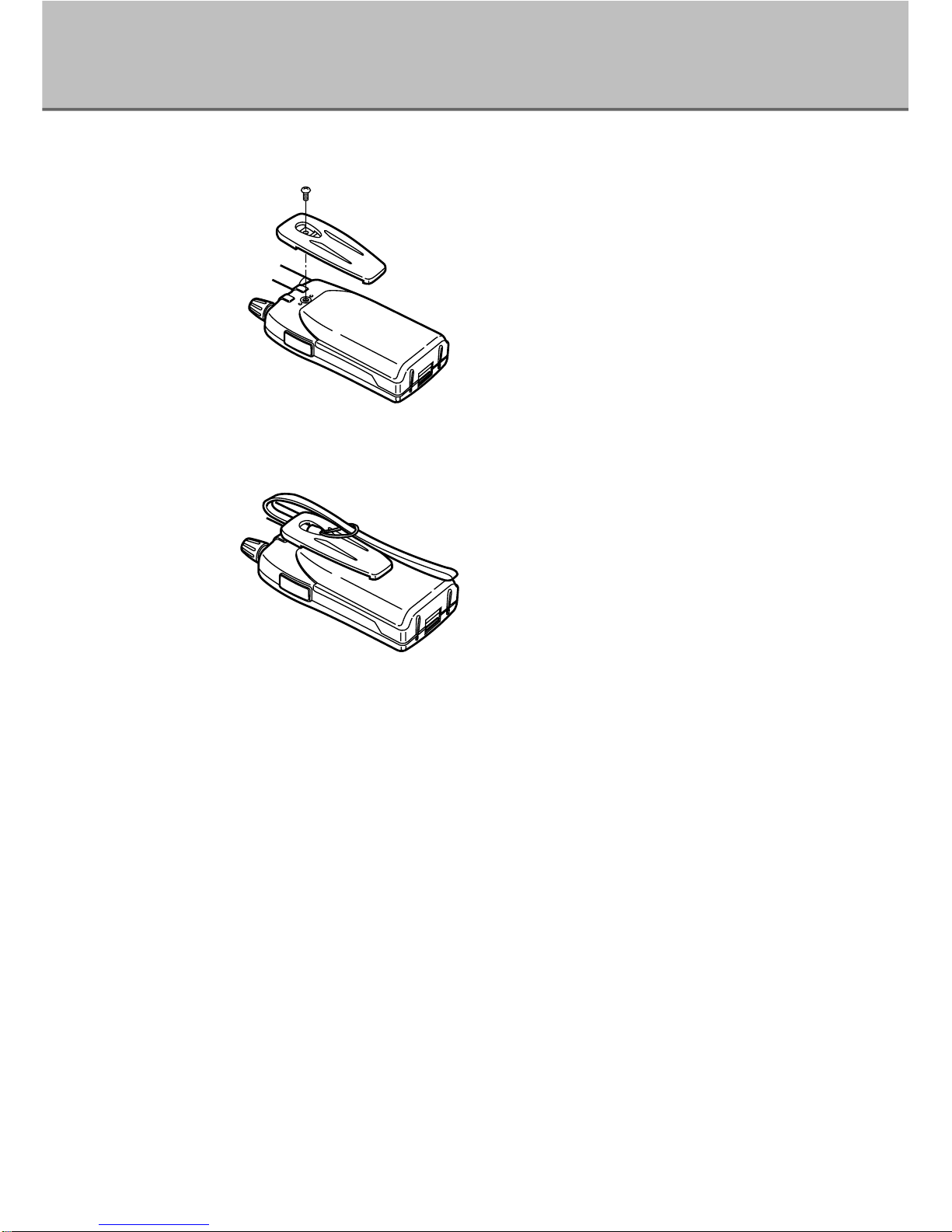
Attaching the Belt Clip ············································································12
Attaching the Hand Strap ·······································································12
Chapter1 Names and Functions of Parts
External View ································································································13
Front········································································································13
Top··········································································································13
Side·········································································································14
Keyboard······································································································15
Display··········································································································16
Chapter2 Basic Operation
Power Switch ································································································17
Adjusting the Audio Volume ·········································································17
Adjusting the Squelch···················································································18
Adjusting the Squelch Level ···································································18
Monitor Function ·····················································································19
Mute Function ·························································································19
Operating Mode····························································································20
Switching Modes·····················································································21
Setting the Frequency···················································································22
In VFO Mode···························································································22
In Preset Mode························································································22
In Memory Mode·····················································································23
Memory Function··························································································23
Types of Memory ····················································································23
Programming a Channel·········································································24
Erase the Channel···················································································25

4
Scan Function·······························································································26
VFO Scan································································································27
Program Scan ·························································································27
Preset Scan·····························································································28
Memory Scan··························································································28
Setting the Tuning Step ················································································30
Memory Skip·································································································31
Chapter3 Convenient Functions on DJ-X3
Descrambling ·······························································································32
Bugging Detector ·························································································33
Keylock·········································································································35
Battery Indication··························································································35
Resetting·······································································································36
How to Reset Partially ·············································································36
How to Reset All······················································································36
The Set Mode Function·················································································37
Setting Each Item····················································································37
ATT (Attenuator) Function·······································································38
Setting the Antenna·················································································38
Selecting the Modulation Mode ······························································39
Selecting from Stereo and Monophonic ·················································40
Setting Bugging Detector Sensitivity ······················································40
Setting Bank Link ····················································································41
Lamp Function························································································42
Setting the Scan Mode (Timer Scan/Busy Scan)····································42
APO (Auto Power Off) Function ······························································43
BS (Battery Save) Function·····································································44
Overwrite Memory Setting·······································································44
PRIO (Priority) Watch Function ·······························································45
Beep Function·························································································45
Setting Operation in the Monitor and Mute Function ······························46
Setting Operation of the MONI key·························································46
Cloning··········································································································47
Chapter4 Appendix
Troubleshooting····························································································50
Specifications ·······························································································51

5
Features
The DJ-X3 is a wide band communication receiver which has various functions
in a small package.
Easy operation with a simple key arrangement allows you to access a wide
range of communications.
The DJ-X3 has the following features.
TypesofMemory
The DJ-X3 has different types of memory functions.
For instance, except Memory channel for regular
calling up usage, "Program channel" which allows
you to specify upper and lower limit of range for
scanning frequency, "Priority channel" which allows
you to receive two programmed frequencies
alternately, and so on.
For more information, see
"Memory Function." (P.23)
TypesofScanning
The DJ-X3 has several types of scanning functions,
which search for receiving signals quickly and
easily. It allows you to select a variety of scanning
operations, such as "Memory scan", "Program scan",
and so on.
For more information, see
"Scan Function." (P.26)
For more information, see
"Bugging Detector." (P.33)
BuggingDetector
The DJ-X3 can detect a frequency which may be
used for bugging. When a listening microphone is
found, the DJ-X3 alerts you with a display and a
warning sound.
For more information, see
"Descrambling." (P.32)
Descrambling
The DJ-X3 can return scrambled voice
transmissions to normal voice reception.

6
Tested to Comply
With FCC Standards
FOR HOME OR OFFICE USE
Information in this document are subject to change without notice or obligation.All
brand names and trademarks are the property of their respective owners. Alinco
cannot be liable for pictorial or typographical inaccuracies. Some parts, options
and/or accessories are unavailable in certain areas. Changes or modifications not
expressly approved by the party responsible for compliance could void the user's
authority to operate the equipment.
Copyright 2000 All rights reserved. No part of this document may be reproduced,
copied, translated or transcribed in any form or by any means without the prior
written permission of Alinco, Inc., Osaka, Japan. English Edition Printed in Japan.
NOTICE
This equipment has been tested and found to comply with the limits for a
Class B digital device, pursuant to part 15 of the FCC Rules. These limits are
designed to provide reasonable protection against harmful interference in a
residential installation. This equipment generates, uses, and can radiate radio
frequency energy and, if not installed and used in accordance with the
instruction manual, may cause harmful interference to radio communications.
However, there is no guarantee that interference will not occur in a particular
installation. If this equipment does cause harmful interference to radio or
television reception, which can be determined by turning the equipment off
and on, the user is encouraged to try to correct the interference by one or
more of the following measures:
- Reorient or relocate the receiving antenna.
- Increase the separation between the equipment and receiver.
- Connect the equipment into an outlet on a circuit different from that to which
the receiver is connected.
- Consult the dealer or an experienced radio/TV technician for help.

7
Precautions
No warranty is made on the effectiveness of the "Bugging Detector" function.
The function should be considered experimental and for educational or
entertainment use.
Use of the descrambling function may not be permitted in certain jurisdictions.
Check with the regulations that apply in your area before using.
Request and Agreement
·This product is manufactured and shipped under strict quality control.
However, in some rare instances, if questionable or doubtful points are found,
please notify the store where you purchased the product.
·Since this product is a wide band communication receiver, its internal
oscillation sometimes block a signal, or defect an internal signal (sometimes
referred to as a "birdie.") These symptoms are not a malfunction.
·The contents of this instruction manual may change without notice.
DANGER
Improper product handling may cause cracking, fire, smoke, performance loss
or other troubles. Observe the following precautions in usage.
1. Do not disassemble or modify this product.
2. Do not insert any metal objects into the charger terminal.
3. Avoid using or storing the product in excessively hot environments, i.e.
inside hot cars or outdoors in scorching heat. Also, avoid highly humid and
dusty places.
4. Do not drop the product or subject it to strong shocks.
5. Use the exclusive recharger EDC-105 to charge the DJ-X3.

8
Accessories
Open the box and check that the following accessories are included.
·Instruction manual ·Antenna
·Belt clip (with one screw) ·Hand strap
·Battery case (EDH-31S) ·Battery recharger (EDC-105)
·AC adapter (EDC-92) ·Warranty
·Frequency data list
·NiMH (Nickel Metal Hydride) battery pack (EBP-52NS)
■Connecting the Antenna Connect the antenna to the SMA
antenna connector at upper left
corner.
Hold the antenna by its base, and
turn it clockwise until it stops.
To disconnect the antenna, turn it
counter-clockwise.
■Attaching the Battery Case
· How to attach the battery case
Align with the grooves on the transceiver, and
slide in the direction of the arrow until it clicks.
· How to detach the battery case
Push down the catch, and pull out the battery
pack or case free of the transceiver.
Tip
Attaching/detaching the NiMH battery pack is
the same way as the battery case.
Catch
Groove

9
■Loading the Batteries Load three AA batteries in the battery
case in the "+" and "-" orientation
marked at the bottom of the case.
Caution!
· Do not use NiCad AA batteries on the market.
· Use new batteries of the same type and brand.
· Use high capacity of alkaline batteries.
■The NiMH Battery Pack
Caution!
· The battery pack is not charged when shipped.
It must be charged before use.
· It takes 10 hours maximum to fully charge the
battery pack with the EDC-105.
· Charging should be conducted in a temperature range of 0 to 40°C. (32 to
104°F)
· Do not modify, dismantle, incinerate or immerse the battery pack in the
water as this can be dangerous.
· Never short-circuit the battery pack terminals, as this can cause damage
to the equipment or lead to heating of the battery which may cause burns.
· Unnecessary prolonged charging (overcharging) can deteriorate battery
performance.
· The battery pack should be stored in dry place where temperature is from
-20 to +45°C. (-4 to +113°F)
Temperatures outside this range can cause the battery liquid to leak.
Exposure to prolonged high humidity can cause corrosion of metal
components.
· Normally, the battery pack can be charged up to 500 times. However, the
battery pack can be considered dead if the period of use drops off
markedly despite the pack being charged for the aforementioned charging
time. When this happens, a new pack should be used.
· Do not dispose the battery pack due to environmental protection. At the
end of its useful life, check with your local solid waste officials for details
on recycling options or proper disposal in your area. You may also
contact to our office.
EBP-52NS (3.6V-500mAh)
About 10 hours
Battery Pack Type Charging Time

10
■Prevent Short Circuiting the Battery Pack
Be extra cautious when carrying the
battery pack; short-circuiting will
produce surge current possibly
resulting in fire.
Terminals
DON'T carry with
metals of any type,
e.g. chains.
Do enclose inside a non-conductive enclosure.
(bags or handkerchief made only of non-
conductive material)
DON'T carry the
NiMH battery pack
inside bags of metal
plated interior.
Do protect by
spreading a non-
conductive sheet to
place on a flat surface.
DON'T place in the
proximity of metals or
conductives, e.g. nails,
chains.

11
■Battery Recharger
· Recharging with the EDC-105 1. Mount NiMH battery pack on the
transceiver. (The NiMH battery
pack itself is also mountable on
the battery recharger.)
2. Connect AC adapter plug to the
battery recharger.
3. Select the position 1 to 3 with the
lever on the recharger and adjust
the battery pack to fit with it.
(According to a type of battery
pack, position of the lever
changes.)
4.Set the battery pack to the
recharger making contact with
terminals on the rear side of the
transceiver and those on the
recharger side.
5. Connect the power plug to the AC
outlet.
6. The red light on the recharger
goes on and starts to recharge.
(While connecting to the AC outlet,
the charge status is maintained.)
Caution!
· When battery temperature exceeds a certain level, protective function
operates automatically and turns off the charge status. (The red light goes
off.)
In that case, unplug the recharger and dismount the transceiver or the
battery pack immediately. After removing the cause, then use the battery
recharger.
· Turn the transceiver power off before recharging the battery pack.
· Disconnect the EDC-105 from the outlet while not using it.
· Never charge battery packs of other manufactures with this charger.
· The required recharging time depends on the condition and model of a
battery pack, but it may take at most 10 hours. Refer to the instruction
manual of the battery pack.
· Never short-circuit the recharging terminals of this recharger with metal
objects, etc. The charger can be damaged.
· The ECD-105 does not work when the voltage from the wall outlet is
extremely low.
AC adapter plug
Terminals
(rear side)
Terminals
on the rechager
Lever(1〜3)
Power plug
1
2
3

12
■Attaching the Belt Clip Attach the belt clip on the rear side of
the transceiver with an included
screw. Make sure it is screwed
properly.
■Attaching the Hand Strap Attach the hand strap through a ditch
between the belt clip and the
transceiver as shown in the
illustration on the left.

1
Chapter Names and Functions of Parts
13
1
Names and Functions of Parts
External View
■Front
■Top
Antenna connector
For connecting the included antenna.
(P.8)
Earphone jack
For connecting of an earphone.
Dial, [VOL/SQL(SET)] key
Use this dial to change frequency and
various settings. When press it down,
change the volume level and settings of
squelch, or select options in Set mode.
Display
Displays the frequency and other infor-
mation. (P.16)
Speaker
Thin built-in speaker
Keyboard
For changing the mode and various set-
tings. (P.15)
POWER
SCAN
SCRT
V/P/M
MW
BANK
WIDE BAND
COMMUNICATION RECEIVER
DJ-X3
1M/10M

14
1
Names and Functions of Parts
■Side
DC-IN
Terminal for connecting an external DC
power supply.
INDC
[FUNC/ENTER] key
Use this key to set and execute several
settings. Besides, hold this key down for
about one second, key-lock function is
on. (P.35)
[MONI(ST/SK)] key
While holding this key down, squelch
temporarily opens. Besides, use for
Mute function. (P.19)
ENT
KL
ST SK
MONI
FUNC
Caution!
When use an antenna on the market, set a ground for the antenna which
should be different from the one for an external power.

15
1
Names and Functions of Parts
Keyboard
"F" appears on the display when you press the [FUNC/ENTER] key
Turn the power on/off.
Executes scanning. (P.26)
When "F" is displayed, used for Descrambling.
(P.32)
Switches the operating mode. (P.21)
When "F" is displayed, programs and clears the
Memory channels. (P.24,25)
Switches the Preset and Memory mode. (P.22,23)
In VFO mode, switches a unit for
increasing/decreasing frequency by one click
of the dial.
Key Function
[POWER] key
[SCAN (SCRT)] key
[V/P/M (MW)] key
[BANK(1M/10M)]key
①
②
③
④
①
②
③
④
POWER
SCAN
SCRT
V/P/M
MW
BANK
WIDE BAND
COMMUNICATION RECEIVER
DJ-X3
1M/10M

16
1
Names and Functions of Parts
Display
In the illustration below, all indicators are displayed.
From ⑫to ⑯are not displayed on this transceiver.
Descriptions
Appears when you press the [FUNC/ENTER] key.
Flashes when displaying over 1000MHz frequency. (Indicates a digit
of 1000MHz.)
Indicates the modulation mode. Appears "W" when WFM radio is
selected and "A" when AM radio is selected. When FM radio is
selected, nothing appears.
Appears when executing Memory skip.
Appears when the keys are locked.
Appears when the battery is exhausted.
Displays the bank No. (left one digit) and the channel No. (right two
digits) of Programmed memory.
Displays the frequency and value of various settings.
Appears when using the Bugging Detector.
Flashes when Descrambling.
Appears when the Attenuator is ON.
Displays the relative signal strength.
①
②
③
④
⑤
⑥
⑦
⑧
⑨
⑩
⑪
W
SKIP
ATT
VOX
A
F T SQSQ DCSDCS
75
50
25
B
①
⑩
⑯
⑮
⑪
⑦
⑧
⑨
②⑫⑬
③④⑤⑥
⑭

2
Chapter Basic Operation
17
2
Basic Operation
Power Switch
Hold the POWER switch down for a second. "HELLO" will appear on the
display. (The indication may be different from the illustration below depending
on the version: North America or Europe.)
To turn the power off, hold the POWER switch down until the indication
disappears.
Adjusting the Audio Volume
1Press the [VOL/SQL (SET)] key. (dial)
"voL" will appear on the display.
2Adjust the audio volume by rotating the dial.
There are 31 levels of audio volume. (00-30) As the value increases, the
audio becomes louder.
3Press the [FUNC/ENTER] key.
Be back to normal mode.
If the DJ-X3 makes no sound...
When the squelch closes or the Mute function is activated, the DJ-X3 does
not make sound even if you increase the value of audio volume. For more
information, see "Adjusting the Squelch Level" (P.18) and "Mute Function." (P.19)
POWER
3
1
2
[POWER]key
POWER
SCAN
SCRT
V/P/M
MW
BANK
1M/10M

2
Basic Operation
18
Adjusting the Squelch
The squelch silences the DJ-X3 except for signals above a certain level.
Squelch eliminates noise when the DJ-X3 receives less than a certain level.
"To unmute the squelch" means that the DJ-X3 receives a signal and
reproduces the sound.
Conversely, "to close the squelch" means that the DJ-X3 does not generate
audio because of insufficient signal level.
■Adjusting the Squelch Level
You can specify the signal level at which the DJ-X3 unmutes by adjusting the
squelch level.
1Press the [VOL/SQL (SET)] key (dial) twice.
(When "voL" is on the display, press it once.)
"SqL" will appear on the display.
2Adjust the squelch level by rotating the dial.
There are 11 squelch levels. (0-10) A higher squelch level requires a
stronger signal to unmute the squelch.
3Press the [FUNC/ENTER] key.
Be back to normal mode.
Tip
To keep the squelch open, set the squelch level to 0.
POWER
3
1
2

19
2
Basic Operation
■Monitor Function
The Monitor function temporarily unmutes the squelch. This is useful when the
desired signal is weak or intermittent. This function is activated when the status
of the [MONI(ST/SK)] key is set as Monitor function in the Set mode. For more
information, see "Setting Operation of the MONI key." (P.46)
There are two options in the Monitor function: PUSH and HOLD. Both two
options open squelch, and "B" appears on the display when press the
[MONI(ST/SK)] key.
· PUSH: Squelch unmutes while holding the [MONI(ST/SK)] key down. When
release the key, squelch goes back to be normal as you set before.
· HOLD: Squelch unmutes and remains the status once press the
[MONI(ST/SK)] key. Press the key again, then Monitor function is off,
and squelch goes back to be normal as you set before.
Switch the mode between PUSH and HOLD in the Set mode. For more
information, see "Setting Operation of the MONI key." (P.46)
■Mute Function
This function mutes sound. Even when squelch opens, this function makes
sound off, and while it is activated, beep sound does not go off either. This
function is activated when the status of the [MONI(ST/SK)] key is set as Mute
function in the Set mode. For more information, see "Setting Operation of the
MONI key." (P.46)
There are two options in the Mute function: PUSH and HOLD, as well. Both two
options execute Mute function, and "B" appears on the display when press the
[MONI(ST/SK)] key.
POWER
SCAN
SCRT
V/P/M
[MONI(ST/SK)]key

2
Basic Operation
20
· PUSH: Mute function is on while holding the [MONI(ST/SK)] key down. When
release the key, the function is off and receiving signals and beep
sound unmute.
·HOLD:Mute function is on and it remains the status once press the
[MONI(ST/SK)] key. Press the key again, then the function is off and
receiving signals and beep sound unmute.
Tip
Select either Monitor function or Mute function.
The preparation for receiving a signal has been finished. Now, try to adjust the
frequency and receive a signal.
Next section explains the three operating models of the DJ-X3.
Operating Mode
The DJ-X3 has three operating modes; VFO mode, Preset mode, and Memory
mode.
VFO mode ···································VFO mode allows you to change the
frequency by the dial.
Preset mode································The frequencies of AM radio, FM radio, and
TV have been set already and you can call
up among them.
Memory mode ·····························You can call up and receive a previously
programmed frequency.
Tip
To program memory, see "Memory Function." (P.23)
B
POWER
SCAN
SCRT
V/P/M
[MONI(ST/SK)]key

21
2
Basic Operation
■Switching Modes
Every press of the [V/P/M (MW)] key changes the operating mode as shown
below.
Tip
When nothing is programmed in Memory mode, Memory mode is skipped and
switches between VFO mode and Preset mode in turn.
Preset mode Memory mode
VFO mode
V/P/M
MW
V/P/M
MW
V/P/M
MW

2
Basic Operation
22
Setting the Frequency
■In VFO Mode
Rotating the dial increases or decreases frequency for a tuning step.
To increase/decrease the frequency by 1MHz-step, press the [BANK(1M/10M)]
key one time and rotate the dial one click each.
To increase/decrease the frequency by 10MHz-step, press the
[BANK(1M/10M)] key once again and rotate the dial one click each.
In 1MHz and 10MHz mode, each digit of 1MHz or 10 MHz number flashes.
■In Preset Mode
1Select a band by pressing the BANK key.
Every press of the [BANK(1M/10M)] key changes the band as shown below:
AM radio →FM radio →TV →AM radio...
2Increase/decrease the frequency by rotating the dial.
Tip
"A" appears on the display when selecting AM radio, and "W" appears when
selecting TV. However, nothing appears when selecting FM radio. Also,
frequency displays when AM/FM radio is selected and channel displays when
TV is selected.
W
POWER
SCAN
SCRT
V/P/M
MW
BANK
1M/10M
1
2
Adjustthefrequency
Increases/decreases
by1MHz-stepwithonepress,
by10MHz-stepwithdoublepress.
POWER
SCAN
SCRT
V/P/M
MW
BANK
1M/10M
Other manuals for DJ-X3
2
Table of contents
Other Alinco Receiver manuals

Alinco
Alinco DR-135 User manual

Alinco
Alinco DJ-X10 User manual

Alinco
Alinco DR-135 Mk III User manual

Alinco
Alinco DR-150T User manual

Alinco
Alinco DJ-X2000 User manual

Alinco
Alinco DJ-X7E User manual

Alinco
Alinco DJ-X2 E User manual

Alinco
Alinco DX-R8T User manual

Alinco
Alinco DJ-X10 User manual

Alinco
Alinco DJ-X30T User manual

Alinco
Alinco DJ-X3 User manual

Alinco
Alinco DJ-X2000T User manual

Alinco
Alinco DR-135 User manual

Alinco
Alinco DJ-X1 User manual

Alinco
Alinco DJ-180 User manual

Alinco
Alinco DJ-X2000 User manual

Alinco
Alinco DJ-X1 User manual

Alinco
Alinco DJ-X3 T User manual

Alinco
Alinco DJ-191 User manual

Alinco
Alinco DJ-X7E Installation guide