Alinking ALC-9751 User manual

ALC-9751/9751W
3GPP Professional Revolving PT
Internet Camera
User’s Manual
Version 1.0

Content
Content...........................................................................................................................1
Packaging Contents........................................................................................................4
System requirements......................................................................................................5
Introduction....................................................................................................................6
Features and Advantages................................................................................................6
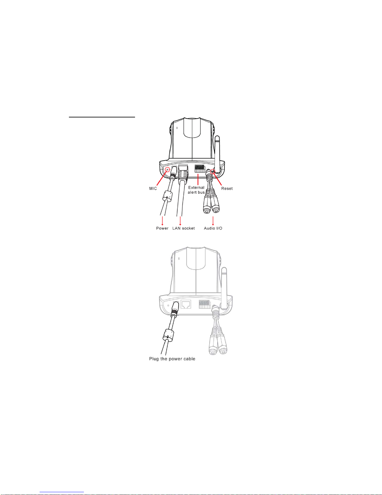
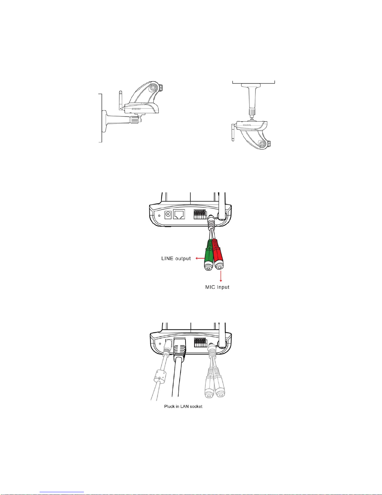
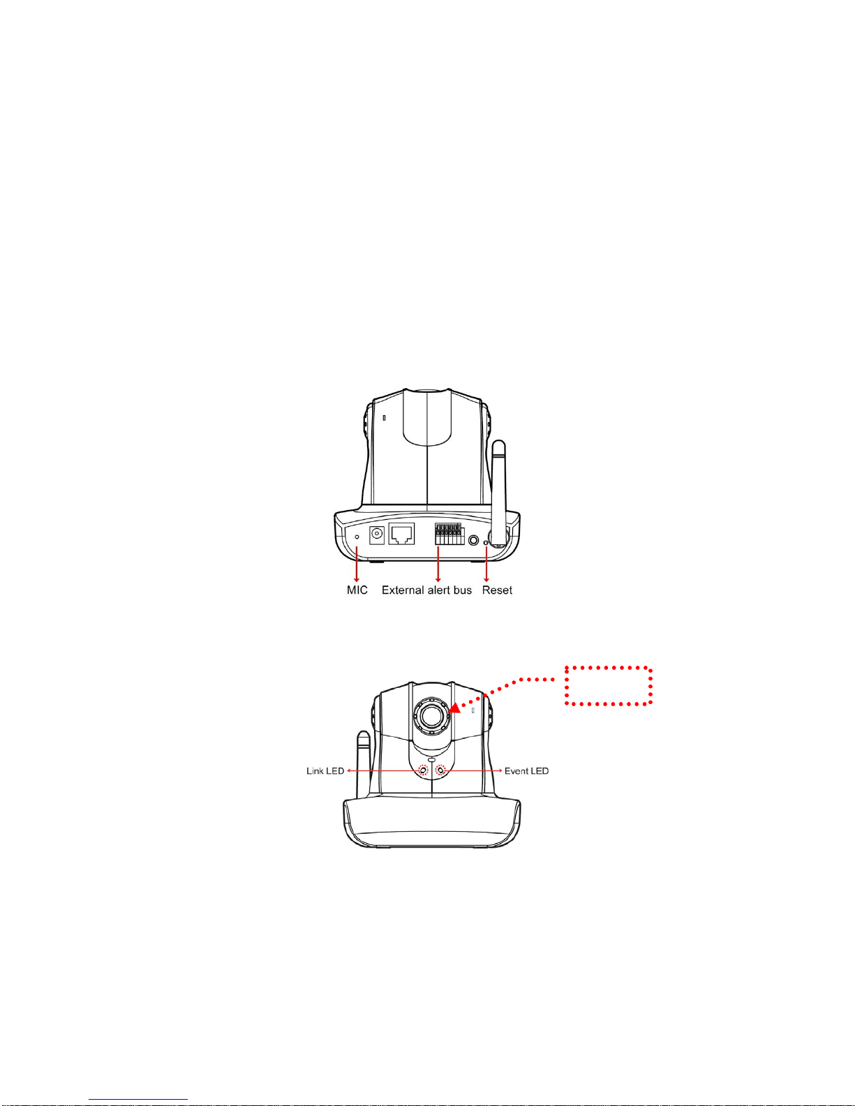
System Instructions........................................................................................................7
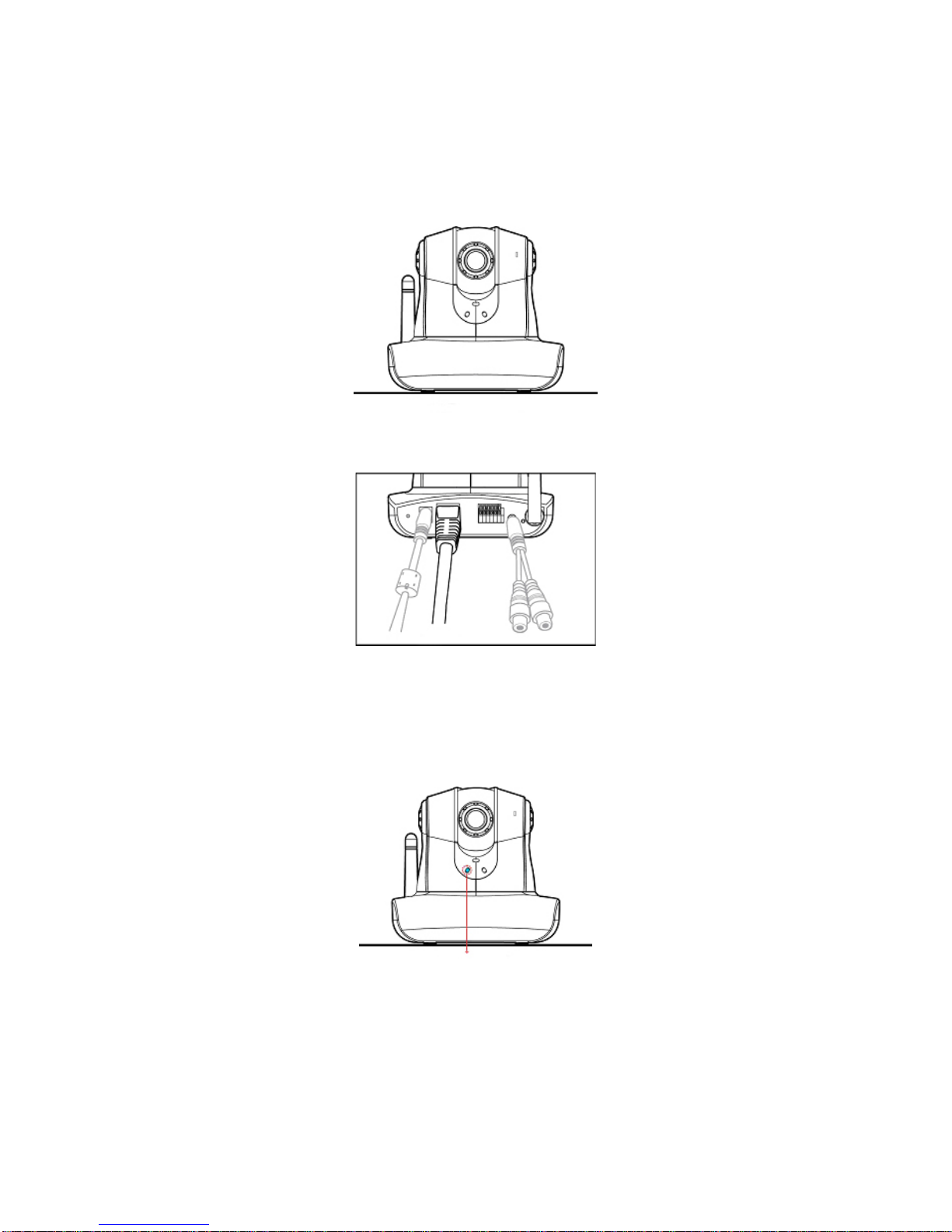
Hardware Installation...................................................................................................10
Camera Setting.............................................................................................................11
Camera Setting from a Router .....................................................................................13
Change the Internet Explorer Setting...........................................................................14
Enter the Main Page.....................................................................................................15
Camera Main Page.......................................................................................................17
System setting..............................................................................................................27
Basic Setting ................................................................................................................27
System .................................................................................................................27
Video/Image........................................................................................................28
Audio...................................................................................................................35
User......................................................................................................................36
Network...............................................................................................................38
Network........................................................................................................38
Wireless........................................................................................................39
Streaming.....................................................................................................44
PPPoE ..........................................................................................................45
DDNS...........................................................................................................47
UPnP............................................................................................................48
SMTP Server................................................................................................50
Samba...........................................................................................................51
Date/Time............................................................................................................54
IP Filter ...............................................................................................................55
Application Setting ......................................................................................................56
Event....................................................................................................................56
Motion Detection................................................................................................63
Firmware upgrade .............................................................................................64
Factory Default...................................................................................................66
2

Reboot .................................................................................................................68
Attachment A: External Alarm.....................................................................................69
Attachment B: Bandwidth Estimation.........................................................................69
Attachment C: Troubleshooting and FAQs..................................................................72
3

Packaging Contents
The UNC-9751 PT Internet Camera is provided with the following accessories. Please
contact your dealer if any one of the following is missing.
1. ALC-9751 PT Internet Camera 2. 12V DC power cable
3. Tripod 4. AV Y cable
5. Quick guide 6. CD
4

System requirements
ALC-9751/9751P/9751W PT Internet Camera
Internet Environment
LAN 10/100M Ethernet
Wireless LAN 802.11b or 802.11g
Monitor System Requirements
OS support Windows 2000 Professional SP4, XP Home SP2
Browser support Internet Explorer 6.x or later
Hardware CPU: Pentium 4 2.4 GHz or later
Memory: 256 MB (512 MB recommended)
VGA card resolution: 800 x 600 or higher
5

Introduction
The ALC-9751/9751P/9751W 3GPP Professional Revolving PT Internet Camera is a
multi-functional stand-alone PT Internet Camera that can connect to Ethernet, LAN,
or any broad-band networks. Unlike traditional CCTV cameras, the
UNC-9751/9751P/9751W PT Internet Camera has a built-in CPU and webpage server
to provide users with a mechanism for home security or remote office monitoring
applications. The UNC-9751/9751P/9751W PT Internet Camera supports 3GPP
real-time video streams that allow you to control the home or office environment
using a 3G mobile phone. The ALC-9751/9751P/9751W PT Internet Camera is easy
to install and use. The built-in webpage server enables you to control the security and
property of your home easily when you go abroad.
Features and Advantages
The UIC ALC-9751 3GPP Professional Revolving PT Internet Camera is a
stand-alone PT Internet Camera. It can operate smoothly without the need to install
additional software or hardware. All you need is a PC that is equipped with IE
browser (6.0 or above) and connect the Internet Camera to the network to monitor the
pre-set places remotely. The UIC ALC-9751/9751P/9751W 3GPP Professional
Revolving PT Internet Camera provides you with protection of your personal, home,
and property security.
The UIC ALC-9751 3GPP Professional Revolving Internet Camera features:
z1/3"CCD color image sensor to ensure clear and vivid imaging effect;
zMPEG4/MJPEG dual video compression mode and dual coding mechanism for
multiple applications;
zSupport of 3GPP real-time video streams that allow you to control home or
office environment using a 3G mobile phone;
zAuto-pan camera with 270°(horizontal) and 135°(vertical) rotation angles and a
maximum of 16 pre-set scan points;
zBuilt-in smart motion detection to monitor abnormal situations automatically and
transmit real-time trigger command actively as preset;
zBuilt-in webpage server that allows easy control via the Internet;
zDynamic IP domain name support for use of the product at locations where fixed
IP is not available;
zAccess setting by level to ensure security and protection of life and properties;
zElegant style suitable for homes, studios, offices, clinics, and retail shops; and
zOptional Ethernet Internet camera (ALC9751P) and Wireless Version
(ALC-9751W) to meet your special requirements.
6

System Instructions
1. DC power cable: The DC input connector has a socket to connect the product to a
power source.
2. Ethernet connector: A RJ-45 connector is provided for connection to the 10Base-T
Ethernet cable or 100 Base-T High Speed Ethernet cable. This port can
automatically detect or coordinate the transmission rate of the network.
3. Use a video/audio output cable for external video/audio transmission if required.
Wiring of the product
DC Power
Plug the power cable in the power socket on the product.
Tripod
The product can be fixed on the wall (Fig. 1) or hung from the ceiling (Fig. 2).
When using the attached plastic anchor and screws to fix the product, make sure that
no steel bars or power cables exist behind the position where the product is to be fixed.
Some walls or ceilings may not be strong enough to support the tripod and the product.
Pay attention during installation to avoid injury that might be brought about due to
falling of the product.
7

Note: The horizontal angle is important when you hang the product from the ceiling. Excessive
inclination may bring about abnormal rotation of the camera lens.
Fixed on a wall (Fig. 1)
Fixed on a ceiling (Fig. 2)
Audio/Video Output
Plug the AV converter in the audio/video output.
The yellow RCA female plug is for video output.
The white RCA female plug is for audio output.
LAN Socket
Insert your LAN cable in the LAN socket.
8

External alert bus (DI/DO)
For more information about DI/DO, refer to Attachment A.
Reset to factory settings
After turning on the machine, press in this hole for 5 seconds using a sharp object to
reset to factory settings.
Built-in microphone
The product is provided with built-in microphone pickup function. Don't block this
hole if you want to use this function to acquire the best audio response.
Link LED and Event LED
1. Link LED: The green LED lights up when you transmit images after turning on
the machine.
2. Event LED: The green LED flashes when motion or alert detection is
implemented after you turn on the machine.
Focus knob
You can rotate the focus knob clockwise or anticlockwise to acquire the sharpest
image.
Focus knob
9

Hardware Installation
You can install the product on your desk or use the attached tripod to hang it from the
wall or ceiling. (The product is provided with image flip function. Refer to the
“Control Panel” for more information.)
Confirm the position for installation of the camera
1. Connect to the LAN cable
Plug one end of your LAN cable in the LAN socket on the back of the camera and
connect the other end to the network that you want to access to.
Pluck in LAN socket
2. Connect to the power source
Plug one end of the attached power cable in the power socket of the product and
connect the other end to the AC power source. When the product has been connected
and turned on, the Pan/Tile camera turns to the original point automatically and the
LED: Event status lights green. When any link to the network is detected, the LED:
Link status flashes green.
Connect to the power supply and check that the LED functions normally.
Note 1: You can install the product quickly with reference to the quick guide attached to the
product.
You can specify three LED statuses by setting: 1.ON; 2.OFF; 3.Flash. For more information about
setting of LED status, refer to the “System Setting”.
Note 2: Don't install the camera at an oblique angle to avoid disrupted operation of the machine.
10

Camera Setting
After the hardware has been installed, insert the attached CD in the computer and
execute IP FINDER.EX following the steps below to search and change the IP
address of the camera.
1. Start the machine.
Execute the IP Finder.exe from the attached CD.
2. Search the camera (Search)
Search the product from your LAN. The factory IP setting 192.168.0.20 appears
on the screen.
1. Click Search to
find the IPCAM on
the LAN.
3. Changing the IP address and related settings for the network environment
When you find the camera, click it and the settings appear on the right side.
Change the settings for the new network environment you need.
2. Enter the settings for the
new network environment
you need.
※ You must enter new settings in the IP, Netmask and Gateway fields and keep
the settings in other fields unchanged.
4. Submit data (Submit)
Click Submit to validate new settings.
11

3. Click Submit to
validate new settings.
5. Confirmation
When all changes have been confirmed, click Exit to quit.
4. When all changes
have been confirmed,
click Exit to
q
uit.
Notes:
1. The IP FINDER can only find the IP addresses of the cameras that share the same hub on the LAN.
For information about finding IP addresses on the Internet, refer to the “DDNS Setting”, or “UpnP
Setting”.
2. All UIC camera/network server products can be found and changed using the IP FINDER
software.
3. When the IP FINDER software cannot be executed, check your antivirus software or firewall to
remove the block.
4. Field description: You can give a name to your camera (such as “PT_IP” or “PT-IP”). No spaces
allowed (such as “PI IP”).
You can change the settings for IP, Gateway Address and Network Mask to meet the requirements
of your network environment. The product uses HTTP Port1 and does not support Port2 settings.
MAC: Factory default network identity of the machine.
12

Camera Setting from a Router
You can use DHCP when you want to use the camera on the Intranet (LAN). However,
the IP must be set to fixed when you want to use the camera on a WAN. For this
application, it is required to set up the function of the virtual server on the ADSL
router. Follow the steps below to complete the setting:
1. Enter the camera setting page to set a fixed IP. (Refer to the “Network Setting”.)
Ex.: 192.168.0.49
2. Enter the ADSL router main setting page. Ex.: Zonet ADSL router
3. Enter the Virtual Server setting page.
a. Set “mapping of HTTP Port (80) to 192.168.0.49 ”.
b. Restart ADSL router.
When completing the setting, you can operate the camera from the WAN IP Address
via the ADSL router.
The Virtual Server setting screen of the Zonet ADSL router
Note: The virtual server setting screen is not the same for all ADSL routers. Refer to the manual of the
ADSL router you purchased for more information about the setting.
13

Change the Internet Explorer Setting
The product uses ActiveX Control to play image and sound on your PC and the
ActiveX Control application software will be downloaded to your PC when you
connect it to the Internet. To ensure successful download of the software, the Internet
Explorer "security settings" must be changed accordingly. Make sure that the security
level is set to Level II, the commonly used default security level.
Steps:
Open the IE browser ÎTools ÎInternet Options ÎSecurity ÎCustom Level
Check that the
security level is
Level II.
Check the security setting
Note: This product supports IE 6.0 or above.
14

Enter the Main Page
1. Open the IE browser and key in the IP address of the product.
Key in the IP address of the camera
When the login screen
appears, key in "root" in
the User Name and
Password fields. Click
OK.
Camera login screen
2. Key in the default “username” and “password”.
User Name: root
Password: root
You can access the camera as an administrator by default and set up for other
users or privileges from the “Basic Settings” -> “User”.
3. Installation of Internet Explorer ad-hoc components
When the username and password are confirmed, a control setup screen pops up
under the IE address bar. Click “Install ActiveX Control” to install the controls.
15

Click “Install
ActiveX Control”.
Setup prompt screen
4. The security warning screen appears. Click "Install".
The ActiveX Control is named "UIC ActiveX Control". This software is owned by
UIC and well certified. You can use it without any doubts about its validity.
Click “Install”.
5. When ActiveX Control is installed successfully, you can see the camera image
and interface.
Camera main page and image
16

Camera Main Page
Descriptions:
Source: Information bar
1. Format: resolution of the current video stream
2. FPS: FPS of the current video stream
3. BitRate: bandwidth per second of the current video stream
Brand Logo – Click to access the latest information from our
website.
Product name
Image area
Attention: Please change the streaming setting to HTTP if nothing appears in the image area.
17

Control panel
1. Camera direction: controls the direction of the camera (up, down, left, right,
home position).
Direction control.
2. Camera speed: controls the rotation speed of the camera from “1” (lowest) to
“7” (highest).
Rotation speed.
Speed 1 2 3 4 5 6 7
Angle/Sec. 3 20 40 60 80 100 120
18

3. Preset: presets the rotation points for the camera (16 points)
1. Click Set to enter the Preset Setting screen.
2. Enter the name of the
location.
3. Control the camera direction.
4. Click Update to exit.
5. Select the number you need and click Go. The
camera moves to the area automatically as set up
by the selected number.
19

4. Tour: enables/disables the tour mode of the camera.
The rotation points of the camera must be set up in advance.
1. Click Set to enter the Tour Setting screen.
3. Dwelling time (sec.) at each tour point.
2. Name the tour. You can set
up 5 tour groups at
maximum.
5. Click Update to Exit.
4. Select a preset location for the
camera.
6. Click Enable to activate the tour function.
20
This manual suits for next models
1
Table of contents
Other Alinking IP Camera manuals
Popular IP Camera manuals by other brands

Conceptronic
Conceptronic C54NETCAM2 installation guide

Digital ID View
Digital ID View IV-THB4200AT user manual

D-Link
D-Link SECURICAM NETWORK DCS-5300 user manual

Bosch
Bosch NBC-255-W Quick install

Live
Live LW2401AC2 SERIES quick start guide

Grandstream Networks
Grandstream Networks GXV3601 quick start guide