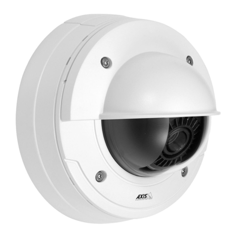
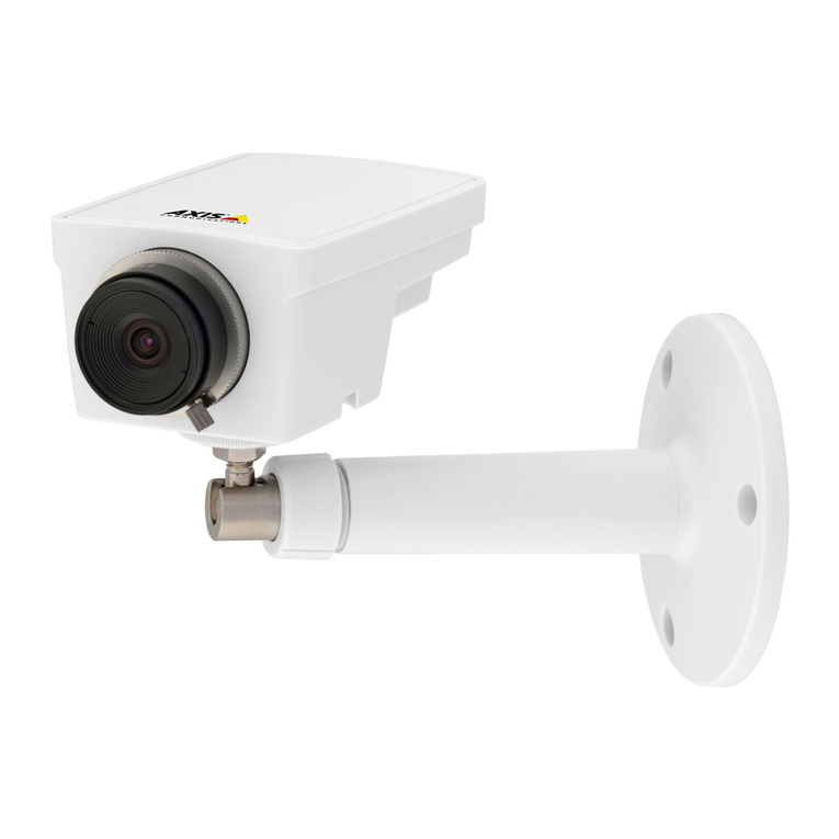
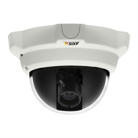
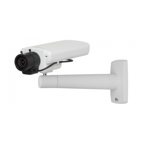
Axis Network Camera AXIS 221 User manual

ENGLISH FRANCAIS DEUTSCH ESPAÑOL ITALIANO
AXIS 221/223M
Network Camera
Installation Guide


AXIS 221/223M Installation Guide Page 3
ENGLISH
AXIS 221/223M Network Camera
Installation Guide
This installation guide provides instructions for installing the AXIS 221/223M Network
Camera on your network. For all other aspects of using the product, please see the
AXIS 221/223M User’s Manual, available on the CD included in this package, or from
www.axis.com
Installation steps
Follow these steps to install the AXIS 221/223M on your local network (LAN):
1. Check the package contents against the list below.
2. Connect the camera. See page 4
3. Set an IP address. See page 6
4. Set the password. See page 12
Package contents
Important!
Item Notes
Network Camera AXIS 221/223M
CS lens adaptor ring (AXIS 223M only)
Power adapter Country-specific
Camera stand Includes 1 adjustable screw mount, 1 base plate
Terminal block connectors 1 x 10-pin connector block for connecting external devices to the I/O terminal connector
1 x 3-pin connector block for connecting power to the 3-pin power connector
AXIS Network Video CD including Installation tool and other software, product documentation
Printed Materials • AXIS 221/223M Installation Guide (this document)
• Axis Warranty Document
To use the AXIS 221/223M outdoors it must be installed in a protective housing. For more information on
protective housings and other accessories, please visit www.axis.com

Page 4 AXIS 221/223M Installation Guide
Connections
1. Connect the AXIS 221/223M to your network using a standard network cable.
2. Connect power, using one of the 3 supported methods listed below:
• The supplied power adapter.
• Power over Ethernet (PoE) via the network cable. This will automatically be detected if
available via the network.
• The power connector block on the rear panel. See the illustration above.
Status
indicator
Zoom puller
(Tele/wide)
Focus puller
DC-Iris
Serial number
on underside
label
Power adapter
connector
10-pin I/O terminal
connector
Power
Power indicator
Network indicator
Reset/Control
button
connector
RS-232
connector
block
Network
(also PoE)
connector
DC-Iris
control cable
DC-Iris
control cable Power adapter
connector
RS-232
connector
Network
(also PoE)
connector
Power and network indicators
Reset/Control
button
Audio out
Audio in
connector
10-pin I/O terminal
AXIS 223M - Rear view
AXIS 221 - Rear view
AXIS 221/223M
Front view
Power connector
block

AXIS 221/223M Installation Guide Page 5
ENGLISH
10 pin I/O terminal connector block
3 pin power connector block
LED indicators
Pin Function Description
1 Output A On the external device output terminals (A and B), there is no distinction between
positive and negative (+ and -). The terminals use a photocoupler and are electri-
cally isolated from the other internal circuitry.
The maximum load should not exceed 100mA and the maximum voltage should be
not more than 50V DC. Note: Connecting AC to the output will damage the unit.
2 Output B
3DigitalInput1
Photocoupler Anode (+)
Photocoupled Input 1. Electrically isolated from the chassis and connectors, this
input can be supplied from an external DC voltage or the DC Power Input/Output
on pins 9 (DC+) and 10 (GND).
4DigitalInput1
Photocoupler Cathode (-)
5DigitalInput2
Photocoupler Anode (+)
Photocoupled Input 2. As above.
6DigitalInput2
Photocoupler Cathode (-)
7 RS-485-A (non-inverting) A half-duplex RS-485 interface for controlling auxiliary equipment.
8 RS-485-B (inverting)
9 DC+ Power Output This can drive the photocoupler inputs or other equipment. The output voltage level
is 3.0 V. A maximum current of 100mA can be sourced from the DC output.
10 GND Ground
LED Color Description
Network Green Steady for connection to 100 Mbit/s network. Flashes for network activity.
Amber Steady for connection to 10 Mbit/s network. Flashes for network activity.
Unlit No connection.
Status Green Shows steady green for normal operation. Note: The Status LED can be configured to be unlit dur-
ing normal operation, or to flash only when the camera is accessed. See the online help files for
more information. Go to Setup > System Options > LED settings
Amber Steady during startup, reset to factory default or when restoring settings.
Red Slow flash for failed upgrade.
Power Green Normal operation.
Amber Flashes green/amber during firmware upgrade.
GND DC+ Connect DC power (7-24V) on pins 1 and 2.
Connect AC power (10-24V) on pins 2 and 3.
AC AC
123

Page 6 AXIS 221/223M Installation Guide
Setting the IP address
The AXIS 221/223M is designed for use on an Ethernet network and must be assigned an IP
address to make it accessible.
Windows
Notes:
• The AXIS 221/223M has the default IP address 192.168.0.90
• If setting the IP address fails, check that there is no firewall blocking the operation.
See page 9 for other available methods for setting or discovering the IP address of the AXIS
221/223M e.g. in other operating systems.
AXIS IP Utility and AXIS Camera Management are the recommended methods for setting an IP address in Windows.
DHCP Server
in network
Operating system Recommended
method for:
AXIS IP Utility
See page 7
Optional Windows single camera /
small installations
AXIS Camera Management
See page 8
Optional Windows 2000/ XP Pro
Windows 2003 Server
multiple cameras /
large installations
Requirements
methods
Installation

AXIS 221/223M Installation Guide Page 7
ENGLISH
AXIS IP Utility
AXIS IP Utility automatically discovers and displays Axis devices on your network. The
application can also be used to manually set a static IP address. AXIS IP Utility is available on
the CD supplied with this product, or it can be downloaded from www.axis.com/techsup
Note that you must install the AXIS 221/223M on the same network segment (physical subnet)
as the computer running AXIS IP Utility.
Automatic discovery
1. Check that the AXIS 221/223M is connected to the network and that power has been
applied.
2. Start AXIS IP Utility. When the AXIS 221/223M appears in the AXIS IP Utility window,
double-click it to open the camera’s home page. To identify the camera, check for the serial
number in the list. The serial number is located on the product label.
3. See page 12 for instructions on how to set the password.
Set the IP address manually
1. Acquire an unused IP address on the same network segment your computer is connected
to.
2. Click the button Set IP address using serial number and enter the serial number and
IP address for the AXIS 221/223M. The serial number is located on the product label.
3. Click the Set IP button and follow the instructions.
4. Click View Home Page to access the AXIS 221/223M web pages.
See page 12 for instructions on how to set the password.
single camera / small installations
Notes:
Set the IP address using Axis IP Utility
within 2 minutes of starting the camera
AXIS IP Utility can be used to change a
dynamically set IP address to a static one
Notes:
Set the IP address using Axis IP Utility
within 2 minutes of starting the camera
AXIS IP Utility can be used to change a
dynamically set IP address to a static one
Notes:
Set the IP address using Axis IP Utility
within 2 minutes of starting the camera
AXIS IP Utility can be used to change a
dynamically set IP address to a static one

Page 8 AXIS 221/223M Installation Guide
AXIS Camera Management
AXIS Camera Management can automatically find and set IP addresses, show connection
status and manage firmware upgrades of multiple Axis video products. AXIS Camera
Management is available on the CD supplied with this product, or can be downloaded from
www.axis.com/techsup
Set the IP address
1. Check that the AXIS 221/223M is connected to the network and that power has been
applied.
2. Start AXIS Camera Management. When the AXIS 221/223M appears in the window,
double-click it to open the camera’s home page. To identify the camera, check for the serial
number in the list. The serial number is located on the product label.
3. See page 12 for instructions on how to set the password.
Set the IP address in multiple devices
AXIS Camera Management speeds up the process of assigning IP addresses in multiple devices
by suggesting available IP addresses from a specified range.
1. Select the devices that you want to configure (you can even select different models) and
click the Assign IP icon.
2. Enter the range of IP addresses, the subnet mask and default router that the devices can
use.
3. Click Find and the program will search in the specified range and suggest an available IP
address for each device.
multiple cameras / large installations

AXIS 221/223M Installation Guide Page 9
ENGLISH
Other available methods
This table shows all of the available methods for setting or discovering the IP address.
Notes:
•UPnP™, DHCP and Bonjour are enabled by default in the AXIS 221/223M.
• The AXIS 221/223M has the default IP address 192.168.0.90
• To view the admin pages for the DHCP server, please see the server’s own documentation. You may need to
contact your network administrator.
• If setting the IP address fails, check that there is no firewall blocking the operation.
•AXIS Dynamic DNS Service requires an Internet connection without HTTP proxy.
•Bonjour - applicable only in browsers with support for Bonjour e.g. Safari.
DHCP Server
in network
Operating system Recommended
method for:
UPnP™
See page 10
Optional Windows (ME or XP)
Bonjour
See page 10
Optional Mac OSX (10.4 or later) Macintosh
AXIS Dynamic DNS Service
See page 10
All
ARP/Ping
See page 11
All
View DHCP server
admin pages for IP address
(See note below)
Required All
Requirements
methods
Installation

Page 10 AXIS 221/223M Installation Guide
UPnP™
UPnP™ functionality is enabled by default in the AXIS 221/223M. If UPnP is enabled on your
computer (Windows ME or XP), the camera will automatically be detected and a new icon will
be added to “My Network Places.” Click this icon to access the AXIS 221/223M. See also
page 12 for instructions on how to set the password.
Note that you must install the AXIS 221/223M on the same network segment (physical subnet)
as the computer handling the installation.
Bonjour
Bonjour (Mac OSX) will automatically discover the AXIS 221/223M once it is connected to the
network. Simply navigate to the Bonjour bookmark in your browser (e.g. Safari) and click on
the camera’s link to access the Web pages. See page 12 for instructions on how to set the
password.
Note that you must install the AXIS 221/223M on the same network segment (physical subnet)
as the computer handling the installation.
AXIS Internet Dynamic DNS Service
The AXIS Internet Dynamic DNS Service is a free service provided by Axis, which allows you
to quickly and simply install your camera. More information about the AXIS Internet Dynamic
DNS Service is available at www.axiscam.net
UPnP™ is a certification mark of the UPnP™ Implementers Corporation.
Bonjour is a trademark of Apple Computer, Inc.

AXIS 221/223M Installation Guide Page 11
ENGLISH
Setting the IP address with ARP/Ping
1. Acquire an IP address on the same network segment your computer is connected to.
2. Locate the serial number (S/N) on the AXIS 221/223M product label.
3. Open a Command Prompt on your computer and enter the following commands
(appropriate for your operating system):
4. Check that the network cable is connected to the camera. Start/restart the camera by
disconnecting and reconnecting power.
5. Close the Command prompt when you see ‘Reply from 192.168.0.125: ...’ or similar.
6. Start your browser, type in http://<IP address> in the Location/Address field and press
Enter on your keyboard.
7. See page 12 for instructions on how to set the password.
Notes: • The ARP/Ping command must be issued within 2 minutes of connecting power to the camera.
• To open a command prompt in Windows: from the Start menu, select Run... and type cmd (or command in
Windows 98/ME). Click OK.
• To use the ARP command on a Mac OS X, use the Terminal utility, which is found under Application > Utilities.
Windows syntax:
arp -s <IP Address> <Serial Number>
ping -l 408 -t <IP Address>
Windows example:
arp -s 192.168.0.125 00-40-8c-18-10-00
ping -l 408 -t 192.168.0.125
UNIX/Linux/Mac syntax:
arp -s <IP Address> <Serial Number> temp
ping -s 408 <IP Address>
UNIX/Linux/Mac example:
arp -s 192.168.0.125 00:40:8c:18:10:00 temp
ping -s 408 192.168.0.125

Page 12 AXIS 221/223M Installation Guide
Setting the Password
1. When accessing the AXIS 221/223M for the first
time, the ‘Configure Root Password’ dialog will
be displayed on the screen.
2. Enter a password and then re-enter it, to confirm
the spelling. Click OK.
3. The ‘Enter Network Password’ dialog will
appear. Enter the User name: root
Note: The default administrator user name root is permanent and cannot be deleted.
4. Enter the password as set in step 2 above, and click OK. If the password is lost, the AXIS
221/223M must be reset to the factory default settings. See page 13.
5. If required, click Yes to install AMC (AXIS Media Control), to allow viewing of the video
stream in your browser. You will need administrator rights on the computer to do this.
6. The Live View page of the AXIS 221/223M is displayed, complete with links to the Setup
tools, which allow you to customize the camera to your specific needs.
Setup - Provides all the
necessary tools for setting
up the camera to
requirements.
Help - Displays online help
on all aspects of using the
camera.

AXIS 221/223M Installation Guide Page 13
ENGLISH
Accessing the AXIS 221/223M from the Internet
Once installed, your AXIS 221/223M is accessible on your local network (LAN). To access the
camera from the Internet, network routers must be configured to allow incoming traffic, which
is usually done on a specific port. Please refer to the documentation for your router for further
instructions.
For more information on this and other topics, please visit the Axis Support Web at
www.axis.com/techsup
Resetting to the Factory Default Settings
This will reset all parameters, including the IP address, to the Factory Default settings:
1. Disconnect power from the camera.
2. Press and hold the Reset/control button (rear panel) and reconnect power.
3. Keep the button pressed until the Status Indicator displays yellow (this may take up to 15
seconds), then release the button.
4. When the Status indicator displays green (which can take up to 1 minute) the camera is
reset to the factory default settings.
5. Re-install the AXIS 221/223M using one of the methods described in this document.
More information
It is also possible to reset all parameters, except the IP parameters, to the original factory
settings via the web interface. For more information, please refer to the online help and the
user’s manual. The AXIS 221/223M User’s Manual is available from the Axis Web site at
http://www.axis.com or from the Axis Network Video CD.

Page 14 AXIS 221/223M Installation Guide

AXIS 221/223M Guide d'installation Page 15
FRANCAIS
AXIS 221/223M Caméra réseau
Guide d'installation
Ce guide d'installation vous explique comment installer la caméra réseau AXIS 221/223M sur
votre réseau. Pour d'autres informations sur l'utilisation de ce produit, consultez le
Manuel de l'utilisateur de la AXIS 221/223M, disponible sur le CD fourni ou sur le site
www.axis.com.
Étapes de l'installation
Procédez comme suit pour installer la caméra AXIS 221/223M dans votre réseau local (LAN) :
1. Vérifiez le contenu de la livraison à l'aide de la liste ci-dessous.
2. Connectez la caméra. Voir page 16
3. Paramétrez une adresse IP. Voir page 18
4. Définissez le mot de passe. Voir page 24
Contenu de l'emballage
Important !
Article Remarques
Caméra réseau AXIS 221/223M
Bague adaptatrice pour objectif CS (AXIS 223M uniquement)
Transformateur Dépend du pays
Pied de la caméra Comprend 1 vis de montage réglable, 1 plaque de base
Connecteurs pour
terminaux
1 connecteur 10 broches pour la connexion d'équipements externes au connecteur E/S
1 connecteur 3 broches pour la connexion de l'alimentation au connecteur d'alimentation
3 broches
CD AXIS Network Video Comprend l'outil d'installation et d'autres logiciels, et la documentation produit
Documentation imprimée • AXIS 221/223M Guide d'installation (le présent document)
• Document de garantie d'Axis
Pour pouvoir être utilisée à l'extérieur, la AXIS 221/223M doit être placée dans une housse de protection.
Pour plus d'informations sur les housses de protection et sur d'autres accessoires, visitez le site
www.axis.com.

Page 16 AXIS 221/223M Guide d'installation
Branchements
1. Connectez la AXIS 221/223M à votre réseau à l'aide d'un câble de réseau standard.
2. Branchez l'alimentation à l'aide d'une des 3 méthodes autorisées reprises ci-dessous.
• Le transformateur fourni.
• PoE (Power over Ethernet) via le câble réseau. Cette connexion sera automatiquement
détectée si elle est disponible via le réseau.
• Le connecteur d'alimentation sur le panneau arrière. Consultez la figure ci-dessus.
Voyant
d'état
Zoom
(Avant/Arrière)
Mise au point
Iris DC
Numéro de série su
r
l'étiquette sous la
caméra
Transformateur -
E/S à 10
broches
Connecteur pour
terminaux
d'alimentation
Connecteur
Voyant d'alimentation
Voyant de réseau
Bouton
de réinitialisation/commande
Connecteur
RS-232 -
Connecteur
Connecteur
(également PoE)
réseau
Câble de
commande
de l'iris DC
Câble de
commande
de l'iris DC
Transformateur -
Connecteur
RS-232 -
Connecteur
Connecteur
(également PoE)
réseau
Voyants d'alimentation et de
réseau
Bouton
Sortie audio
Entrée audio
E/S à 10 broches
C
onnecteur pour
t
erminaux
AXIS 223M - Vue arrière
AXIS 221 - Vue arrière
AXIS 221/223M
Vue avant
Connecteur
d'alimentation
de réinitialisation/

AXIS 221/223M Guide d'installation Page 17
FRANCAIS
Connecteur pour terminaux E/S à 10 broches
Connecteur d'alimentation à 3 broches
Témoins DEL
Broche Fonction Description
1 Sortie A Sur les terminaux de sortie externes (A et B), il n'y a aucune distinction entre
le positif et le négatif (+ et -). Les terminaux utilisent un photocoupleur et
sont isolés électriquement de l'autre circuit interne.
La charge maximale autorisée est de 100 mA et la tension maximale ne doit
pas dépasser 50V CC. Remarque : si vous branchez l'alimentation CA à la
sortie, l'appareil sera endommagé.
2 Sortie B
3 Entrée numérique 1
Anode de photocoupleur (+)
Entrée photocouplée 1. Isolée électriquement du bâti et des connecteurs,
cette entrée peut être fournie par une alimentation CC externe ou par
l'entrée/la sortie CC sur des broches 9 (CC+) et 10 (GND - mise à la terre).
4 Entrée numérique 1
Cathode de photocoupleur (-)
5 Entrée numérique 2
Anode de photocoupleur (+)
Entrée photocouplée 2. Comme ci-avant.
6 Entrée numérique 2
Cathode de photocoupleur (-)
7 RS-485-A (non inverseuse) Une interface RS-485 bidirectionnelle non simultanée pour commander le
matériel auxiliaire.
8 RS-485-B (inverseuse)
9 Sortie CC+ Peut alimenter les entrées du photocoupleur ou d'autres équipements. Le
niveau de la tension de sortie est de 3 V. La sortie CC peut donner une
intensité maximale de 100 mA.
10 GND Terre
DEL Couleur Description
Voyant Vert Continu en cas de connexion à un réseau 100 Mbits/s. Clignote en cas d'activité réseau.
Orange Continu en cas de connexion à un réseau 10 Mbits/s. Clignote en cas d'activité réseau.
Éteint Pas de connexion.
État Vert Vert continu en cas de fonctionnement normal. Remarque : Le voyant d'état peut être configuré
pour être éteint au cours du fonctionnement normal, ou pour clignoter uniquement lors des
accès à la caméra. Reportez-vous à l'aide en ligne pour plus d'informations. Cliquez sur Setup >
System Options > LED settings (Configuration > Options système > Paramètres DEL).
Orange En continu pendant la réinitialisation des valeurs d'usine ou des paramètres.
Rouge Clignote lentement en cas d'échec de la mise à niveau.
Voyant Vert Fonctionnement normal.
Orange Clignote en vert/orange pendant la mise à niveau du microprogramme.
GND CC+
Branchez l'alimentation CC (7-24V) sur les broches 1 et 2.
Branchez l'alimentation CA (10-24V) sur les broches 2 et 3.
CA CA
123

Page 18 AXIS 221/223M Guide d'installation
Définition de l'adresse IP
La AXIS 221/223M a été conçue pour être utilisée sur un réseau Ethernet et doit se voir
attribuer une adresse IP pour être accessible.
Windows
Remarques :
• L'adresse IP par défaut de la AXIS 221/223M est 192.168.0.90.
• En cas d'échec de la définition de l'adresse IP, vérifiez qu'aucun pare-feu ne bloque l'opération.
Reportez-vous à la page 21 afin de connaître les autres méthodes disponibles pour définir ou
déterminer l'adresse IP de la AXIS 221/223M, par exemple dans d'autres systèmes
d'exploitation.
Nous recommandons l'utilisation des applications AXIS IP Utility et AXIS Camera Management pour la définition d'une
adresse IP sous Windows.
Serveur
DHCP dans
le réseau
Système d'exploitation Méthode
recommandée pour
:
Application AXIS IP Utility
Voir page 19
En option Windows une seule caméra/
petites installations
AXIS Camera Management
Voir page 20
En option Windows 2000/XP Pro
Windows 2003 Server
plusieurs caméras/
grandes
installations
Configuration
d'installation
Méthodes

AXIS 221/223M Guide d'installation Page 19
FRANCAIS
Application AXIS IP Utility
L'utilitaire AXIS IP Utility détecte et affiche automatiquement les périphériques Axis de votre
réseau. Elle permet aussi de définir manuellement une adresse IP statique. Application AXIS IP
Utility est disponible sur le CD fourni avec ce produit et à l'adresse www.axis.com/techsup
Notez que vous devez installer la AXIS 221/223M sur le même segment de réseau (sous-réseau
physique) que l'ordinateur exécutant l'application AXIS IP Utility.
Détection automatique
1. Vérifiez que la AXIS 221/223M est connectée au réseau et que l'alimentation est activée.
2. Démarrez AXIS IP Utility. Double-cliquez sur l'icône AXIS 221/223M lorsqu'elle apparaît
dans la fenêtre AXIS IP Utility de façon à ouvrir la page d'accueil. Pour identifier la
caméra, recherchez son numéro de série dans la liste. Le numéro de série se trouve sur
l'étiquette du produit.
3. Consultez la page 24 pour savoir comment définir le mot de passe.
Définissez manuellement l'adresse IP.
1. Trouvez une adresse IP inutilisée sur le même segment de réseau que celui de votre
ordinateur.
2. Cliquez sur le bouton Set IP address using serial number (Paramétrer l'adresse IP en
utilisant le numéro de série), puis saisissez le numéro de série et l'adresse IP de la AXIS
221/223M. Le numéro de série se trouve sur l'étiquette du produit.
3. Cliquez sur le bouton Set IP (Définir adresse IP) et suivez les instructions.
4. Cliquez sur View Home Page (Afficher page d'accueil) pour accéder aux pages Web de la
AXIS 221/223M.
Consultez la page 24 pour savoir comment définir le mot de passe.
une seule caméra/petites installations
Remarques :
Définissez l'adresse IP à l'aide d'Axis IP Utility
dans les 2 minutes suivant le démarrage
Vous pouvez utiliser AXIS IP Utility pour
dynamiquement en adresse statique.
de la caméra.
changer une adresse IP définie

Page 20 AXIS 221/223M Guide d'installation
AXIS Camera Management
AXIS Camera Management détecte et définit automatiquement les adresses IP, affiche les états
de connexion et gère les mises à niveau de microprogrammes de nombreux produits vidéo
Axis. Cette application est disponible sur le CD fourni avec ce produit ou peut être téléchargée
sur www.axis.com/techsup.
Paramétrer l'adresse IP
1. Vérifiez que la AXIS 221/223M est connectée au réseau et que l'alimentation est activée.
2. Démarrez AXIS Camera Management. Double-cliquez sur l'icône AXIS 221/223M
lorsqu'elle apparaît dans la fenêtre de façon à ouvrir la page d'accueil. Pour identifier la
caméra, recherchez son numéro de série dans la liste. Le numéro de série se trouve sur
l'étiquette du produit.
3. Consultez la page 24 pour savoir comment définir le mot de passe.
Paramétrez l'adresse IP sur plusieurs appareils
AXIS Camera Management accélère le processus d'affectation d'adresses IP sur plusieurs
appareils en suggérant les adresses IP disponibles parmi une plage spécifiée.
1. Sélectionnez les appareils à configurer (vous pouvez même sélectionner différents modèles)
et cliquez sur l'icône Assign IP (Affecter une adresse IP).
2. Saisissez la plage d'adresses IP, le masque de sous-réseau et le routeur par défaut que les
appareils peuvent utiliser.
3. Cliquez sur Find (Rechercher) et le programme effectuera une recherche dans la plage
spécifiée et suggérera une adresse IP disponible pour chaque appareil.
plusieurs caméras/grandes installations
Other manuals for Network Camera AXIS 221
8
This manual suits for next models
1
Table of contents
Languages:
Other Axis IP Camera manuals