manuals.online logo
Brands
  1. Home
  2. •
  3. Brands
  4. •
  5. Aliyiqi
  6. •
  7. Test Equipment
  8. •
  9. Aliyiqi HF-2 User manual

Aliyiqi HF-2 User manual

HF digital display push-pull force gauge
1. Purpose
Digital display push-pull gauge is a small, simple, multi-functional and high-precision thrust and pull test
instrument, which is widely used in electronic appliances, construction hardware, light industrial textiles, auto
parts, lighters and other ignition devices, fire equipment, pen making Push-pull load, insertion force test,
destructive test, etc. in lock making, fishing gear, chemical industry, power machinery, scientific research
institutions and other industries. The digital display has high resolution, high sampling speed, and easy to use. It
is a new generation of high-efficiency and high-precision push-pull force testing instrument.
2. Features
1. High precision and high resolution.
2. Five test modes and three display modes are available (MAX degree improves test efficiency).
3. N (Newton), kg (Kilogram), lb (Pound) three measurement units are available for selection and conversion.
4. Gravity acceleration setting function: The user can input the accurate value of the gravity acceleration of the
use place by himself. Make testing and unit conversion more accurate.
5. Peak hold function. Keep the peak display until manually cleared.
6. Automatic peak function, the time can be set freely, from 1 to 9999 seconds.
7. The upper and lower limits can be set for statistical analysis. By setting the upper and lower limits to exceed
the limited range, the buzzer can alarm.
8. Data storage function, can store 447 test values.
9. Data output function, the data can be input into the computer through the data line for various analysis. (It can
also be applied to multiple instruments to perform various analyses with a computer at the same time.)
10. Green and environmental protection, 10 minutes of no operation automatic shutdown, 10 minutes is the
default, you can set the automatic shutdown to the required automatic shutdown time, when the automatic
shutdown is set to 0, it will not automatically shut down.
11. High-quality charging power supply. The charging voltage is available from 100V to 240V, which can be
adapted to most areas in China and abroad. There are also short-circuit, leakage, and overload protection
functions.
12. The unique switch contact on-off force test function makes the switch on-off force test more accurate.
13. 6-bit large screen display.
14. Low battery detection and shutdown. When the battery is low, it will automatically shut down to prevent
inaccurate measurement caused by insufficient battery.
Second, the shape and structure
Built-in sensor
Specification range
Size / mm
Equivalent to
D
L
H
B
50 ~ 500N
5 ~ 50Kg
M8
51
64
12.7
1K ~ 5KN
100 ~ 500Kg
M12
51
76
19.1
10KN
1t
M12
51
76
25.4
20 ~ 50KN
2 ~ 5t
M20
76
108
25.4
100KN
10t
M30
127
178
51
200KN
20t
M36 × 3
140
188
60
S-type sensor
Sensor external
Specification range
Size / mm
Equivalent to
ΦA
ΦB
ΦC
ΦF
MD
H
E
5000N ~ 50KN
500Kg ~ 5t
105
88.9
6.5
32
M16 × 1.5
37
34
100, 200KN
10 ~ 20t
125
101.6
8.5
39
M32 × 1.5
52
48
500KN
50t
145
116.8
10.5
50
M40 × 1.5
58
54
1000KN
100t
205
162
12.5
80
M60 × 2
85
78
Spoke sensor
Specification range
Size / mm
Equivalent to
A
H
φB
φ
M
C
1000 ~ 5000N
100 ~ 500Kg
88
58
28
44
16 × 1.5
26
10 ~ 50
1 ~ 5t
120
68
51
63
22
48
100
10t
138
94
60
76
30
56
200
20t
156
108
68.5
88
36 × 3
76
Internal thread cylindrical sensor
Specification range
Size / mm
KN
Equivalent to t
A
ΦB
C
M
100 ~ 200
10 ~ 20
214
86
124
M42 × 4.5
500
50
276
106
156
M56 × 5.5
1000
100
380
142
180
M90 × 6
2000
200
500
175
220
M140 × 10
External threaded column sensor
4. Model specifications
Five, screen display
①, three kinds of display: after booting, when there is no character display, it means \"track mode \" (real-time
load measurement mode), the value on the screen changes with the change of load; press \"peak \" key here
When \"PEAK \" is displayed, it indicates Peak mode (peak hold measurement mode), and the display shows the
peak value until it is manually cleared; press \"Peak \" key here, when \"AUTO PEAK \" is displayed, it means
\"autopeak \" (Peak hold automatic release measurement mode), automatically save and clear the peak value
after displaying the peak value for 10 seconds, the peak time of 10 seconds can be freely set. For details, please
refer to the (PE.SET) Explanation}.
②With or without data storage display: when there is no \"MEM \" displayed, it means that no data is saved in
the instrument; when there is \"MEM \" displayed, it means that there is data saved in the instrument; When you
press \"View \" on the measurement interface to view the saved data, \"MEM \" is flashing.
③Push and pull instructions: In this machine, the thrust (pressure) is displayed as a negative value (\"-\"), and
the pulling force is a positive value (\"+ \" is not displayed).
④Comparison function. When setting the comparison value via STOP (for details, please refer to the
(STOP) Machine stop value description), this function is activated. \"CMP \" is displayed. It can be set separately
according to need when using.
⑤, measurement force value display.
⑥Display of upper and lower limit values reached: When \"MIN \" is displayed here, it indicates that the
measured data reaches and is below the lower limit; when \"MAX \" is displayed here, it indicates that the
measured data reaches and The upper limit is exceeded.
⑦, three units display: N (cow), kg (kilogram), lb (pound) three units are displayed separately, converted by
pressing the unit key. When HF10K and above specifications, K N (kilo-newton), K Kg (ton), \"K lb (kilo-pound) \"
are displayed here.
⑧, power display: when the battery voltage drops below 7.0V, it indicates that the voltage is insufficient and
needs to be recharged (it can still be tested during charging). There is a power indicator light above the power
button. When the charger is plugged in for charging, the indicator first changes from red to green. This process
is repeated twice, indicating that the charging is normal, then the indicator light is red, and the indicator light
changes when fully charged Into green. If the instrument is not used for a long time, and the battery power is too
low, the indicator light may not light up when the charger is plugged in. After about half an hour, after the battery
is woken up, the indicator light will turn red and the charging time will be 4 ~ 6 hours.
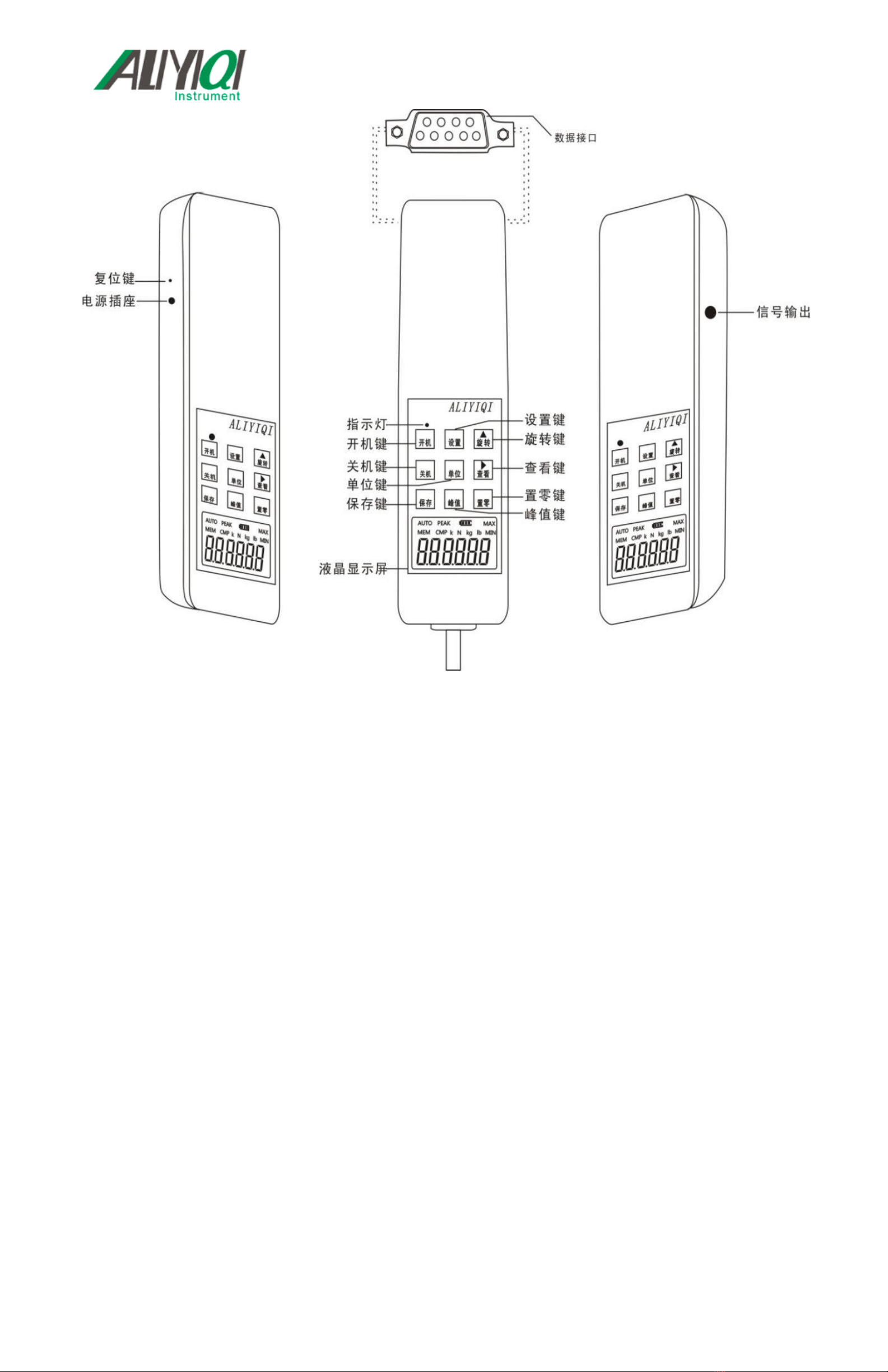
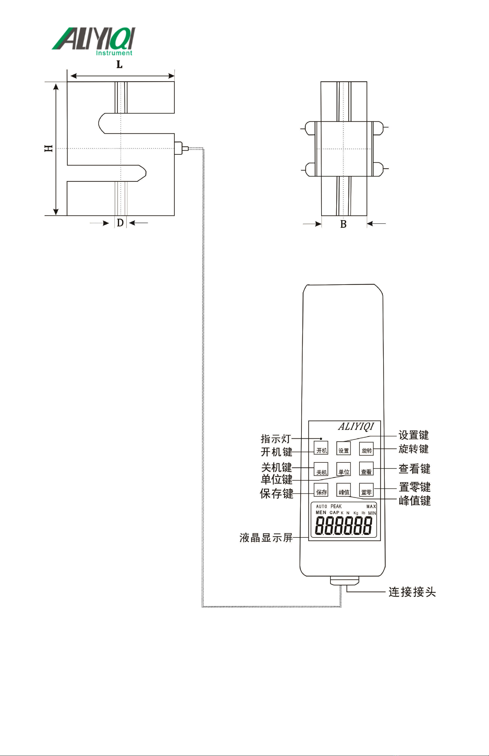
6. Key introduction
1. \"Boot \" key
When this button is pressed, the power is turned on and the model number is displayed. After booting, before
you press \"Clear \" to clear, the zero drift value of the analog signal may be displayed on the screen, just press
\"Clear \" to clear.
2. \"Shutdown \" key
In the power-on state, when you press this button, the power is turned off, but the stored data will not disappear.
When the power is turned on (that is, when the model is displayed and the measurement interface 0.00 is not
displayed), pressing the shutdown key at this time is unresponsive.
3. \"Save \" key
In the peak measurement interface state, press this key to save the test data displayed on the screen; in the
function setting interface state, press this key to save the set parameters. When the test data is stored in the
machine, \"MEM \" is displayed. This machine can store 447 data.
4. \"Settings \" key
For detailed settings, please refer to the description of various setting methods in \"Function Introduction \".
5. \"Unit \" key
Press this key to switch between measurement units, and three units of N (Newton), kg (Kilogram), and lb
(Pound) can be displayed cyclically. In the test data display state, the unit conversion of the same value can also
be completed. In the specifications above HF10K, it is composed of the letters \"K \" \"KN (kilo-newton) \", \"Kkg
(ton) \", \"Klb (kilo-pound) \".
6. \"Peak \" key
Each time you press this key, there will be a switch between \"PEAK \" display, \"AUTO PEAK \" display or
\"PEAK \" disappearing-that is, peak hold, peak hold automatic release, and real-time load value switching.
7. \"Rotate \" key
This key is only valid in the test interface. When you press this key, the measured value displayed on the screen
will rotate 180 degrees.
8. \"View \" key
When you press this key, the stored test data will be recalled and displayed on the screen. At this time, the
word\"\" MEM \"flashes-the number of saves is displayed first, and the saved data is automatically displayed
after 2 seconds. Press \"Zero \" to return to the measurement interface.
9. \"Zero \" key
When this key is pressed, the test value on the screen will be reset to zero. Note: When the instrument is
cleared, the instrument can only be cleared in the real-time measurement mode under peak and automatic peak.
※Choose a lighter fixture or remove the added load and clear it again.
※In the \"View \" interface, press and hold this button for 4 seconds, all the stored test data can be cleared
(may not be cleared in some states, then restart the machine after shutdown and then execute this function to
clear all saved data) .
Seven, boot display
Eight, function introduction
1. Setting function
a. Mode switching: After the boot is complete, press \"Settings \" key, \"TEST \" appears, press \"Settings\" key
again, 0001 mode appears, use \"Keys can choose different modes. As shown in the figure below:
0001 Standard test mode (factory default mode): In this mode, three states can be set, namely real-time load
state, peak hold state and automatic peak state. When there is no \"PEAK \" on the display, it is the real-time
value state of the load, and the test value changes with the change of the load; press \"Peak \" key, when the
word \"PEAK \" is displayed, it is the peak hold state The displayed test value is the MAX value of the test
(regardless of tension and pressure), which needs to be cleared manually; press \"Peak \" key again, \"AUTO
PEAK \" display, it is the automatic peak state, the displayed test The value is the MAX value in the test
(regardless of tension and pressure), and it will automatically disappear after returning to zero for 2 seconds,
and the next test can be performed.
0002 Push-pull peak mode: the function of simultaneously grasping the MAX load value in both directions of
pressure and tension. When testing the connector, grasp the function of the MAX load on both the positive and
negative sides of the insertion force and the extraction force.
0003 Peak thrust mode-only the MAX load function of insertion pressure is grabbed during the plug-in test
0004 Tension peak mode-when plugging and unplugging, only the function of MAX load that pulls out the
tension is captured.
0005 0006 Switch contact on-off force test mode-accurately measure the load value at the moment of contact on
and off action.
0005 The maximum force value of the external node from the moment of disconnection to the moment of
connection. Connect the two tested contacts to pins 4 and 5 of the data interface, press \"Peak \" to select the
peak mode, and apply pressure to the switch through the push-pull force gauge until the switch is turned on. The
measured force value at this time is the force value required to turn on the switch.
0006 The MAX value of the external node from on to off. Connect the two tested contacts to pins 4 and 5 of the
data interface (using the data plug in the accessory), press the\"\" peak\"key, select the peak mode, and apply
pressure to the switch through the push-pull force gauge until When the switch is open, the measured force
value at this time is the force value required to open the switch.
b. Various setting items
Press \"Settings \" key in the boot state, the display is \"TEST \", then press \" \"Key, you can view the setting
options. \" HIDT \", \" LODT \", \" STOP \", \" LOSET \", \" OFFT \", \" PE.SET \", \"GSET \", \"BACSET \",
\"RESET \". As shown below:
(HIDT) Test value upper limit setting: Set the test value upper limit, the upper limit default state is
99% of full scale. Above the upper limit is out of range, \"MAX \" is displayed. If you want to reset the upper limit,
use \" \"Key and \" \"Key setting. \" Save \"and return to the setting item interface. As shown below:
(LODT) Test value lower limit setting: Set the test value lower limit, the default value is 0 by default.
Below the lower limit is out of range, \"MIN \" is displayed. If you want to reset the lower limit, it is similar to the
previous operation, use \" \"Key and \" \"Key setting. \" Save \"and return to the setting item interface.
(STOP) The machine stop value setting, the default state is 99% of full scale. This product is used in
combination with our own motor table. When the test value exceeds the set machine stop value, the instrument
outputs a 5V signal and the machine receives the signal.
Operation method of this function:
a. Set the machine stop value for this instrument first: Setting method: Turn on, when the measurement interface
is displayed, press \"Settings\" to enter the machine stop value setting (display After (STOP), set its
value to the preset value.
b. There is a signal output jack on the right side of this instrument (see \"Outline Structure Diagram \" above).
Insert one end of the signal output line into this jack (socket) and the other end into the electric test bench
produced by our company The jack (socket) marked as signal input on the top (this signal output line is the
standard accessory of the electric test bench).
c. Starting the electric test bench produced by our company can realize the function that the motor stops
automatically when the test force exceeds the stop value of the machine.
(LOSET) Minimum saved value of peak value:MIN peak save value. In peak mode, when the
current value is less than this value, the peak value will not be saved.
(OFFT) Automatic shutdown time setting: under this setting item, use \" \"Key selection, you can set
10 minutes to 90 minutes to automatically shut down, you can also set \" 00 \"does not automatically shut down.
If you do not choose to shut down automatically, press \" Save \"after selection to complete the setting. That is
Return to the option interface. The default setting of the instrument is 10 minutes.
(PE.SET) Automatic peak save time: automatic peak save time, the unit is second, the default
value is 10, the setting cannot set this value to 0.
(G.SET)Gravity acceleration setting: The user can set the gravity acceleration value according to
the location of the region, the default value is 9.800.
(BACSET) Backlight function setting: under this setting item, use \" \"Key selection, if selected
\" (YES) \"means turn on the backlight function, choose \" (NO) \"means to turn off the backlight,
press \" Save \"to save and return to the setting item interface after selection.
(REF) Sensor reference value: manufacturer reference value, users do not need to pay attention.
(DIr) Positive and negative push-pull direction: used to switch the positive and negative direction of the
push-pull force gauge.
(SHIELD) Cancel the mask: Cancel the mask to display data below 1% of full scale. Press \"YES \"
to not cancel, press \"NO \" to cancel.
(RESET) Factory reset function:Under this setting item, press \"Settings \" to restore the factory
settings, and the machine will shut down. If you use the machine to restart the machine.
Nine, test
Press \"Power On \" key to turn on the power, and use the factory default settings as needed to directly test or
press the Set key to select the test mode and test.
1. Select the appropriate test joint fixture to be installed on the push-pull force gauge (for self-made fixtures,
please refer to the relevant data in \"Outline and Installation Dimensions \".
2. Please hold the push-pull force gauge firmly or install the push-pull force gauge on a suitable test machine for
testing. During the test, please make the tested force and the push-pull rod of the push-pull force gauge in line to
measure the accurate load .
3. After the test is completed, unload the load, turn off the power, remove the fixture, and clean the objects back
into the tool box for the next use.
10. Introduction to storing data and connecting to a computer
1. Store data
Press \"Save \" to save the data. The saved value is the value displayed on the current screen. \"MEM \" will
appear on the display. The stored data can also be saved after shutdown. When you use the\"\" View\"\" key to
view the saved data, \"MEM \" flashes, the number of saves appears first, and the saved value automatically
appears after 2 seconds. Press \"Clear \" key to exit save and enter test directly. Data can also be input into a
computer for analysis and processing. This machine can store 447 data. When there are more than 447 data,
the subsequent data will not be saved.
2. Data clearing
When viewing the interface, press the\"zero\" key for more than four seconds, all the saved data will be cleared,
and the word\"MEM\" will disappear.
3. Introduction to connecting to a computer
a. Use the\"Data Export Program\" in the CD-ROM to export the data saved in the instrument to the computer.
View, print, test times, average value, MAX value, MIN value and judge whether the test result meets the set
requirements. (For details, please refer to the description in\"Data Export Program\")
b. Use the\"Synchronization Test\" in the CD to realize the curve of force value and time. (For details, please
refer to the description in\"Synchronization Test\")
4. If connecting with PLC, modbus protocol needs to be customized.
11. Safety Precautions
1. Matters needing attention:
a. If you purchase this instrument, you need to charge it for 4 ~ 6 hours before it can be used normally.
b. To purchase this instrument, you must use the RS232 computer cable included in the company's distribution
accessories.
c. If the operation is wrong, it may damage the instrument or cause serious accidents. This manual points out
important matters for preventing accidents and how to use the instrument. Please read this manual carefully
before use, and keep it properly after reading to prepare for reading here.
d. If you are testing the impact load, please select the model whose MAX load is twice the impact load to be
tested.
2. Warning matters:
a. During destructive testing, protective masks and gloves should be worn to prevent the splashed material from
hurting the human body during the testing process.
b. Do not use damaged or severely bent fixtures. For self-made fixtures, please refer to the relevant parameters
in this manual (the company also provides various fixtures, customers can choose according to need; purchase
separately).
C. Do not use the instrument beyond the MAX range. Otherwise, the sensor may be damaged or even an
accident may occur.
d. When the test value exceeds 100% of full scale, the buzzer will continue to sound. In this case, please quickly
release the added load or reduce the load. When the test value exceeds 120% of full scale, the instrument may
be damaged.
3. Solve the crash status: When the instrument crashes unexpectedly, use a small round rod with a hard object
to press the\"Reset\" button on the left side of the instrument to quickly reset and shut down.
4. Safety matters:
a. Please use the matching charger to charge, otherwise it will cause circuit failure and even fire.
b. Do not use a power supply other than the rated voltage of the charger, otherwise it may cause electric shock
or fire.
c. Do not pull out or insert the power supply with wet hands, otherwise it may cause electric shock.
d. Do not pull the power cord of the charger to pull out the plug, so as to avoid the electric cord being broken and
being subjected to electric shock.
e. Please clean the machine with a soft cloth. Immerse the cloth in water soaked with detergent and wring it out
to remove dust and dirt. Note: Do not use volatile chemicals to clean the machine (such as volatile agent,
thinner, alcohol, etc.).
f. Do not operate the machine in the following environment
①Humid environment
②Dusty environment
③Where oil or chemicals are used
④Places with earthquake sources around
g. Please use and store within the specified temperature and humidity range, otherwise it may cause malfunction
of the instrument.
h. Do not dismantle, repair or modify the machine by yourself, these actions may cause the instrument to
malfunction.
i. Other matters that need to be paid attention to in safety production.
J, HF series push-pull force meter confirmation items before repair
12. Data interface (9PIN)
Thirteen, outline and installation dimensions
14. List of random attachments
charger
Compression
fixture
Stretching
fixture
Extension
rod
Mounting
screws
Instructions
Inspection
certificate
Certificate of
conformity
HF-2
1
4
1
1
4
1
1
1
HF-3
1
4
1
1
4
1
1
1
HF-5
1
4
1
1
4
1
1
1
HF-10
1
4
1
1
4
1
1
1
HF-20
1
4
1
1
4
1
1
1
HF-30
1
4
1
1
4
1
1
1
HF-50
1
4
1
1
4
1
1
1
HF-100
1
4
1
1
4
1
1
1
HF-200
1
4
1
1
4
1
1
1
HF-300
1
4
1
1
4
1
1
1
HF-500
1
4
1
1
4
1
1
1
HF-1000 (built-
in)
1
4
1
1
4
1
1
1
HF-1000
(external)
1
3
2
-
4
1
1
1
HF-2000
1
3
2
-
4
1
1
1
HF-3000
1
3
2
-
4
1
1
1
HF-5000
1
3
2
-
4
1
1
1
HF-10K
1
3
2
-
4
1
1
1
HF-20K
1
3
2
-
4
1
1
1
HF-30K
1
3
2
-
4
1
1
1
HF-50K
1
3
2
-
4
1
1
1
HF-100K
1
3
2
-
4
1
1
1
HF-200K
1
3
2
-
4
1
1
1
HF-300K
1
-
-
-
4
1
1
1
HF-500K
1
-
-
-
4
1
1
1
HF-1000K
1
-
-
-
4
1
1
1
HF-2000K
1
-
-
-
4
1
1
1
Feedback

This manual suits for next models

10

Other Aliyiqi Test Equipment manuals

Aliyiqi ADT Series User manual

Aliyiqi

Aliyiqi ADT Series User manual

Aliyiqi ANS-0.5 User manual

Aliyiqi

Aliyiqi ANS-0.5 User manual

Popular Test Equipment manuals by other brands

AlcoMate premium AL-7000 Operator's manual

AlcoMate

AlcoMate premium AL-7000 Operator's manual

Lovibond MD 100 instruction manual

Lovibond

Lovibond MD 100 instruction manual

Monacor IMG Stageline STROBE-185 quick guide

Monacor

Monacor IMG Stageline STROBE-185 quick guide

CraftyMech TPG manual

CraftyMech

CraftyMech TPG manual

GRAS 50GI-R instruction manual

GRAS

GRAS 50GI-R instruction manual

Hameg HM1507-3 Service manual

Hameg

Hameg HM1507-3 Service manual

Fluke DTX Series Technical reference handbook

Fluke

Fluke DTX Series Technical reference handbook

impact CN842 user guide

impact

impact CN842 user guide

LR-Cal LLC 100 operating manual

LR-Cal

LR-Cal LLC 100 operating manual

VOLTCRAFT DSO-4062A operating instructions

VOLTCRAFT

VOLTCRAFT DSO-4062A operating instructions

ULTIMATE SPEED KH 4103 manual

ULTIMATE SPEED

ULTIMATE SPEED KH 4103 manual

Instron 68TM-10 Preinstallation manual

Instron

Instron 68TM-10 Preinstallation manual

Keysight Technologies InfiniVision 6000L Series user guide

Keysight Technologies

Keysight Technologies InfiniVision 6000L Series user guide

tibelec 0900001 instructions

tibelec

tibelec 0900001 instructions

Gamry Interface 5000 Operator's manual

Gamry

Gamry Interface 5000 Operator's manual

PDK PCS-P100 user manual

PDK

PDK PCS-P100 user manual

ZKETECH EBC-A10H user manual

ZKETECH

ZKETECH EBC-A10H user manual

Waekon PWM Power Pro 78065 user guide

Waekon

Waekon PWM Power Pro 78065 user guide

manuals.online logo
manuals.online logoBrands
  • About & Mission
  • Contact us
  • Privacy Policy
  • Terms and Conditions

Copyright 2025 Manuals.Online. All Rights Reserved.