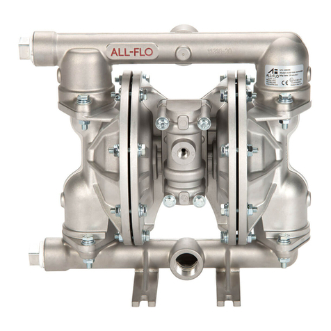
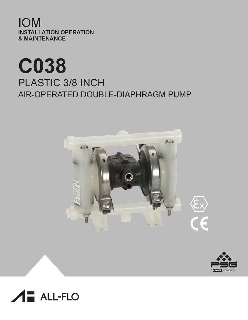
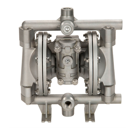
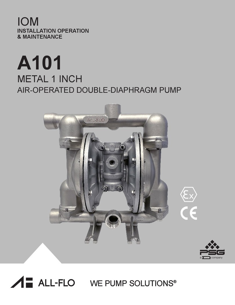
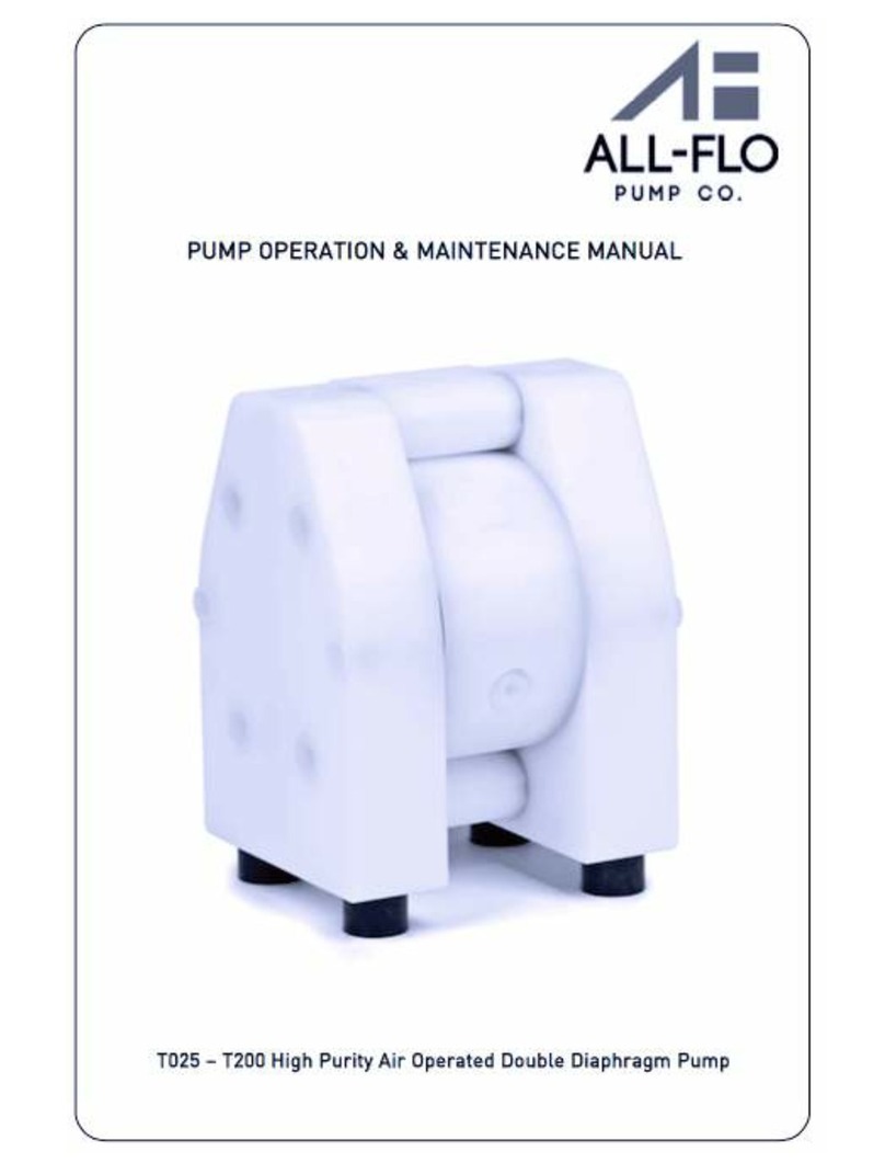
All-Flo P300 Manual

A-
ALL-F
PUMP OPERATION & MAINTENANCE MANUAL
(
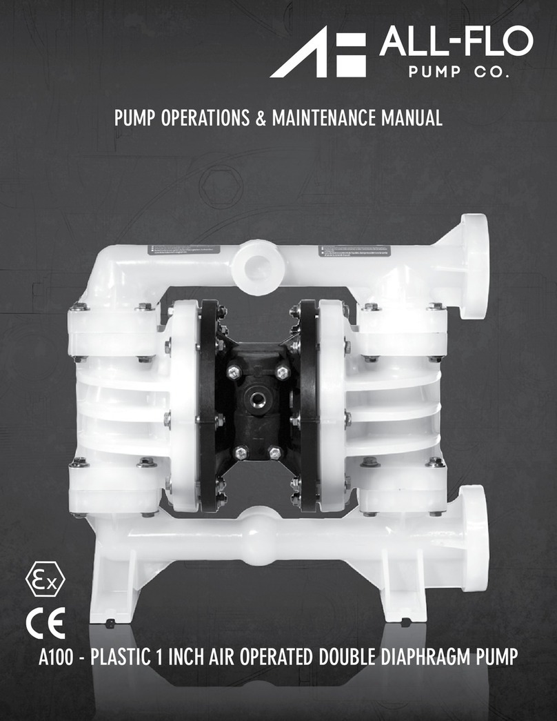
P300 High Density Polyethylene Air Diaphragm Pump

2 I All-Flo Pump Co.
1. Warnings and Caution _______________________________________________________________________ 3
2. Pump Model Matrix __________________________________________________________________________4
3. Pump Dimensions ___________________________________________________________________________5
4. Pump Integrated with Pulsation Dampener Dimensions ______________________________________________6
5. Pump Specifications and Performance Curve ______________________________________________________7
6. Installation, Troubleshooting and Maintenance _____________________________________________________8-12
Installation ______________________________________________________________________________ 8-9
Troubleshooting __________________________________________________________________________10
Operation _______________________________________________________________________________11
Maintenance _____________________________________________________________________________12
7. Torque Specifications _________________________________________________________________________13
8. Exploded View and Parts List ___________________________________________________________________14-15
9. High Pressure System (Option Code HP) __________________________________________________________16
10. High Pressure System Appearance and Dimensions _________________________________________________ 17
11. High Pressure System Exploded Views ___________________________________________________________ 18
12. High Pressure System Performance Curves ________________________________________________________19
13. Warranty and Registration ______________________________________________________________________20

3I All-Flo Pump Co.

4 I All-Flo Pump Co.
Model Designation Matrix
PRODUCT SERIES
FLUID CONNECTI
INTERM
NER CHAMIN
ON TYPE
O-RINGS
VAL
L
VE SEAT
VALVE/BAL
DIAPHRAGM
SPE
W
CIAL (
ARE,
O
THER)
FLUID C
EDI
BER
TE/
S/
A
HAMBER
MANIFOLDS
SPECIAL (HA
OR
SPE
TING
CIAL
RD
MUFFLER)
(P )
PX X X -1 2 3- 4 5 6 7
-8 910
PUMP SIZE
2
3
5
1
4
INTERMEDIATE / INNER CHAMBER
H = High Density Polyethylene
J = Conductive Polyethylene
FLUID CHAMBER / MANIFOLDS
H = High Density Polyethylene
J = Conductive Polyethylene
DIAPHRAGMS
E = EPDM
P = Integral PTFE
VALVE/BALL
E = EPDM
T = PTFE
3 = Stainless Steel
6
7
VALVE SEAT
H = High Density Polyethylene
O-RINGS
E = EPDM
T = PTFE
SPECIAL OPTION
G70 = Standard
Z001 = Pump Integrated with Pulsation
Dampener
PUMP SIZE
300 = 3 Inch
FLUID CONNECTION TYPE
N = FNPT
B = FBSPT
A = ANSI Flange
D = DIN Flange
0
WET END REPAIR KIT
Wet end kits are available and
consist of diaphragms, (back-up
diaphragms if required), balls,
seats and seat O-Rings.
See matrix below.
Bold indicates recommended options
P W E 003 4 5 6 7
-
-
-
AIR END REPAIR KIT
Air end repair kit contains pilot sleeve
assembly and main air valve.
MATERIAL
SERIE
ODPR
EP
S
UCT
PUMP SIZE
AIR END
AIRR KIT
-RINGS
VAL
BALL
O
VE SEAT
AL
A
VE/
DIAPHR
V
GM
PRODUCT
SERIES
WET END
REPAIR KITS
PUMP SIZE
MATERIAL
P A K 0
- 3 0-
0
-
3 0
- PP

Pump Dimensions
A B C D F H I J K L
P300 18.90" 22.83" 31.50" 3.94" 15.28" 27.17" 1.57" 2.95" 15.55" 19.49"
(480 mm) (580 mm) (800 mm) (100 mm) (388 mm) (690 mm) (40 mm) (75 mm) (395 mm) (495 mm)
5 I All-Flo Pump Co.

Pump Integrated with Pulsation Dampener Dimensions
P300
A18.90”(480 mm)
B22.83”(580 mm)
C31.50”(800 mm)
D3.94”(100 mm)
E 15.28”(388 mm)
F3”
G27.17”(690 mm)
H3/4”
I1.57”(40 mm)
ØJ 2.95”(75 mm)
K15.55”(395 mm)
L19.49”(495 mm)
M6.30”(160 mm)
N5/8”
O10.28”(261 mm)
P1/2”
Q14.17”(360 mm)
6 I All-Flo Pump Co.

Pump Specifications
P300
Dimension
Air Inlet 3/4”
Liquid Inlet 3”
Liquid Outlet 3”
375 lbs
(170 kg)
Performance
211 gpm
(800 lpm)
Max pressure 120 PSI (8.2 bar)
9/16”
(12 mm)
16.4 ft-H2O
(5 m-H2O)
Suction lift wet
29.5 ft-H2O (9.0 m-H2O)
Temperature limits
158 °F (70°C)
Max Solids
Suction lift dry
Weight
Max capacity
Performance Curves
7 I All-Flo Pump Co.

8 I All-Flo Pump Co.

flexible connection
flexible
connection
vacuum
gauge
shut-off
valve
shut-off
valve
pressure
gauge
SUCTION
DISCHARGE
air shut-off
valve
combined air
filter and
regulator
needle
valve
AIR SUPPLY
9 I All-Flo Pump Co.

10 I All-Flo Pump Co.

1) Start the air compressor.
2) Open the air valve. Using a regulator to adjust the supply air pressure within the permissible range.
3) Open the flow valve on the discharge side.
4) First, check that fluid is flowing inside the piping and is being pumped to the discharge side, and then fully open the air valve.
Adjust the flow valve on the discharge side, or adjust the supply air pressure.
!
CAUTION
!
CAUTION
Before starting the pump, check that all piping is properly connected.
Before starting the pump, check that all the bolts are securely tightened.
Check that the regulator and the drain valve on the discharge side are closed and that the valve on
the suction side is opened if applicable.
The supply air pressure may initially rise during closing the flow valve. Make sure that the pressure is kept
within the normal operating range.
The permissible suction flow speed can vary depending upon the viscosity and specific gravity of the fluid,
the suction stroke and other factors. However in case of a rapid growth of the pump speed (flow speed of
fluid), cavitations will occur. This will reduce pump performance and may cause a malfunction. In order to
prevent cavitations, adjust the supply air pressure and the flow.
If fluid is not discharged after you start the pump, or if you hear an abnormal noise or notice any
irregularity, shut down the pump immediately.
11 I All-Flo Pump Co.

1) Remove the hose from the suction side of the pump.
2) Close the flow valve on the discharge side and open the drain valve. Then start air pressure for a
while to discharge possibly much fluid remaining inside the pump.
3) Remove the hose from the discharge side, and attach different hoses to the suction side and the
discharge side for cleaning.
4) Be ready with a vessel with cleaning solution, the kind appropriate for the type of fluid pumped. Next
connect the suction-side and the discharge-side hoses of the pump.
5) Start the pump air pressure slowly, and let the cleaning solution circulate for sufficient cleaning.
6) Flush with clean water.
7) Remove the hose from the suction side of the pump, run the pump for a while to purge the pump of
remaining fluid as much as possible.
!
CAUTION
!
WARNING
Make sure that compressed air is not supplied to the pump BEFORE you start cleaning the pump.
Make sure that the pump is not pressurized BEFORE you start cleaning the pump.
Be extremely careful when removing piping - the fluid will run/flow out.
After cleaning with clean water, turn the pump upside-down to let the water flow out.
12 I All-Flo Pump Co.

Close the air valve of the pump and shut off the supply air.
Before starting pump operation, conduct the following check procedures every day. In case there appears any
irregularity, do NOT start running the pump until the cause of the irregularity has been determined and
corrective measures have been taken.
a)Make sure that there is no leakage of fluid from any connection part or the pump.
b)Make sure that there are no cracks in the pump casing or piping.
c) Check the tightness of every bolt of the pump.
d)Make sure that the connection parts of the piping and peripheral equipment are not loose.
e)Make sure that any parts of the pump that are to be replaced at regular intervals have been changed.
Pump Size
P300 212in-lbs. (24 N-m)
Maximum Torque Specifications
Torque Values for Housing Bolts
!
CAUTION
!
CAUTION
The pump can be shut down with the flow valve closed while air is being supplied. However DO NOT leave
the pump in this condition for many hours without supervision - there is a risk of a leak from the pump or
piping, and fluid may continue flowing out of the position of leakage.
When the pump is shut down while pumping slurry, particulate matter contained in the slurry will be
deposited and get stuck inside the out chamber. Therefore after finishing work the pump must be cleared of
the remaining fluid. Otherwise when starting the pump again, the diaphragm may get damaged and the
center rod may bend.
Keep a vessel below the relief valve for any drain off.
Be careful! - Fluid under pressure will gush out the moment you open the valve.
If the pump is unused for a prolonged period, purge and clean it.
13 I All-Flo Pump Co.

1
2
3
4
7
7
9
11
12
13
15
14
17
22
24
25
26
27
28
16
30
3
5
18
70
82
83
97
98
14 I All-Flo Pump Co.

P300
1 2 Pump housing PE HP-2 80 01 20
PE conductive HP-2 80 01 21
2 1 Center housing PE HP-1 80 10 20
PE conductive HP-1 80 10 21
3
1 Suction port PE HP-2 80 25 20
PE conductive HP-2 80 25 21
1 Discharge port PE HP-2 80 025 20
PE conductive HP-2 80 025 21
4 2 Diaphragm TFM/PTFE HP-1 80 50 05
EPDM HP-1 80 50 08
NBR HP-1 80 50 10
5 4 Valve balls PTFE HP-1 80 60 23
EPDM HP-1 80 60 08
NBR HP-1 80 60 10
7 4 Sealing inlet/outlet -
SET
EPDM/EPDM HP-2 80 70 08
PTFE/FPM HP-2 80 73 14
PTFE/EPDM HP-2 80 73 15
PTFE-c./FPM HP-2 80 73 16
PTFE-c./EPDM HP-2 80 73 17
9 8 Housing bolt AISI 304 HP-2 80 042 50
11 4 Shock absorber NR/St37 HP-1 80 69 06
12 16 Nut with washer, cpl. AISI 304 HP-2 80 045 50
13 1 Air valve PET/NBR HP-1 80 020 31
PET/FPM HP-1 80 020 32
14 1 Shaft AISI 304 HP-1 80 40 50
15 6 O-ring NBR HP-1 40 87 10
FPM HP-1 40 87 09
16 2 Center housing seal PE HP-1 80 85 22
17 1 Muffler Diverse HP-1 80 99 00
18 1 Air adapter PP HP-1 80 46 28
22 4 Valve seat PE HP-2 80 54 20
PE-conductive HP-2 80 54 21
24 2 Plug lower PE HP-2 80 59 20
PE-conductive HP-2 80 59 21
25 2 Plug upper PE HP-2 80 55 20
PE conductive HP-2 80 55 21
26 2 Valve stopper PE HP-2 80 39 20
PE conductive HP-2 80 39 21
27 4 Bolt PE HP-2 80 38 20
PE conductive HP-2 80 38 21
28 2 Plug upper sealing FEP/FPM HP-2 80 78 04
EPDM HP-2 80 78 08
NBR HP-2 80 78 10
30 2 O-ring for center
housing seal NBR HP-1 80 85 10
35 1 Center housing
complete PE HP-1 80 11 20
PE conductive HP-1 80 11 21
70 16 Pump housing plug PE HP-2 80 058 20
82 2 Shaft allen pin screw AISI 304 HP-1 80 540 50
83 1 Muffler adapter PE HP-1 80 299 20
97 1 Valve seat key AISI 304 HP-1 80 254 50
98 1 Upper/lower plugs
key (SK5) diverse HP-1 80 158 00
99 1 Air valve (SK4) diverse HP-1 08 58 00
15 I All-Flo Pump Co.

16.7 High Pressure System (option code HP)
All-Flo diaphragm pumps can be fitted with High Pressure option. It is a very compact unit that can be
mounted directly to the filter press. It has been designed for charging filter presses with chemical wastes and special
sludge. An extern pressure booster doubles or quadruples the delivery pressure.
Filter presses with All-Flo P300 pump
Automatic adaptation
When slurry is transferred to achamber filter press, first the chambers get filled while the pressure tends to zero.
Under the increasing filling-level the solids assemble at the filter cloths. This requires a pressure that continuously rises
with the increasing content of solids. Under a constant flow quantity the pressure would rise extremely fast.
The drive of the HP pump by compressed air causes adiminution of the flow quantity according to the increasing
counter-pressure in the filter press. This produces asoft filtration curve, automatically self-regulating according to the
filling level of the filter press. This is independent from the properties of the slurry. No pressure tank nor pressure
transmitter nor speed control are required. The complete HP pump works without electric energy.
End of filtration process
When the filter press is filled with the solids so far that no more slurry can be taken up, the pressing period is
terminated. The air operation of the All-Flo pumps then reduces the flow rate to zero while the outlet pressure holds
the required level compressing the filter cake. Excellent results in drying are obtained. At the end of the pressing period
the pump simply stops.
Pressure adjustment
The required pressure in the filter press is comfortably adjusted by the height of the air pressure supplying the
charging station. For arequired pressure of 12 bar the HP pump has to be supplied with 6bar when the pump with a
pressure transmission of 1:2 is applied. In the case that higher pressures are necessary or there is only alower air
pressure available, the HP pump with 1:4 transmission is applied.
Low air consumption
The charging stations needs the maximum air quantity only during the filling period. The more the press is filled, the
more slowly the pump works. So the air consumption slowly reaches zero during progressing filtration.
16 I All-Flo Pump Co.

Appearance and dimensions of high pressure system (pump with HP option)
A B C D E F G H I ØJ K L M N O P
DM 15/55 6.02 in
(153 mm) 7.15 in.
(182 mm) 14.64 in.
(372 mm) .98 in.
(25 mm) 1/2" 3.42 in.
(87 mm)1/4" 8.54 in.
(217 mm) .708 in.
(18 mm) 1.18 in.
(30 mm) 4.40 in.
(112 mm) 5.35 in.
(136 mm) 7.67 in.
(195 mm) 12.63 in.
(321 mm) 9.96 in.
(253 mm) 13.11 in.
(333 mm)
DM 25/125 7.87 in.
(200 mm) 9.37 in.
(238 mm) - 1.37 in.
(35 mm) 1" 4.84 in.
(123 mm) 1/4" 11.29 in.
(287 mm) 1.102 in.
(28 mm) 1.57 in.
(40 mm) 5.51 in.
(140 mm) 6.69 in.
(170 mm) 11.45 in.
(291 mm) 16.61 in.
(422 mm) 13.74 in.
(349 mm) 18.18 in.
(462 mm)
DM 40/315 10.62 in.
(270 mm) 12.51 in.
(318 mm) - 1.65 in.
(42 mm) 1-1/2" 4.29 in.
(109 mm) 1/2" 15.27 in.
(388 mm) 1.18 in.
(30 mm) 2.36 in.
(60 mm) 7.48 in.
(190 mm) 8.93 in.
(227 mm) 11.45 in.
(291 mm) 20.82 in.
(529 mm) 19.68 in.
(500 mm) 23.62 in.
(600 mm)
DM 50/565 13.77 in.
(350 mm) 15.47 in.
(393 mm) - 1.77 in.
(45 mm) 2" 6.22 in.
(158 mm) 1/2" 19.09 in.
(485 mm) 1.18 in.
(30 mm) 10.62 in.
(270 mm) 11.10 in.
(282 mm) 15.90 in.
(404 mm) 24.17 in.
(614 mm) 22.04 in.
(560 mm) 27.16 in.
(690 mm)
75 76
77
78
79
80
81
74
17 I All-Flo Pump Co.
2.36 in.
(60 mm)

High pressure system (pump with HP option) –exploded view
Spare part list, high pressure system
Pump size DM 15/55 DM 25/125 DM 40/315 DM 50/565
Code Item Pc Description Material Part no. Part no. Part no. Part no.
HPS
HPM
74 2 Pump housing for HP option PE HP-2 15 601 20 HP-2 25 601 20 HP-2 40 601 20 HP-2 50 601 20
PTFE HP-2 15 601 23 HP-2 25 601 23 HP-2 40 601 23 HP-2 50 601 23
PE conductive HP-2 15 601 21 HP-2 25 601 21 HP-2 40 601 21 HP-2 50 601 21
PTFE conductive HP-2 15 601 24 HP-2 25 601 24 HP- 40 601 24 HP-2 50 601 24
75 1 Distance plate short AISI 304 HP-2 15 164 50 HP-2 25 164 50 HP- 2 40 164 50 HP-2 50 164 50
76 1 Distance plate long AISI 304 HP-2 15 264 50 HP-2 25 264 50 HP-2 40 264 50 HP-2 50 264 50
77 1/2* Air pressure booster SMC Diverse HP-9 15 64 00 HP-9 15 64 00 HP-9 40 64 00 HP-9 50 64 00
Air pressure booster
MetalWork Diverse HP-9 15 964 00 HP-9 15 964 00 HP-9 40 964 00 HP-9 50 964 00
78 1 Mounting set for booster
SMC (HPS) AISI 304 HP-9 15 S42 50 HP-9 15 S42 50 HP-9 40 S42 50 HP- 9 50 S42 50
Mounting set for booster
MetalWork (HPM AISI 304 HP-9 15 M42 50 HP-9 15 M42 50 HP-9 40 M42 50 HP-9 50 M42 50
79 6 / 8* Housing bolt AISI 304 HP-2 15 142 50 HP-2 25 142 50 HP- 2 40 142 50* HP-2 50 142 50*
80 2 Distance plate bolt, cpl. AISI 304 HP-2 15 942 50 HP-2 25 942 50 HP-2 40 942 50 HP-2 50 942 50
82 Upper plug for HP option PE HP-2 15 655 20 HP-2 25 655 20 HP-2 40 655 20 HP-2 50 655 20
PTFE HP-2 15 655 23 HP-2 25 655 23 HP-2 40 655 23 HP-2 50 655 23
PE conductive HP-2 15 655 21 HP-2 25 655 21 HP-2 40 655 21 HP-2 50 655 21
PTFE conductive HP-2 15 655 24 HP- 25 655 24 HP-2 40 655 24 HP-2 50 655 24
83 2/4** Upper plug O-ring external NBR HP-2 15 278 10 HP-2 25 278 10 HP- 40 278 10** HP-50 278 10
EPDM HP-2 15 278 08 HP-2 25 278 08 HP-2 40 278 08** HP-50 278 08
84 2 Plate for upper plug AISI 304 HP-1 15 464 50 HP-1 25 464 50 HP-1 40 464 50 HP-1 50 464 50
85 8 Upper plug plate screw AISI 304 HP-1 15 564 50 HP- 25 564 50 HP-1 40 564 50 HP-1 50 564 50
78
85
84
83
82 81
80
75
77
76
74
79
High pressure system (pump with HP option) –exploded view
Spare part list, high pressure system
18I All-Flo Pump Co.
Performance curves
19 I All-Flo Pump Co.

Warranty
20 I All-Flo Pump Co.
Table of contents
Other All-Flo Water Pump manuals
Popular Water Pump manuals by other brands

Becker
Becker DT 4.16 operating instructions

CountyLine
CountyLine CL30210 owner's manual

caprari
caprari D-M Series Use and maintenance instructions

KSB
KSB Etanorm FXV Installation & operating manual

Wanner Engineering
Wanner Engineering STAN-COR MK Series Installation and operation manual

Crane
Crane BARNES STEP-SS Series Installation and operation manual

Ebinger
Ebinger TBW 36 Instruction booklet

Gespasa
Gespasa IRON-50 instruction manual

AquaScape
AquaScape Ultra 400 Instructions & maintenance

Ingersoll-Rand
Ingersoll-Rand 66615X-X-C Operator's manual

APT
APT AWP 2 Safety & Operating Instructions

Crane
Crane PROSSER STANDARD-LINE 9-81000 Series Installation and operation manual