All Weather Inc 8339 User manual

All Weather Inc. • 1065 National Drive • Sacramento, CA 95834 • USA • 800.824.5873 • www.allweatherinc.com
Model8339
CloudHeightIndicatorLaserCeilometer
User’s
Manual
Rev. M

Copyright ©2013–2021, All Weather, Inc.
All Rights Reserved. The information contained herein is proprietary and is provided solely for the purpose of
allowing customers to operate and/or service All Weather, Inc. manufactured equipment and is not to be released,
reproduced, or used for any other purpose without written permission of All Weather, Inc.
Throughout this manual, trademarked names might be used. Rather than put a trademark (™) symbol in every
occurrence of a trademarked name, we state herein that we are using the names only in an editorial fashion and to
the benefit of the trademark owner, and with no intention of infringement. All Weather, Inc. and the All Weather,
Inc. logo are trademarks of All Weather, Inc.
Disclaimer
The information and specifications described in this manual are subject to change without notice.
Latest Manual Version
For the latest version of this manual, see the User Manuals page under Support on our Web site at
www.allweatherinc.com/.
All Weather, Inc.
1065 National Drive, Suite 1
Sacramento, CA 95834
Tel.: (916) 928-1000
Fax: (916) 928-1165
Contact Customer Service
Phone support is available from 8:00am - 4:30pm PT, Monday through Friday. Call 916-928-1000 and ask for
“Service.”
Online support is available by filling out a request at www.allweatherinc.com/customer/support.html
E-mail your support request to support@allweatherinc.com

Model 8339 Ceilometer User’s Manual
Revision History
Revision
Date
Summary of Changes
G
2011 Aug 23
Added RS-485 communication, polling commands with CRC, reboot and laser
temperature control warning status bits.
H
2011 Oct 1
Corrected 8329 mode baud rate
J
2011 Oct 4
Enhanced description of grounding requirements during installation.
K
2014 Nov 20
Added cross-reference to status codes in Section 2.3.2 and simplified lens cleaning to
clean water
L
2016 May 26
Updated 8339-F-019/8339-G-019 wiring diagrams to add wire colors
M
2021 Feb 5
Added RS-485 surge suppression

Model 8339 Ceilometer User’s Manual
TABLEOFCONTENTS
1. OVERVIEW.........................................................................................................................1
1.1 Models ........................................................................................................................................1
1.2 Accessories.................................................................................................................................2
2. THEORY OF OPERATION .................................................................................................3
2.1 General Description....................................................................................................................3
2.2 Theory of Operation ...................................................................................................................3
2.2.1 Functional Description........................................................................................................4
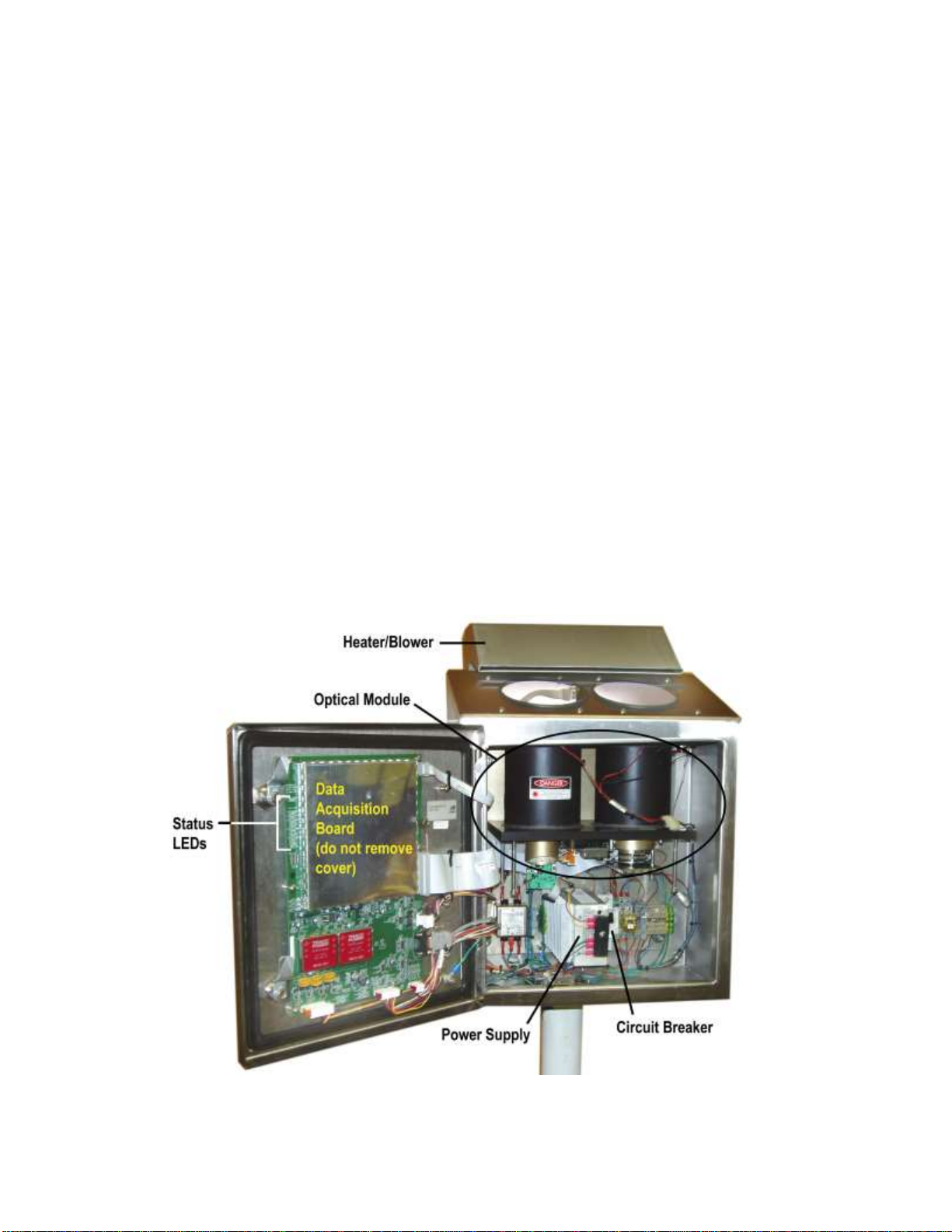
2.3 Modules ......................................................................................................................................5
2.3.1 Optical Module ...................................................................................................................5
2.3.2 Data Acquisition Board.......................................................................................................8
2.4 Fault Detection..........................................................................................................................10
3. DATA COMMUNICATION.................................................................................................11
3.1 8339 Native Format..................................................................................................................11
3.1.1 Communication Parameters..............................................................................................11
3.1.2 Data Format ......................................................................................................................11
3.1.3 Poll Commands.................................................................................................................12
3.2 8339 Sky Condition Format......................................................................................................14
3.2.1 Data Format ......................................................................................................................15
3.3 8329 Format..............................................................................................................................16
3.3.1 Communication Parameters..............................................................................................16
3.3.2 Data Format ......................................................................................................................16
3.4 8339 ASOS ICD.......................................................................................................................17
3.4.1 Communication Parameters..............................................................................................17
3.4.2 8339 ASOS ICD Command Set........................................................................................17
4. UNPACKING AND INSTALLATION..................................................................................27
4.1 Unpacking.................................................................................................................................27
4.2 Installation ................................................................................................................................27
4.2.1 Mechanical Mounting.......................................................................................................28
4.2.2 Optional Heater/Blower....................................................................................................29
4.2.3 Ceilometer Lightning Surge Suppressor...........................................................................30
4.2.4 Ceilometer Data Connection.............................................................................................31
4.2.5 Ceilometer Power Connection..........................................................................................32
4.2.6 Final Steps.........................................................................................................................32
5. OPERATION.....................................................................................................................34
5.1 Power Up..................................................................................................................................34
5.2 Checkout...................................................................................................................................34
6. MAINTENANCE ................................................................................................................35
6.1 Periodic Maintenance ...............................................................................................................35
6.1.1 Window Cleaning —Monthly or as required...................................................................35

Model 8339 Ceilometer User’s Manual
6.1.2 Blower Check —Monthly................................................................................................35
6.1.3 Desiccant Replacement —Triannually............................................................................35
6.1.4 Blower Housing Cleaning —Annually............................................................................36
6.2 Fuse Replacement.....................................................................................................................36
7. TROUBLESHOOTING ......................................................................................................37
7.1 Using the Status Message.........................................................................................................37
8. REMOVAL AND REPLACEMENT ....................................................................................40
8.1 Removing Modules...................................................................................................................40
8.1.1 Data Acquisition Board.....................................................................................................41
8.1.2 Optical Module .................................................................................................................42
8.1.3 DIN Rail Components.......................................................................................................43
8.2 Replacing Modules...................................................................................................................44
8.2.1 Data Acquisition Board (Figure 18) .................................................................................44
8.2.2 Optical Module (Figure 19)..............................................................................................44
8.2.3 DIN Rail Components.......................................................................................................45
9. FIRMWARE UPDATES.....................................................................................................46
10. SPECIFICATIONS ..........................................................................................................47
11. WARRANTY....................................................................................................................49
12. DRAWINGS ....................................................................................................................50

Model 8339 Ceilometer User’s Manual
WARNINGS
Eye Safety
The 8339 Cloud Height Indicator (Ceilometer) uses an invisible IR laser
configured as Class I according to FDA regulation CFR Title 21, Section
1040.10. This standard is system-specific, meaning that it is possible to
reconfigure the system into a dangerous mode. In order to ensure continued
eye safety over the life of the product:
a) Never use external condensing optics devices, such as binoculars,
lenses, etc., to look into the output aperture. Also avoid reflections
from mirrors with condensing properties, i.e., mirrors with concave
curvatures. The Ceilometer is safe only as long as the beam remains
unmodified from its output form. Though the system is also safe
with the door opened, an interlock switch prevents the laser from
being fired without the door closed.
b) Never make modifications or adjustments to the Optical Module.
Fuses
Use only replacement fuses specified in the maintenance section of this
manual. In addition to observing the current rating, use only “slo blo” fuses.
Failure to do so may damage the system. If fuses blow repeatedly, a serious
condition is indicated.
Equatorial
Filter
An equatorial filter that prevents damage to the laser from exposure to
direct sunlight is installed on every 8339 Ceilometer. This filter causes no
degradation in performance.

Model 8339 Ceilometer User’s Manual
1
1. OVERVIEW
The Model 8339 Laser Ceilometer measures the height and thickness of up to four cloud layers
simultaneously to a distance of 25,000 vertical feet. It can also report vertical visibility.
Its precision makes it ideal for applications requiring the highest performance and reliability, such as
aviation and meteorological studies.
A laser pulse is emitted towards the zenith above the Ceilometer, and the backscatter is analyzed. The
laser pulse moves at speed of light, and the difference between the emission of the pulse and the return
of the backscattered signal is used to calculate the altitude of each cloud base and top.
Some cloud types have poorly defined borders or a sparse composition, and are much more difficult to
measure than others. Depending on the current and historical sky conditions, an adaptive algorithm
determines the frequency at which the pulses should be emitted to maintain accuracy.
Weather conditions such as heavy precipitation and low clouds can lead to reporting errors in other
Ceilometer designs. Proprietary algorithms and digital techniques developed by All Weather Inc.
based on 20 years of cloud detection research and manufacturing experience are are used by the
Model 8339 Ceilometer to provide accurate information even in difficult circumstances.
Sensing circuits and optimization algorithms control the pulse frequency, output power, and
temperature of the laser itself in order to extend its life dramatically.
The 8339 is enclosed in a NEMA 4X electro-polished 304 stainless steel package that will stand up to
the harshest environmental conditions from corrosive marine air to blowing desert sand. The 8339 is
designed to last.
Extensive Self-Diagnostics
An array of self-tests executed in the background during operation detects faults and reports them,
along with identifying the replaceable module associated with the fault. Errors are reported both
visibly in the sensor and electronically through the output string.
The serviceability design of the 8339 was influenced by our customers. Their input was used to
engineer the package and configuration of “Line Replacement Units” so that repairs can be
accomplished in 30 minutes or less.
1.1 MODELS
Three 8339 models are available.
Model
Description
8339-F
115 V AC
8339-FAA
115 VAC*
8339-G
230 V AC
*Measurement range fixed to 12,500 ft

Model 8339 Ceilometer User’s Manual
2
1.2 ACCESSORIES
The following accessories are available for the Model 8339 Ceilometer.
Part Number
Description
83395-00
Battery Backup Kit
83396-00
100–120 V AC Heater/Blower for use with 8339-F
83397-00
200–240 V AC Heater/Blower for use with 8339-G
M488261-00
Ceilometer Mounting Kit
M491742-00
Ceilometer Data Cable
M491745-01
50 ft Ceilometer Power Cable
(Ceilometer power connector to bare wires)
M491762-02
Heater/Blower Data and Power Cable
M491763-01
Service Port Cable
M028181-00
Desiccant

Model 8339 Ceilometer User’s Manual
3
2. THEORYOFOPERATION
2.1 GENERAL DESCRIPTION
The Model 8339 Ceilometer (also known as Cloud Height Indicator, or CHI) is designed for fixed
installation at airports, meteorological stations, or anywhere reliable cloud ceiling information is
required. The Ceilometer monitors sky conditions continuously and reports up to four detected cloud
bases and depths to an altitude of 25,000 feet above ground level. If the Ceilometer cannot “see”
beyond a height of 3,000 feet, meaning that vertical visibility is restricted but there is no discernible
cloud base, the Ceilometer outputs a vertical visibility value. Vertical visibility is defined as follows.
Extinction is given by:
z
eII
0
where σ is the extinction coefficient (corresponds to the water particulate density in the air). The
vertical visibility is then found by solving:
visibilityvertical zdze
II
0
0
05.0
In other words, that distance where 95% of the initial laser beam has been extinguished by scattering.
The 8339 works in accordance with the principal of optical radar, or LIDAR. A laser pulse is emitted
at a maximum rate of 1 kHz vertically into the atmosphere, and the resulting backscattering is
analyzed for water density. Clouds are identified when the water density changes abruptly. Vertical
visibility is determined by integrating the near field water density pattern. Proprietary algorithms
enable the unit to achieve superior performance while still maintaining an eye-safe laser light level.
The 8339 is comprised of modular, field-replaceable units. Internal self-test routines identify faults
and isolate them to the module level.
! WARNING !
The Model 8339 Ceilometer is a Class I laser configuration, which is eye-safe in all
conditions except when viewed through optical instrumentation, such as binoculars
or any other condensers. Never view the optical radiation through such devices or
serious eye damage may result.
2.2 THEORY OF OPERATION
A laser pulse is emitted into the atmosphere by the transmitter, and a high-speed analog-to-digital
converter is used to record the backscatter returns to the receiver. The receiver is adjustable, so that
gains and response parameters can be varied in an adaptive sense. A number of pulse bursts are
obtained, depending on the current and historical sky conditions. Using the speed of light, the altitude
of the clouds may then be determined.

Model 8339 Ceilometer User’s Manual
4
Vertical visibility is determined by integrating the total water density in the near field with calibration
coefficients obtained by comparing the Ceilometer with visibility sensors and present weather sensors
that have been maintained in accordance with NBS and FAA guidelines.
A dirty window detector is used to control a heater/blower that keeps the optical windows free of dust,
water, and snow. When the Ceilometer windows reach a point where they require manual cleaning, an
alert is output over the communication bus. If the windows are not cleaned following the alert and the
accuracy of the collected data becomes questionable, the Ceilometer sends a failure message.
The “effective range” of the Ceilometer—the altitude above which the results are uncertain—is
continually monitored using sophisticated signal analysis techniques. In heavy fog, for instance, the
Ceilometer can only see through so much water droplet density before the laser beam has been
completely depleted (scattered into space). The effective range is useful to know, since there may be
clouds above that altitude that the Ceilometer cannot see.
Some clouds are much more difficult to detect than others, due, for example, to poorly defined borders
or a sparse composition. The proprietary algorithms used in the 8339 are adaptive to these conditions,
allowing the Ceilometer to provide accurate information even in difficult circumstances.
2.2.1 Functional Description
The 8339 Ceilometer is designed with interchangeable modules to make it straightforward to maintain
in the field (see Figure 1). Extensive internal self-testing identifies problems and provides detailed
information concerning the nature of the problem, including the specific module with which the
problem is associated.
Figure 1. Ceilometer Components

Model 8339 Ceilometer User’s Manual
5
2.3 MODULES
The Model 8339 Ceilometer is made up of the following major modules.
The Optical Module (M403434-01) contains the laser, the receiver, and the dirty window
detector electronics, as well as the condenser lenses, interference filter, and high voltage
switching regulators.
The Data Acquisition Board (M404848-02) contains the microprocessor, flash A/D, system
A/D, communication electronics and memory.
The Power Supply (M438200-00) accepts AC power and provides 13.5 V DC to the
Ceilometer electronics.
A Circuit Breaker (M442095-00) is installed between the AC power input and the power
supply.
The optional Heater/Blower Assembly contains the heater and blower.
2.3.1 Optical Module
! WARNING !
The optical module is assembled at the factory, and cannot be adjusted by the user.
Mechanical alignment of the receiver and transmitter is performed at the factory,
and care should be taken to avoid dropping or jarring the module. The Optical
Module does not contain any field-serviceable parts or adjustments.
Figure 2. Optical Module

Model 8339 Ceilometer User’s Manual
6
The optical module consists of two 4" aspherical condenser lenses mounted atop a brazed aluminum
cylinder frame. The module attaches to the base of the Ceilometer with four connectors that are easily
removed in the field.
The transmitter uses a 905 ±10 nm laser operated at a temperature of approximately 35°C. A special
filter is used to protect the laser diode from direct sunlight.
The receiver uses a 3 nm wide interference filter and several small lenses to focus the light onto an
avalanche photodiode (APD) run at voltages up to 600 V.
Two high-voltage DC output switching voltage regulators provide bias for both the laser and the APD.
Special circuits ensure that the Ceilometer’s eye-safe parameters are maintained under all operating
conditions.
Extensive self-testing electronics continuously measure laser output power, receiver sensitivity,
window conditions, voltage levels, and operating temperatures. Anomalies are reported over the
communication bus to the end user.
Two cartridge heaters are inserted in the top of the optical module to maintain temperature regulation
over the Ceilometer’s wide operating temperature range.
The window condition monitoring board is mounted on the upper plate of the optical module (see
Figure 3). This board contains IRLEDs that are used to determine when the windows need cleaning, a
receiver test LED, and a temperature probe used to regulate the AC heaters.
Figure 3. Window Condition Monitoring Board

Model 8339 Ceilometer User’s Manual
7
Externally Visible Ceilometer Status LEDs
A small circuit board is mounted inside the top of the Ceilometer enclosure, and is visible from
outside the unit through the transmitter window. Three LEDs on this board indicate Ceilometer status.
Figure 4 shows their location in the transmitter windows, and Table 1 explains their meaning.
Figure 4. Ceilometer Status LEDs Location
Table 1. Ceilometer Status LEDs Meaning
Name
Meaning
SYSTEM STATUS (red)
a) ON continuously when Ceilometer is in standby mode with no
failures or warnings
b) OFF when Ceilometer is powered off
c) FAST BLINKING when Ceilometer is outputting laser radiation
d) SLOW BLINKING when a warning or failure condition exists
e) FAST AND SLOW BLINKING together implies a warning level fault
and outputting laser radiation
BATTERY STATUS
(green)
ON when DC power is good
DIRTY WINDOW
WARNING (yellow)
ON when windows need cleaning

Model 8339 Ceilometer User’s Manual
8
Optical Windows
The Ceilometer’s two optical windows located in the top of the box are made of high precision float
glass, and it is imperative that they be clean and free of scratches and cracks.
CAUTION
Never clean the windows with abrasive rags or cloths, and always use isopropyl
alcohol. Do not use cleaners, such as Windex, or window defoggers, such as Rain-x.
CAUTION
It is important to keep water out of the interior of the Ceilometer. Do not open the
door during precipitation events–once water is introduced into the interior, it is
very difficult to eliminate. Water inside the unit may cause condensation on the
inside glass surfaces, and may leave a residue behind on the optics.
2.3.2 Data Acquisition Board
Note: A metal cover protects a portion of the Data Acquisition Board and should never be removed
by the user.
A 40 Msps flash A/D is connected to the receiver. A Motorola Coldfire microprocessor controls all
Ceilometer functions, and outputs messages over the communication bus in RS-232/RS-485 format.
The basic system operating parameters are shown below, along with the available settings and default
settings.
Table 2. System Operating Parameters
Parameter
Possible Settings
Default Setting
Output Interval
30, 60, 120 sec.
30 sec.
Data Format
All Weather, Inc. 8339 format;
25,000', auto output
All Weather, Inc. 8339 format;
25,000', auto output
Control
Local, remote
Local

Model 8339 Ceilometer User’s Manual
9
A row of red LEDs along the edge of the board indicates the status of the Ceilometer. Their functions
are shown in Table 3. A status message outputs more detailed status codes (Table 23) for
troubleshooting.
Figure 5. Data Acquisition Board Status LEDs and S1 DIP Switch
Table 3. Data Acquisition Board LEDs
Name
Meaning
DIRTY WINDOW
Dirt or moisture buildup on windows; windows need cleaning
POWER SUPPLY
Fault in power supply module
OPTICAL MODULE
Fault in optical module
COMPUTER
On when performing algorithm calculations
CONTROL BOARD
Fault in Data Acquisition Board
HOOD FAULT
Interlock switch open
SYSTEM FAILED
Fault condition; must be corrected to return Ceilometer to
operation
WARNING
Warning of deteriorating operation; Ceilometer will continue
operating but should be checked as soon as possible

Model 8339 Ceilometer User’s Manual
10
An eight-position DIP switch is used to set system configuration. Only switches 1–6 are used. The
positions of the other switches have no effect. An arrow at the top of the switch shows the ON
position for the individual switches.
Table 4. S1 DIP Switch Settings
Mode
1
2
3
4
5
6
30 second reporting
X
X
ON
ON
X
X
60 second reporting
X
X
OFF
ON
X
X
120 second reporting
X
X
OFF
OFF
X
X
8339 Native Format
ON
ON
X
X
X
X
8329 Format
OFF
ON
X
X
X
X
8339 ASOS Format
ON
OFF
X
X
X
X
8339 Sky Condition Format
OFF
OFF
X
X
X
X
300 Baud
X
X
X
X
OFF
OFF
1200 Baud
X
X
X
X
ON
OFF
4800 Baud
X
X
X
X
OFF
ON
9600 Baud
X
X
X
X
ON
ON
2.4 FAULT DETECTION
When a fault is detected during the Ceilometer’s self-testing, a fault message is output over the
communication line. Ceilometer faults are grouped into two categories.
Warnings indicate the need for attention, less urgent than a Failure.
Failures indicate a problem that may compromise the accuracy of cloud data. The problem
should be addressed immediately.
The Ceilometer will remain operational while a Warning is active, but the problem should be
addressed as soon as possible to prevent compromised operation or exacerbation of the Warning to a
Failure. When a fault is detected, a message is output at every reporting interval. The message will be
repeated until the fault is corrected.

Model 8339 Ceilometer User’s Manual
11
3. DATACOMMUNICATION
The Ceilometer’s microprocessor controls the data output over an asynchronous RS-232 or RS-485
interface. The data can be output to a data display unit, a controller, or any other peripheral capable of
reading the output signal and decoding the format.
The Ceilometer supports several data packages. This chapter describes the various formats.
3.1 8339 NATIVE FORMAT
3.1.1 Communication Parameters
A data package is available at every reporting interval. The required settings for communicating with
the Ceilometer are shown in Table 5.
Table 5. 8339 Ceilometer Communication Settings
Parameter
Setting
Baud Rate
9600 bps
Data Bits
8
Parity
None
Stop Bits
1
Handshaking
None
3.1.2 Data Format
The 8339 Native Data format is output from the Ceilometer in a data string consisting of eight fields.
Table 6. 8339 Native Data Output Data Format
Output Data String
TR1 AAAAAA HHHHH TTTT HHHHH TTTT HHHHH TTTT HHHHH TTTT VVVV RRRRR
Character Sequence
Meaning
TR1
TR1 is an identifier that enables the system to be put onto
a universal bus. It communicates the data source (8339
Ceilometer) to the data receiver
AAAAAA
Status message (see Troubleshooting for a definition of
the status message)
HHHHH
Cloud height in feet
TTTT
Penetration depth in feet
VVVV
Vertical visibility
RRRRR
Range setting in feet

Model 8339 Ceilometer User’s Manual
12
3.1.3 Poll Commands
The Ceilometer can be polled when in its normal mode of operation (TR1 outputs). The Ceilometer
can be set into polled mode from either a configuration value or via a poll command.
NOTE: The Ceilometer will stay in polled mode when the DCP or Standalone poll commands
are used until a reboot occurs.
Each poll command is followed by the address of the device and a carriage return and line feed. Each
poll command has a CRC 16 appended to the end of the message
The poll commands are summarized below.
CHIL<ADDR><CR><LF> –DCP Poll Command
Output Data String
XXXXX YYYYY ZZZZZ VVVVV SSSSSS N 0 0 0 CCCC
Character Sequence
Meaning
XXXXX
First cloud base
YYYYY
Second cloud base
ZZZZZ
Third cloud base
VVVV
Vertical visibility
SSSSSS
Status message (see Troubleshooting for a definition of the status
message)
N 0 0 0
Report unchanged count
CCCC
CRC 16
CEILO<ADDR><CR><LF> –Standalone Poll Command
Output Data String
TR1XX SSSSSS HHHHH TTTT HHHHH TTTT HHHHH TTTT HHHHH TTTT VVVV RRRRR CCCC
Character Sequence
Meaning
XX
Address
SSSSSS
Status message (see Troubleshooting for a definition of the status
message)
HHHHH
Cloud height in feet
TTTT
Penetration depth in feet
VVVV
Vertical visibility
RRRRR
Range setting in feet
CCCC
CRC 16
CHIIDN? <ADDR><CR><LF> –Identification Poll Command
Output Data String
AWI 8339/8340 Ceilometer X.YY CCCC
Character Sequence
Meaning
X.YY
Ceilometer version
CCCC
CRC 16

Model 8339 Ceilometer User’s Manual
13
CHICONFIG<ADDR><CR><LF> –Configuration Request Poll Command
Returns the active configuration that is stored in flash followed by a CRC 16
Return String
000799a58f00003000ef0bb862620308275d11090080205740015a5ae60100ffffff CCCC
Character Sequence
Meaning
Sample string
Active configuration stored in flash memory
CCCC
CRC 16
CHIREBOOT<ADDR><CR><LF> –Reboot Poll Command
Reboots the Ceilometer

Model 8339 Ceilometer User’s Manual
14
3.2 8339 SKY CONDITION FORMAT
The 8339 Sky Condition Format provides real-time reports of cloud bases and depths as well as the
Sky Condition based on the NWS ASOS Sky Condition algorithm.
The Sky Condition algorithm uses a weighted average of 30-second cloud hit reports over a 10-minute
period to determine the cloud cover. The output of the Sky Condition algorithm produces results such
as “OVC020 BKN230” representing an Overcast layer at 2,000 feet and a Broken layer at 23,000 feet.
Notice that the height is reported in hundreds of feet. Layers are always reported in ascending order,
and may contain up to four distinct layers. The Sky Condition output field from the Ceilometer is
acceptable for METAR reporting based on the ICAO Annex 3 requirements.
The possible Sky Condition outputs are listed in Table 7.
Table 7. Sky Condition Output Values
Parameter
Definition
MM
Not enough data exists to produce an output. 30 minutes of valid reports
are required to produce a Sky Condition output.
CLR
Less than 6% coverage of any layer.
FEW
More than 6% coverage and less than 25% for the specified layer.
SCT
More than 25% coverage and less than 50% for the specified layer.
BKN
More than 50% coverage and less than 87.5% for the specified layer.
OVC
More than 87.5% coverage.
A data package is available every 30-seconds. The required settings for communicating with the
Ceilometer are the same ones shown in Table 5 for the 8339 Native Data format.
This manual suits for next models
3
Table of contents
Other All Weather Inc Measuring Instrument manuals