Allegion 8310-889 User manual

75.5323.01 ALLEGION SAFETY MODULE 8310-889 20180702 Page 1 of 4
1. DIP swtiches
2. Red LED (safety)
3. Green LED (activation)
1
2 3
8310-889 SAFETY MODULE
PRECAUTIONS
75.5323.01 ALLEGION SAFETY MODULE 8310-889 20180702 Page 1 of 4
Lock-out relay
ENGLISH
DESCRIPTION
TECHNICAL SPECIFICATIONS
Power supply: 12 – 24 VAC/VDC
Operating frequency: 4 MHz (microprocessor)
Power consumption: 10 mA at rest; 50 mA max.
Output: 2 SPST relays
Max. voltage (relay contact): 60 VDC / 120 VAC
Max. current (relay contacts): 2.0A DC / 0.5A AC
Specifications are subject to change without
prior notice.
All values measured in specific conditions.
Shut off all power going to header before attempting any wiring procedures.
Maintain a clean and safe environment when working in public areas.
Constantly be aware of pedestrian traffic around the door area.
Always stop pedestrian traffic through the doorway when performing tests that may result in
unexpected reactions by the door.
ESD (electrostatic discharge): Circuit boards are vulnerable to damage by electrostatic discharge.
Before handling any board, ensure you dissipate your body’s ESD charge.
Always check placement of all wiring before powering up to ensure that moving door parts will not
catch any wires and cause damage to equipment.
Ensure compliance with all applicable safety standards (i.e. ANSI A156.10) upon completion of
installation.
DO NOT attempt any internal repair of the components. Unauthorized disassembly or repair:
1. May jeopardize personal safety and may expose one to the risk of electrical shock.
2. May adversely affect the safe and reliable performance of the product resulting in a voided
warranty.
Page 2 of 4 75.5323.01 ALLEGION SAFETY MODULE 8310-889 20180702Page 2 of 4 75.5323.01 ALLEGION SAFETY MODULE 8310-889 20180702
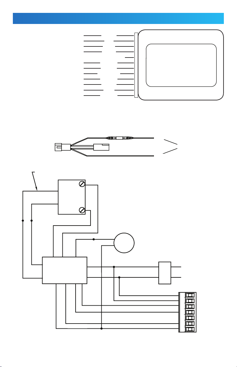
WIRING
MOTOR INPUT
MOTOR INPUT
8310-877 NO
8310-877 COM
12-24 VAC/VDC
8310-877 COM
8310-877 DATA + & ACTIVATION NO
12-24 VAC/VDC
CONTROL BOX COMMON
CONTROL BOX ACTIVE
ACTIVATION COM
MC-15
LOCK OUT RELAY
SAFETY MODULE
BLACK
BLACK
BLACK
BLACK
SAFETY
MODULE
SAFETY
SCANNER
BLUE
GREEN
TRANSFORMER
YELLOW
900/7900 SERIES
CONTROL BOX
ACTIVATION SWITCH
OR SCANNER
10
A
or
B
COM
1234567
N.O.
120 VAC24 VAC
RED
RED
RED
RED
GRAY
WHITE
ORANGE
PURPLE
RED/WHITE
BROWN
GREEN
BLUE
YELLOW
10K Resistor
to A or B
Air Solenoid
HARNESS SHOWN ABOVE
to A or B
connector on
power supply PCB
to Safety Module
BROWN
ORANGE
PURPLE
GRAY
WHITE
RED/WHITE

75.5323.01 ALLEGION SAFETY MODULE 8310-889 20180702 Page 3 of 475.5323.01 ALLEGION SAFETY MODULE 8310-889 20180702 Page 3 of 4
PROGRAMMING
1. Apply power.
RED LED = When the door is closed and someone steps into the safety zone, this indicates that it will ignore
any activation signal it receives. Therefore, the door will remain closed until the HMSS safety zone is clear.
Once the safety zone is clear and the door has been activated, a normal opening cycle will commence.
GREEN LED = If someone steps into the safety zone when the door is open, the Safety Module’s green LED
will indicate that the HMSS will be connected to the activation circuitry of the door thus holding the door open
for as long as someone is in its pattern.
2. SET LOCK-OUT TIME DELAY
The lock-out time delay for the door closing cycle must be set using the six DIP switches located on the front
of the unit. A 0 to 31 second lock-out time delay can be achieved. The lock-out time delay must be set so
that the HMSS does not send a safety signal during the closing cycle. As soon as the door reaches the jamb,
the Safety Module should reactivate the HMSS.
3. SET TIME DELAY ON SAFETY MODULE
Check to make sure that the Safety Module locks out the HMSS for the entire closing cycle of the door. If the
scanner sends a safety signal (scanner red light on) anytime during the closing cycle, the time delay set on the
Safety Module must be increased. If the door goes into safety swing as soon as it starts to close and you have
a time delay set for the length of the closing cycle, ensure that the AC power is being switched on and off at
the point of connection for the red and black wires. Correct any faults before proceeding.
4. SET DIP SWITCHES
Set the DIP switches according to the chart on page 4 to achieve the desired lock out time delay. The DIP
switches are configured to send a binary coded input to the microprocessor to establish the correct lock out
time delay.
For example:
The normal closing cycle of an automatic door lasts about 7 seconds. In order to get the proper closing lock-
out time delay needed for the closing cycle of the door, the DIP switches need to be set according to the chart
on page 4 for 7 seconds (Default Setting). To get the proper lock-out time delay DIP switches 1, 2, and 3 must
be in the ON position and DIP switches 4 thru 8 must be in the OFF position.
OFF
ON
7654321
green LED (safety beams)
red LED (lock-out time)
8
RED LED
(safety)
GREEN LED
(activation)

Page 4 of 4 75.5323.01 ALLEGION SAFETY MODULE 8310-889 20180702Page 4 of 4 75.5323.01 ALLEGION SAFETY MODULE 8310-889 20180702
Do not leave problems unresolved. If a satisfactory solution cannot be achieved after troubleshooting
a problem, please contact Allegion at 1-877-671-7011. If you must wait for the following workday to
call Allegion, leave the door inoperable until satisfactory repairs can be made. Never sacrifice the safe
operation of the automatic door or gate for an incomplete solution.
For more information, visit www.allegion.com.
The sensor manufacturer cannot be held responsible for incorrect installations or inappropriate adjustments of the sensor/device; therefore, the sensor
manufacturer does not guarantee any use of the sensor outside of its intended purpose.
The sensor manufacturer strongly recommends that installation and service technicians be AAADM-certified for pedestrian doors, IDA-certified for
doors/gates, and factory-trained for the type of door/gate system.
Installers and service personnel are responsible for executing a risk assessment following each installation/service performed, ensuring that the sensor
system installation is compliant with local, national, and international regulations, codes, and standards.
Once installation or service work is complete, a safety inspection of the door/gate shall be performed per the door/gate manufacturer recommendations
and/or per AAADM/ANSI/DASMA guidelines (where applicable) for best industry practices. Safety inspections must be performed during each service
call – examples of these safety inspections can be found on an AAADM safety information label (e.g. ANSI/DASMA 102, ANSI/DASMA 107).
Verify that all appropriate industry signage and warning labels are in place.
INSTALLATION/SERVICE COMPLIANCE EXPECTATIONS
PLEASE KEEP FOR FURTHER USE – DESIGNED FOR COLOR PRINTING
75.5323.01ALLEGIONSAFETYMODULE8310-88920180702
TIME DELAY
(sec)
DIP 1
(1 sec)
DIP 2
(2 sec)
DIP 3
(4 sec)
DIP 4
(8 sec)
DIP 5
(16 sec)
1ON OFF OFF OFF OFF
2OFF ON OFF OFF OFF
3ON ON OFF OFF OFF
4OFF OFF ON OFF OFF
5ON OFF ON OFF OFF
6OFF ON ON OFF OFF
7ON ON ON OFF OFF
8OFF OFF OFF ON OFF
9ON OFF OFF ON OFF
10 OFF ON OFF ON OFF
11 ON ON OFF ON OFF
12 OFF OFF ON ON OFF
13 ON OFF ON ON OFF
14 OFF ON ON ON OFF
15 ON ON ON ON OFF
16 OFF OFF OFF OFF ON
17 ON OFF OFF OFF ON
18 OFF ON OFF OFF ON
19 ON ON OFF OFF ON
20 OFF OFF ON OFF ON
21 ON OFF ON OFF ON
22 OFF ON ON OFF ON
23 ON ON ON OFF ON
24 OFF OFF OFF ON ON
25 ON OFF OFF ON ON
26 OFF ON OFF ON ON
27 ON ON OFF ON ON
28 OFF OFF ON ON ON
29 ON OFF ON ON ON
30 OFF ON ON ON ON
31 ON ON ON ON ON
PROGRAMMING (cont.)
Other Allegion Control Unit manuals


Popular Control Unit manuals by other brands


MikroTik
MikroTik R11e-LR2 quick start guide

Manner
Manner MES technical information

SPI Lasers
SPI Lasers redPOWER quick start guide

Frequency Central
Frequency Central Process 26 Build documentation

Frequency Central
Frequency Central Meth Amp Rev.2 Build documentation

Watts
Watts LFUSG-B-M1 installation instructions


