Allegion WRT-K User manual

75.5931.01 LOCKNETICS BR2-900 20190814 Page 1 of 6
WRT-K
1
2
12
13
3
4
11
10
9
8
5
6
7
2 RELAY LOGIC MODULE WITH BUILT-IN
900 MHZ WIRELESS TECHNOLOGY
(US version)
1 Receiver Description
1. Power input
2. Relay outputs
3. Day/Night input
4. AUX input
5. Learn buttons
6. DIP-switches
7. Potentiometers
8. Radio frequency LED (red)
9. Relay 2 LED (white)
10. Relay 1 LED (blue)
11. Tri-color signal strength LED
12. Antenna
13. 1-button transmitter
For details regarding the limited warranty:
Customer Service
1-877-671-7011 www.allegion.com/us

75.5931.01 LOCKNETICS BR2-900 20190814 Page 2 of 6
2 Precautions
Shut off all power before attempting any wiring procedures.
Maintain a clean & safe environment when.
Constantly be aware of pedestrian trafc around the door area.
Always stop pedestrian trafc through the doorway when performing tests that may result in unexpected reactions by the door.
ESD (electrostatic discharge): Circuit boards are vulnerable to damage by electrostatic discharge. Before handling any board,
ensure you dissipate your body’s ESD charge.
Always check placement of all wiring before powering up to insure moving door parts will not catch any wires and cause
damage to equipment.
Ensure compliance with all applicable safety standards and building codes upon completion of installation.
DO NOT attempt any internal repair of the components. All repairs and/or component replacements must be performed by BEA,
Inc. Unauthorized disassembly or repair may:
1. jeopardize personal safety and may expose one to the risk of electrical shock.
2. adversely affect the safe and reliable performance of the product resulting in a voided warranty.
!
CAUTION
3 Wiring
• Relays 1 and 2 are DPDT: relays 1A and 1B re simultaneously and relays 2A and 2B re simultaneously.
• Relays 1B and 2B are commonly used in applications with two (2) locking devices and/or with two (2) independent door controls.
• INPUT D/N (DAY/NIGHT mode)
- when open, allows transmitters learned in both SECURE mode and UNSECURE mode to function
- when closed, only allows transmitters learned in UNSECURE mode to function
• INPUT AUX functions regardless of learn, DIP switch, or potentiometer settings.

75.5931.01 LOCKNETICS BR2-900 20190814 Page 3 of 6
4 User Interface
DIP SWITCHES: can be set to achieve desired functionality based upon specic application requirements
LEARN BUTTONS: 900 MHz wireless transmitters can be programmed (or “learned”) as either UNSECURE or SECURE
transmitters. Any combination of up to 75 transmitters may be programmed.
DIP STATUS FUNCTION DESCRIPTION
1
STD standard
mode allows only learned/programmed transmitters to function
UNI* universal
mode allows learned/programmed and "universal transmitters" to function
2
STD standard
mode
pressing/holding or pressing/releasing transmitter activates and holds relay according to
HOLD TIME POTs (single shot)
EH extended hold pressing/holding transmitter holds relay as long as transmitter is pressed/held – once
released, relay acts according to HOLD TIME POTs
* Day/Night mode does not function when DIP-switch 1 is set to UNI.
BUTTON FUNCTION DESCRIPTION
UNSECURE unsecure transmitters learned transmitter functions when INPUT D/N is open or closed
SECURE secure transmitters learned transmitter only functions when INPUT D/N is open
POTENTIOMETERS: control output relay functionality
SIGNAL STRENGTH INDICATOR: pressing and holding transmitter button for three (3) seconds activates signal strength
LED on receiver.
POT FUNCTION DESCRIPTION
HOLD 1 relay 1 hold time 0.5 – 10 seconds
HOLD 2 relay 2 hold time 0.5 – 10 seconds
DELAY delay between relay 1 and relay 2 0 – 30 seconds
LED COLOR DESCRIPTION
GREEN strong wireless signal
YELLOW moderate wireless signal
RED weak wireless signal
75.5931.01 LOCKNETICS BR2-900 20190814 Page 4 of 6
12
12 3
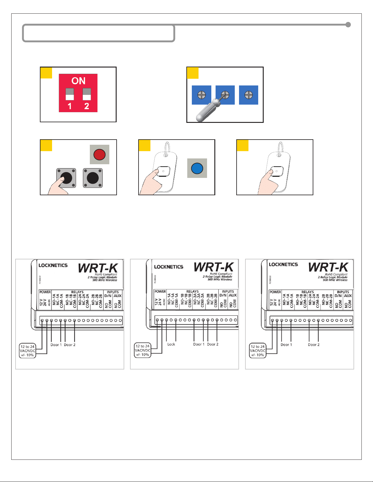
5 Setup
OPTIONAL:
TRANSMITTER PROGRAMMING
Set DIP-switches as
desired.
For DIP-switch settings,
please refer to table on
page 3.
Adjust POTs as desired.
clockwise = longer delay
counterclockwise = shorter delay
default / full CCW = no delay
See page 3 for descriptions.
see hub image on page 1
Press transmitter twice (white and
blue LEDs on receiver will illuminate).
TEST/CHECK: Press transmitter
and verify operation.
Press and release desired Secure/
Unsecure Learn button (red LED
on receiver will illuminate).
VESTIBULE CONFIGURATION: Vestibule applications may be installed and programmed so that either door 1 and door 2
open simultaneously or door 1 opens rst and door 2 opens after a delay (set by HOLD TIME potentiometers).
1-Way Trafc (simultaneous)
Door 1 and Door 2 will open simultaneously.
non-polarized non-polarized non-polarized
1-Way Trafc (lock + simultaneous)
Lock(s) will unlock and then Door 1 and
Door 2 will open simultaneously.
1-Way Trafc (sequence)
Door 1 will open and then Door 2 will open
after a delay set by DELAY POT.
R1 R2 DELAY
75.5931.01 LOCKNETICS BR2-900 20190814 Page 5 of 6
1
x2
21
1
3 V
2
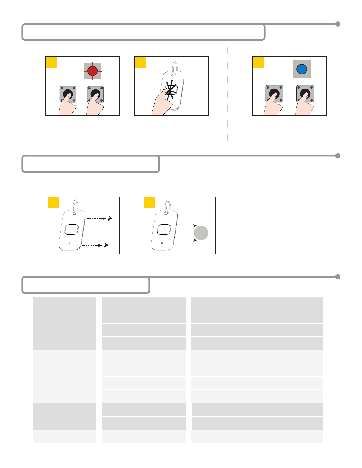
6 Removing Transmitter Programming
7 Battery Replacement
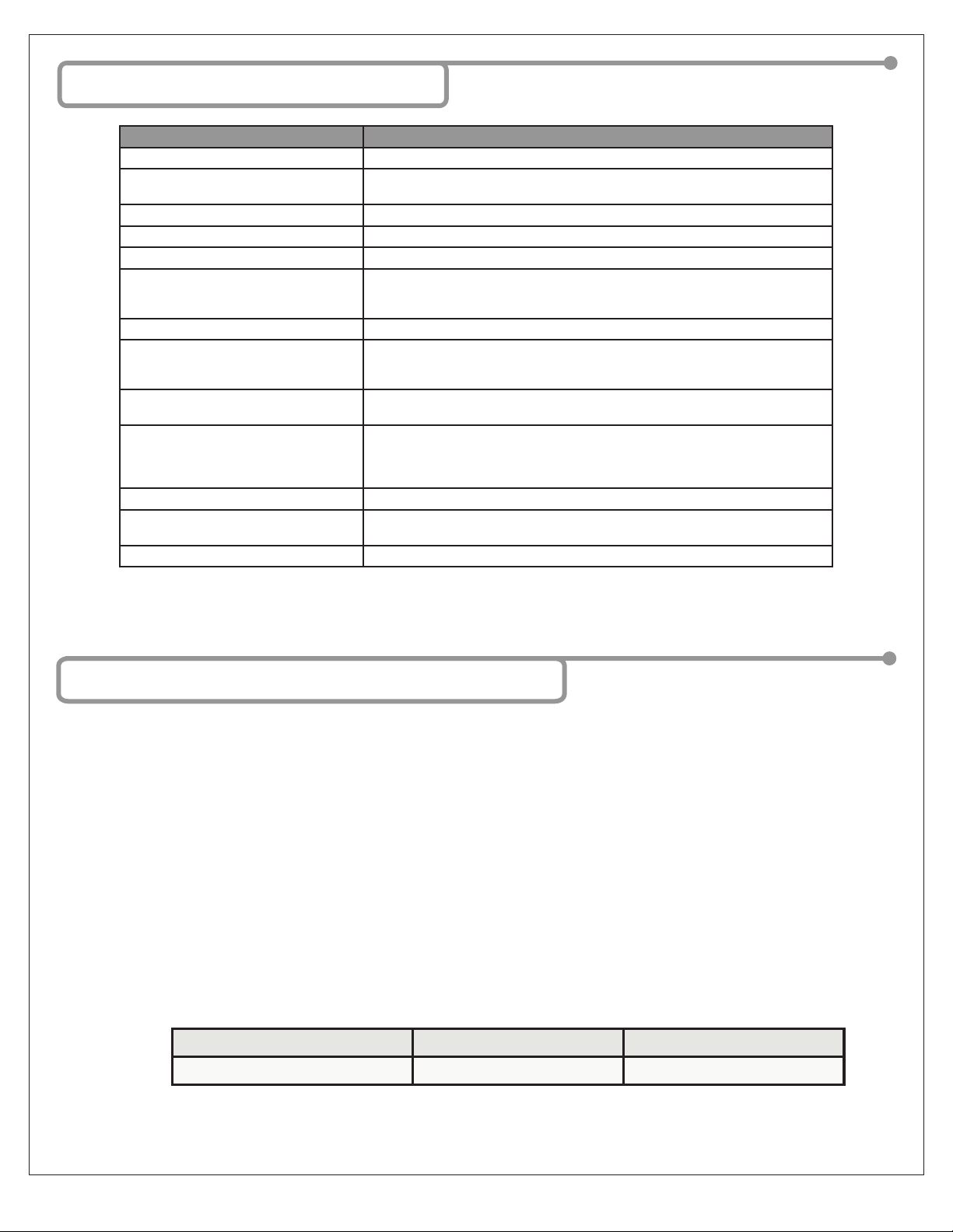
8 Troubleshooting
Press BOTH learn buttons on the
receiver until red LED ashes once
(approx. 2 seconds).
Press BOTH Learn buttons on the
receiver until blue LED illuminates
(approx. 10 seconds).
Press transmitter TWICE within
10 seconds.
Single Transmitter All Transmitters
A low-battery indicator is provided.
After transmitter button is pressed, low battery is indicated by three (3) blinks of the red, transmitter LED.
Remove back screws and disassemble. Replace 3-volt (CR2032) battery,
observing polarity, and reassemble.
Receiver will not react to
any inputs
Incorrect power Verify power supply of 12 – 24 VAC/VDC ±10% is wired to
correct terminals.
Not programmed Ensure a receiver is programmed with wireless transmitter.
Incorrect wiring Verify wiring.
Defective receiver Replace receiver.
Receiver has no output Incorrect output devices Ensure proper devices are connected to outputs.
Incorrect wiring Verify wiring.
Incorrect settings Verify programming and potentiometer settings.
Defective receiver Replace receiver.
Red LED on receiver
ickering; unable to program
Push Plate is stuck Disconnect push plates to determine which one is stuck
(LED should go out).
Faulty transmitter If LED does not go out, remove transmitter batteries to
determine which is faulty, replace transmitter.
Weak signal Antenna positioned poorly Position antenna outside of door header.
75.5931.01 LOCKNETICS BR2-900 20190814 Page 6 of 6
10 FCC / IC
“This device complies with Part 15 of the FCC Rules. Operation is subject to the following two conditions: (1) this device may not cause harmful
interference, and (2) this device must accept any interference received, including interference that may cause undesired operation.”
Changes or modications not expressly approved by product manfacturer could void the user’s authority to operate the equipment.
Note: This equipment has been tested and found to comply with the limits for a Class A digital device, pursuant to part 15 of the FCC Rules. These
limits are designed to provide reasonable protection against harmful interference when the equipment is operated in a commercial environment.
This equipment generates, uses, and can radiate radio frequency energy and, if not installed and used in accordance with the instruction manual,
may cause harmful interference to radio communications. Operation of this equipment in a residential area is likely to cause harmful interference in
which case the user will be required to correct the interference at his own expense.
This device complies with Industry Canada licence-exempt RSS standard(s). Operation is subject to the following two conditions: (1) this device
may not cause interference, and (2) this device must accept any interference, including interference that may cause undesired operation of the
device.
Le présent appareil est conforme aux CNR d’Industrie Canada applicables aux appareils radio exempts de licence. L’exploitation est autorisée aux
deux conditions suivantes : (1) l’appareil ne doit pas produire de brouillage, et (2) l’utilisateur de l’appareil doit accepter tout brouillage radioélect-
rique subi, même si le brouillage est susceptible d’en compromettre le fonctionnement.
FCC ID: 2ABWS-10BR2900 IC: 4680A-10BR2900 MODEL: 10BR2900
FCC ID: 2ABWS-10TD900HH1U IC: 4680A-10TD900HH1U MODEL: 10TD900HH1U
9 Specications
DESCRIPTION SPECIFICATION
Supply voltage: 12 – 24 VAC / VDC ±10%
Current consumption: 45 mA DC
75 mA AC
Frequency: 908 – 918 MHz (frequency hopping)
Emitted radio power: -25 dBm (TX)
Power consumption: 0.5 – 1.5 W
Transmitter capacity (per receiver):
Programmable (standard):
Universal:
75
unlimited
Temperature rating: -22 – 158 °F (-30 – 70 °C)
Input
Day / Night (24hr)
AUX
DRY contact
DRY contact
Contact rating:
Relay 1 DPDT / Relay 2 DPDT: 2 A @ 30 VDC or 2 A @ 24 VAC
LEDs: blue (relay 1 activation)
white (relay 2 activation)
red (radio frequency / learn)
tri-color (signal strength)
Certication: FCC, IC
Dimensions: 5.2” (W) x 1” (H) x 2.2” (D)
(133 mm x 25 mm x 55 mm)
Housing: ABS (white translucent)
Table of contents
Other Allegion Control Unit manuals


