manuals.online logo
Brands
  1. Home
  2. •
  3. Brands
  4. •
  5. DSC
  6. •
  7. Control Unit
  8. •
  9. DSC Downlook DLM-7 User manual

DSC Downlook DLM-7 User manual

Specifications
Power
• 11 - 14.5VDC
• Operating Current: 35mA
Video
• Up to seven 1VP-P CCIR NTSC- or PAL-compatible cameras
• Video out terminal for local video monitor with 75Wimpedence
Mounting the Panel
It is suggested that the DLM-7 Camera Selector Module and the DLM-1
Video Module be mounted in a DLC-1 Cabinet. TheDLC-1Cabinethas
been designed especially for use with Downlook components.
Before attaching the cabinet to the wall, press nylon printed circuit
boardmounting studs into the raised mounting holesfrom the back
of the cabinet. Mount the cabinet securely to the wall. It is
recommendedthatappropriatewallanchorsbeusedwhensecuring
thepaneltodrywall,plaster,concrete,brickorothersimilarsurfaces.
Remove the DLM-7 circuit board from the cardboard packaging.
Press the DLM-7 Module onto the nylon mounting studs.
Video Input Connections
The DLM-7 Module uses NTSC or PAL compatible cameras. Use
only a CCIR camera, as older types may not function properly with
the DLM-7 Module.
Install the camera mounting hardware as per the manufacturer’s
instructions and mount the camera. Connect the camera to a
monitor, and align the camera with the target area and adjust the
camera’sfocus. Ifanon-sitemonitoristobepermanentlyconnected
betweenthecameraandtheDLM-7module,themonitorconnection
must be high impedance.
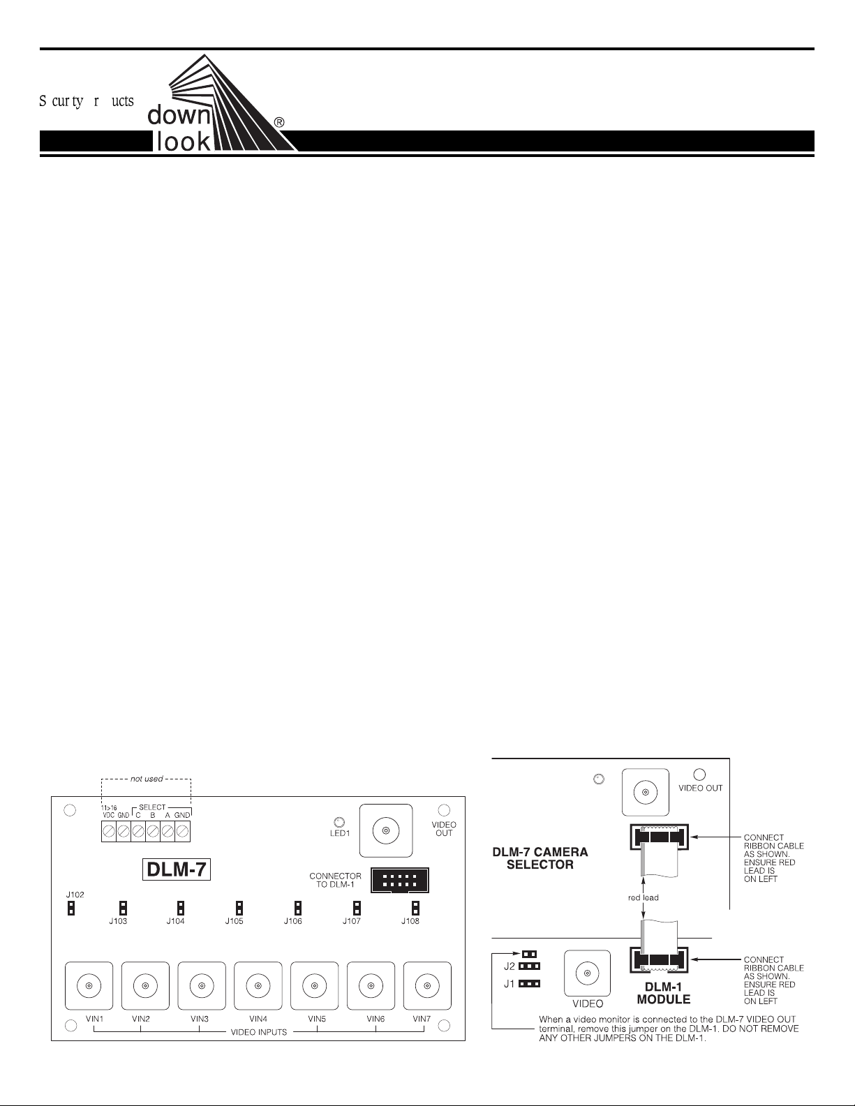
Connect the first camera to the VIN1 terminal and remove the
jumper clip from J102. If only one camera is used with the DLM-7,
it should be connected to input VIN1. Connect additional cameras
to BNC connectors VIN2 through VIN7. Up to seven cameras may
be connected to the DLM-7.
Power Requirements
The DLM-7 Camera Selector usually does not require an additional
power supply.
Connection to the DLM-1 Module
Ensure power is removed from all components before making
connections between the Downlook modules. Connect the DLM-7
ModuletotheDLM-1Module withthe10-pinribboncablesupplied.
Refer to the connection diagram below and ensure that the ribbon
cable is oriented properly.
Jumpers J102 through J108
Jumpers J102 through J108 are used to terminate unused video
inputs. If a video input is not used, short the pins for the terminal
using one of the supplied jumper clips. If a camera is connected
to a terminal, remove the clip from the jumper.
Local Video Output
A monitor may be connected to the DLM-7 to allow for local video
monitoring. The monitor will display the image from the currently
active camera. Connect a monitor with a high input impedence to
the VIDEO OUT terminal. If required, picture quality at the local
monitor may be adjusted with part R129. Use a small screwdriver
to adjust part R129; do not force the adjustment screw beyond its
natural range of motion.
System Programming
The DLM-7 itself requires no programming. Refer to the Installation
Manuals of the security system used with the Downlook system for
instructionsonprogrammingthesystemforusewithmultiplecameras.
The following restrictions apply to UL Listed applications:
1. The picture count shall not exceed 2.
2. The message/data format must be Sur-Gard 7/3.
3. Communication must be made to the listed Sur-Gard MLR2-DG
receiver with the MLRV method employed.
4. TheDLM-1andDLM-7mustbeconnectedtoonlyULListedvideo
equipment.
5. The module has been found to be compatible with the UL Listed
Sur-Gard P-16 and P-1664 units only.
DLM-7 Downlook Camera
Selector Module
INSTALLATION INSTRUCTIONS
29001204 R1
LED1
firealarmresources.com
LIMITED WARRANTY
Digital Security Controls Ltd. warrants that for a period of twelve months from the date of purchase, the product shall be free of defect in
materials and workmanship under normal use and that in fulfilment of any breach of such warranty, Digital Security Controls Ltd. shall, at its
option, repair or replace the defective equipment upon return of the equipment to its repair depot. This warranty applies only to defects in
parts and workmanship and not to damage incurred in shipping or handling, or damage due to causes beyond the control of Digital Security
Controls Ltd. such as lightning, excessive voltage, mechanical shock, water damage, or damage arising out of abuse, alteration or improper
application of the equipment.
The foregoing warranty shall apply only to the original buyer, and is and shall be in lieu of any and all other warranties, whether expressed
orimplied andof allotherobligations orliabilitiesonthepart ofDigitalSecurityControlsLtd. This warrantycontainstheentirewarranty. Digital
Security Controls Ltd. neither assumes, nor authorizes any other person purporting to act on its behalf to modify or to change this warranty,
nor to assume for it any other warranty or liability concerning this product.
In no event shall Digital Security Controls Ltd. be liable for any direct, indirect or consequential damages, loss of anticipated profits, loss of
time or any other losses incurred by the buyer in connection with the purchase, installation or operation or failure of this product.
WARNING: Digital Security Controls Ltd. recommends that the entire system be completely tested on a regular basis. However, despite
frequent testing, and due to, but not limited to, criminal tampering or electrical disruption, it is possible for this product to fail to perform
as expected.
FCC Compliance
CAUTION: Changes or modifications not expressly approved by Digital Security Controls Ltd. could void your authority to use
this equipment.
This equipment has been tested and found to comply with the limits for a Class B digital device, pursuant to Part 15 of the FCC Rules.
These limits are designed to provide reasonable protection against harmful interference in a residential installation. This equipment
generates, uses and can radiate radio frequency energy and, if not installed and used in accordance with the instructions, maycause
harmfulinterferencetoradio communications. However, there is no guarantee that interference will not occur inaparticularinstallation.
If this equipment does cause harmful interference to radio or television reception, which can be determined by turning the equipment
off and on, the user is encouraged to try to correct the interference by one or more of the following measures:
• Re-orient the receiving antenna.
• Increase the separation between the equipment and receiver.
• Connect the equipment into an outlet on a circuit different from that to which the receiver is connected.
• Consult the dealer or an experienced radio/television technician for help.
The user may find the following booklet prepared by the FCC useful: “How to Identify and Resolve Radio/Television Interference
Problems”. This booklet is available from the U.S. Government Printing Office, Washington D.C. 20402, Stock # 004-000-00345-4
© 1996 Digital Security Controls Ltd.
1645 Flint Road, Downsview, Ontario Canada M3J 2J6
Tel. (416) 665-8460 • Fax (416) 665-7498 • Tech. line (800) 387-3630 29001204 R1
firealarmresources.com

Other DSC Control Unit manuals

DSC Maxsys PC4701 User manual

DSC

DSC Maxsys PC4701 User manual

DSC PowerSeries PC585 User manual

DSC

DSC PowerSeries PC585 User manual

DSC RXL2-433 User manual

DSC

DSC RXL2-433 User manual

DSC PCL422 User manual

DSC

DSC PCL422 User manual

DSC PowerSeries Neo V1.2 User manual

DSC

DSC PowerSeries Neo V1.2 User manual

DSC MAXSYS PC4851 User manual

DSC

DSC MAXSYS PC4851 User manual

DSC PC6216 User manual

DSC

DSC PC6216 User manual

DSC PowerSeries User manual

DSC

DSC PowerSeries User manual

DSC MAXSYS  PC4850 User manual

DSC

DSC MAXSYS PC4850 User manual

DSC Maxsys PC4116 User manual

DSC

DSC Maxsys PC4116 User manual

DSC AMP-704 User manual

DSC

DSC AMP-704 User manual

DSC Misterhouse PC5401 User manual

DSC

DSC Misterhouse PC5401 User manual

DSC PC5720 User manual

DSC

DSC PC5720 User manual

DSC PC6216 User manual

DSC

DSC PC6216 User manual

DSC Misterhouse PC5401 User manual

DSC

DSC Misterhouse PC5401 User manual

DSC Power Series PC5904 User manual

DSC

DSC Power Series PC5904 User manual

DSC PC5928 User manual

DSC

DSC PC5928 User manual

DSC Power 832 User manual

DSC

DSC Power 832 User manual

DSC PowerSeries User manual

DSC

DSC PowerSeries User manual

DSC Maxsys PC4937 User manual

DSC

DSC Maxsys PC4937 User manual

DSC Sur-Gard DVACS PC54OO User manual

DSC

DSC Sur-Gard DVACS PC54OO User manual

DSC PC5200 User manual

DSC

DSC PC5200 User manual

DSC Power Series User manual

DSC

DSC Power Series User manual

DSC PC5108 User manual

DSC

DSC PC5108 User manual

Popular Control Unit manuals by other brands

Allen-Bradley FLEX I/O 1794-IV32 installation instructions

Allen-Bradley

Allen-Bradley FLEX I/O 1794-IV32 installation instructions

Belden Lumberg Automation LioN-X 0980 XSL... manual

Belden

Belden Lumberg Automation LioN-X 0980 XSL... manual

Inel ST-01RL Instructions for installation and use

Inel

Inel ST-01RL Instructions for installation and use

Wisenet SPA-D1000 quick guide

Wisenet

Wisenet SPA-D1000 quick guide

GEM 507 Installation, Operating and Maintenance Instructions for the Installer and the User

GEM

GEM 507 Installation, Operating and Maintenance Instructions for the Installer and the User

Intellitec Battery Guard 1000 installation guide

Intellitec

Intellitec Battery Guard 1000 installation guide

SANDIA aerospace MARC-70 Simplifying Complex Installations

SANDIA aerospace

SANDIA aerospace MARC-70 Simplifying Complex Installations

Vimar LINEA 30506 manual

Vimar

Vimar LINEA 30506 manual

molex SST-PB3S-CLX-RLL Series User reference guide

molex

molex SST-PB3S-CLX-RLL Series User reference guide

Pignology Piglet quick start

Pignology

Pignology Piglet quick start

Armstrong Delta2 FLY Series Installation and operation manual

Armstrong

Armstrong Delta2 FLY Series Installation and operation manual

Pickering SYSTEM 10 user manual

Pickering

Pickering SYSTEM 10 user manual

Enerpac V-161 instruction sheet

Enerpac

Enerpac V-161 instruction sheet

Ensemble Designs Avenue 5820 Data Pack

Ensemble Designs

Ensemble Designs Avenue 5820 Data Pack

Supermicro MicroBlade 6119M-T2N user manual

Supermicro

Supermicro MicroBlade 6119M-T2N user manual

Fluidmaster 402CARHR installation instructions

Fluidmaster

Fluidmaster 402CARHR installation instructions

GW Instek GDB-03 user manual

GW Instek

GW Instek GDB-03 user manual

Advantech PCM-261 Startup manual

Advantech

Advantech PCM-261 Startup manual

manuals.online logo
manuals.online logoBrands
  • About & Mission
  • Contact us
  • Privacy Policy
  • Terms and Conditions

Copyright 2025 Manuals.Online. All Rights Reserved.