7
NAE1045320 / 11.2011
2. Function
2.1 Features
For use in level 1 and 2 AC electric vehicle charging systems
Detects both AC (0...500 Hz) and DC ground faults
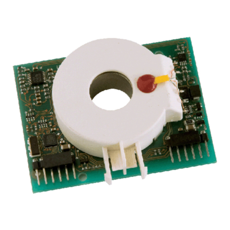
Internal measuring current transformer with test winding and screening for electrical interfer-
ence field reduction, inside diameter 15 mm
Measuring range 0...20 mA, with analog voltage output
Switching signal at the output according to the requirements of UL 2231-2, type CCID20
Simple mounting of the module by snap-in locking mechanism at the current transformer
Monitoring of the connection to the measuring current transformer
Reset via control input X10
2.2 Description
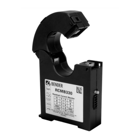
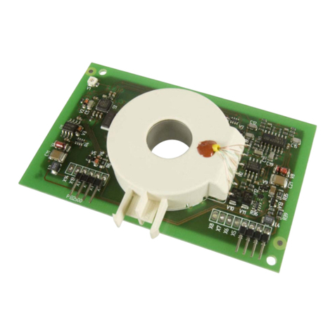
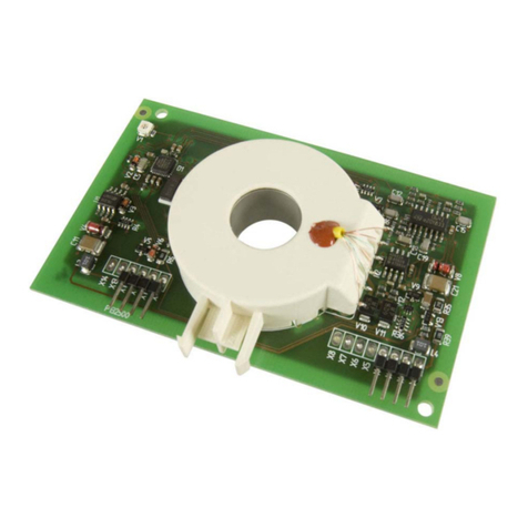
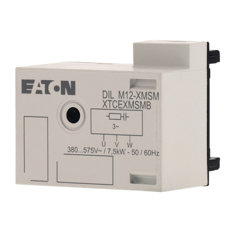
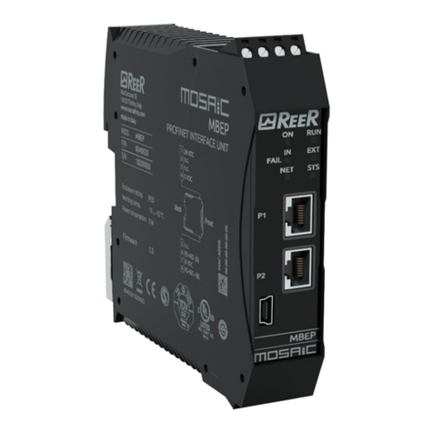
The RCMB101 is a ground fault current module (CCID20) for monitoring AC/DC ground faults in elec-
tric vehicle charging stations. The CCID20 shall be mounted into the charging station as an open-
type circuit board. The electrical connection is made with circuit board plug connectors.
The AC/DC sensitive ground fault current module RCMB101 (alternate term CCID20) is suitable for
monitoring in electric vehicle charging stations where direct and/or alternating fault currents are
likely to occur with a value that is constantly greater than zero. This also applies to the detection of
leakage currents. The CCID20 is to be mounted into the charging stations as an open-type circuit
board. The electrical connection is established by means of circuit board plug connectors.
2.3 Function
The module detects the zero sequence current caused by leakage and fault currents in the conduc-
tors passed through the built-in current transformer. The module measures both AC and DC cur-
rents. The final value is calculated as an RMS value. A signal in proportion to the RMS value is made
available across the output X1. A second output marked X12 provides a switching signal when val-
ues are outside the permissible measuring range or in case of high or soaring ground fault currents.
2.3.1 Self test after connection to the supply voltage
Once the supply voltage has been switched on, the module carries out a two-stage self-test. In a first
sequence, a current flow of 11mA, 400Hz is applied to the test winding for one second. Then a direct
current of 22mA is applied, also for one second.
The resulting measured value of typical 1.2V of the first 11 mA test phase is available at the analog
output X1. The digital output X12 does not switch.
The 22 mA test phase causes the digital output X12 to switch after max. 800ms and makes an analog
output voltage of 4.85V available at X1.
The automatic start of calibration also causes the digital output X12 to switch.


