manuals.online logo
Brands
  1. Home
  2. •
  3. Brands
  4. •
  5. Bpt
  6. •
  7. Control Unit
  8. •
  9. Bpt GVV/200 US User manual

Bpt GVV/200 US User manual

CENTRALITA DE CONTROL
GVV/200
Permite el funcionamiento de los
módulos manos libres NC/220,
XC/220 y NC/221, XC/221 en instala-
ciones de audiointercomunicacion y de
videointercomunicacion de la serie 200.
Su tarea principal consiste en deter-
minar la dirección de la comunica-
ción y en reducir automáticamente
el volumen del canal opuesto.
GVV/200 MAIN CONTROL UNIT
Enables the twin-channel receivers
NC/220, XC/220 and NC/221,
XC/221 to be operated in series-200
audio- and video entry installations.
Its main function consists in determi-
ning the direction of communication
and automatically reducing the volu-
me of the opposite channel.
To permit the balancing circuit to
work properly, the volume controls in
the entry panels must be set, the
MR/100 remote microphone instal-
led in TM-series entry panels, and
the microphone in Targha-series
entry panels moved to the remote
position.
Adjustment of the audio volume
controls.
Targha-series entry panels: both
half way.
TM-series entry panels: the one
towards the receivers almost at the
minimum setting, and the one
towards the entry panel at the desi-
red volume.
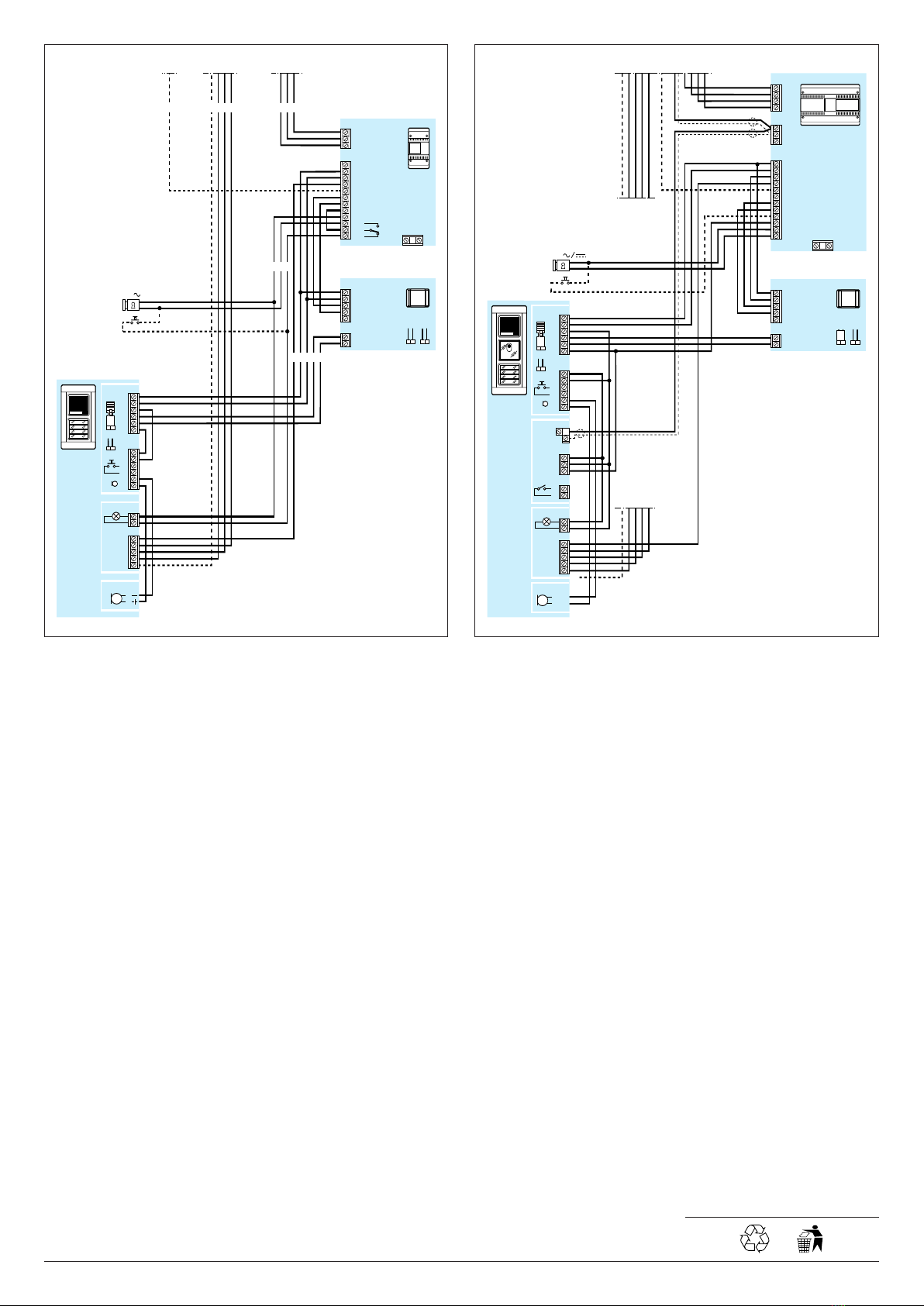
The switchboard comes with two
jumpers, SW1 and SW2,which
should be positioned depending on
the type of user extension and
power supplier used in the installa-
tion (fig. 1):
SW1 OFF - SW2 OFF in installations
with NC/220, XC/220 and A/200;
SW1 ON - SW2 OFF in installations
with NC/221, XC/221 and VA/200;
SW1 ON - SW2 ON in installations
with NC/221, XC/221 and A/200
with GS/200.
Function of each terminal (fig. 1)
IN terminal board
11 audio from entry panel
12 audio to entry panel
OUT terminal board
5–power supply
21 +
11 audio to receiver
12 audio from receiver
Mmute (1)
(1) In the event loud noises in the
area around the entry panel make
automatic switching difficult, the
audio channel from the entrypanel
1
SW1
11
12
OUT
11
21
5
IN
12
M
ONOFF
SW2
1
GVV/200 US
EINSTRUCCIONES
PARA LA INSTALACION
02.2009/2405-9112
1
2
3
can be disabled by connecting the
terminal M(mute) to earth using the
auxiliary button of the twin-channel
receiver.
Technical features
• Supply voltage: 12 VDC.
•Current demand: max. 50 mA.
• Working temperature range: from
0°C to +35 °C.
• Dimensions: 60x44x16mm (fig. 2).
The unit can be installed on a DIN
guide (EN 50022) (fig. 3).
DISPOSAL
Do not litter the environment with
packing material: make sure it is dis-
posed of according to the regula-
tions in force in the country where
the product is used.
When the equipment reaches the
end of its life cycle, take measures to
ensureit is not discarded in the envi-
ronment.
The equipment must be disposed of
in compliance with the regulations in
force, recycling its component parts
wherever possible.
Components that qualify as recy-
clable waste feature the relevant
symbol and the material’sabbrevia-
tion.
60 mm
44 mm
16 mm
2
BPT S.p.A.
Via Cornia, 1
33079 Sesto al Reghena-PN-Italy
[email protected] – www.bpt.it
NOTE: This equipment has been tested and found to com-
ply with the limits for a Class B digital device, pursuant to Part
15 of the FCC Rules. These limits are designed to provide
reasonable protection against harmful interference in a residential instal-
lation.
This equipment generates, uses and can radiate radio frequency energy
and, if not installed and used in accordance with the instructions, may
cause harmful interference to radio communications. However, there is
no guarantee that interference will not occur in a particular installation.
If this equipment does cause harmful interference to radio or television
reception, which can be determined by turning the equipment off and
on, the user is encouraged to try to correct the interference by one or
more of the following measures:
- Reorient or relocate the receiving antenna.
-Increase the separation between the equipment and receiver.
-Connect the equipment into an outlet on a circuit different from that to
which the receiver is connected.
-Consult the dealer or an experienced radio/TV technician for help.
EN INSTALLATION
INSTRUCTIONS
LEVITON
LEVITON S de RL de CV
LAGO TANA 43 Col HUICHAPAN CP
11290
MEXICO DF Tel 5082 1040
LEA Y CONSERVE ESTE
INSTRUCTIVO
2
Para un funcionamiento correcto del
circuito de balance, en las placas
externas es preciso regular los
potenciómetros del volumen, insta-
lar el micrófono remoto MR/100 en
las placas externas de la serie TM y
desplazar el micrófono en posición
remota en las placas externas de la
serie Targha.
Ajuste de los potenciómetros del
volumen audio.
Placas externas serie Targha:
ambos a media carrera.
Placas externas serie TM: aquél
hacia los derivados internos casi al
mÌnimo y aquél hacia la placa exter-
na al volumen deseado.
La centralita dispone de dos puen-
tes SW1 ySW2 acolocar según el
tipo de derivado interno y de alimen-
tador empleado en la instalación (fig.
1):
SW1 OFF - SW2 OFF en instalacio-
nes con NC/220, XC/220 y A/200;
SW1 ON - SW2 OFF en instalacio-
nes con NC/221, XC/221 y VA/200;
SW1 ON - SW2 ON en instalacio-
nes con NC/221, XC/221 y A/200
con GS/200.
Función de los bornes (fig. 1)
Bornera IN
11 audio desde la placa externa
12 audio hacia la placa externa
Bornera OUT
5–
alimentación
21 +
11 audio hacia el derivado interno
12 audio desde el derivado interno
Mmute (1)
(1) En el caso de que fuertes ruidos,
presentes en la zona alrededor de la
placa externa, dificulten la conmuta-
ción automática, es posible excluir el
canal audio procedente de la placa
externa conectando a masa el borne
M(mute) mediante el pulsador auxi-
liar del módulo manos libes.
Características técnicas
•Alimentación: 12 VDC.
• Consumo: 50 mA máx.
•Temperatura de operación: entre
0°C y +35 °C.
NOTA: este equipo ha sido ensayado y declarado conforme
alos límites establecidos para un dispositivo digital de Clase
B, de acuerdo con el Apartado 15 de las Normas FCC. Estos límites
han sido diseñados para ofrecer una protección razonable contra
interferencias perjudiciales en una instalación residencial.
Este equipo genera, utiliza y puede emitir energía de radiofrecuencia y,
si no se instala y utiliza conforme a las instrucciones, puede crear
interferencias perjudiciales para las radiocomunicaciones. Sin embar-
go, no se garantiza que no se produzcan interferencias en una insta-
lación concreta.
Si este equipo crea interferencias perjudiciales para la recepción de
radio o televisión, lo cual se puede comprobar apagando y encen-
diendo el equipo, se recomienda al usuario que intente corregir la
interferencia adoptando una o varias de las siguientes medidas:
-Modifique la orientación o la posición de la antena receptora.
-Aumente la distancia que separa el equipo del receptor.
-Conecte el equipo a un tomacorriente de un circuito diferente de
aquel al que está conectado el receptor.
-Solicite la asistencia de su distribuidor o de un técnico de radio/TV
cualificado.
• Dimensiones: 60x44x16 mm (fig.
2).
Es posible instalar el aparato en guía
DIN (EN 50022) (fig. 3).
ELIMINACION
Comprobar que no se tire al me-
dioambiente el material de emba-
laje, sino que sea eliminado con-
forme a las normas vigentes en el
país donde se utilice el producto.
Al final del ciclo de vida del aparato
evítese que éste sea tirado al
medioambiente.
La eliminación del aparato debe
efectuarse conforme a las normas
vigentes y privilegiando el reciclaje
de sus partes componentes.
En los componentes, para los
cuales está prevista la eliminación
con reciclaje, se indican el símbolo y
la sigla del material.
3
Max. 3
CP
C: 1 mm2
C: 0,5 mm2
A:1mm2
B:0,5 mm2
150 m 100 m
CP: Personal door-bell button.
Pulsador de llamada desde el rellano.
AE: Auxiliary door-lock release button.
Pulsador auxiliar abrepuerta.
WIRE CROSS-SECTION
SECCION DE LOS CONDUCTORES
8A
CP
CP
985
HA/200
5
21
8
11
12
14
HPC/1+
HA/200+
…KHPS+
…HPP/6
…HTS
B
C
A/200N
+B
5
21
8
8A
11
12
23
5
8
9
16
NO
C
NC
AE
12V
NC/220
A
B
3
1
BB B C
AA A
GVV/200
21
11
12
M
5
OUT
IN
11
12
B B BB B
NC/220
B
SW1
4
B
1
2
3
4
5
7
8
9
5
7
8
9
SW2
XC/220
5
7
8
9
2
CP
B
LN
4
SE 7503.2UL
SINGLE OR MULTI-FLAT AUDIO
ENTRY INSTALLATION WITH
NOVA, EXEDRA HANDS-FREE
RECEIVERS AND TARGHA ENTRY
PANEL.
EQUIPO DE AUDIOINTERCOMUNI-
CACION MONO O MULTIFAMILIAR
CON DERIVADOS INTERNOS
MANOS LIBRES NOVA, EXEDRA Y
PLACA EXTERNA TARGHA.
5
1
NC/221
8A985
HA/200
5
21
8
11
12
14
HPC/1+
HA/200+
…KHPS+
…HPP/6
…HTS
B
C
A/200N
+B
5
21
8
8A
11
12
23
5
8
9
16
NO
C
NC
AE
12V
A
AA A
GVV/200
21
11
12
M
5
OUT
IN
11
12
B B BB B
4
1
2
3
4
SW1 SW2
GS/200
5
21
C
11
8
RS
CP
3
CP
5
7
8
9
E
20
XC/221
2
CP
5
7
8
9
20
B
B
BB B CB
B
YC/201
C
5
7
8
9
20
E
XC/200+SC/200
SC/200 C
5
7
8
9
20
E
5
7
8
9
CP
SC/200
C/200+SC/200
C
5
7
8
9
20
E
5
7
8
9
CP
LN
SE 7504.2UL
MULTI-FLAT MIXED AUDIO ENTRY
INSTALLATION WITH HANDSETS
AND NOVA, EXEDRA HANDS-FREE
RECEIVERS AND TARGHA ENTRY
PANEL.
EQUIPO DE AUDIOINTERCOMUNI-
CACION MULTIFAMILIAR MIXTO
CON DERIVADOS INTERNOS CON
AURICULAR Y MANOS LIBRES
NOVA, EXEDRA Y PLACA EXTERNA
TARGHA.
6
A
B
D
C
VA/200
AE
12V
3
4
7
5
6
8
9
HAVC/200
5
6
11
12
14
HPV/1+
HAVC/200+
HTS
GVV/200
21
11
12
M
5
OUT
IN
11
12
SW1
TC
V−
V+
VS
NVM/200+NC/221
CP
5
6
21
8
8A
22
11
12
23
14
13
16
3
4
5
6
7
8
9
E
5
7
8
9
E
20
SW1 SW2
XVC/200+XKP/200+
XC/221+XKP/85
CP
3
4
5
6
7
8
9
20
E
XC/221
CNH
C
LN
75
75
SE 8041.2UL
SINGLE HOUSE VIDEO ENTRY
INSTALLATION WITH NOVA, EXE-
DRA HANDS-FREE MONITOR AND
TARGHA ENTRY PANEL.
EQUIPO DE VIDEOINTERCOMUNI-
CACION MONOFAMILIAR CON
MONITOR MANOS LIBRES NOVA,
EXEDRA Y PLACA EXTERNA TAR-
GHA.
A
B
D
VA/200
5
6
8
9
GVV/200
21
11
12
M
5
OUT
IN
11
12
5
6
21
8
8A
22
11
12
23
14
13
16
AE
12V
NVM/200+NC/221
HAVC/200
5
6
11
12
14
HPV/1+
HAVC/200+
…KHPS+
…HPP/6+
…HTS
SW1
TC
V−
V+
VS
C
VDV/400
3
4
3
4
3
4
4
3
1
2
3
4
5
6
75
3
4
7
34
45689
8A
4321
123
4
1
3
4
5
6
7
8
9
E
75
SW1
1
2
3
4
n
n
n
n
SW2
C
XC/221
3
XV/200+XKP/200+
XC/221+XKP/85
3
4
5
6
7
8
9
20
E
CNH
75
CP
CP
5
7
8
9
E
20
75
CP
2
YKP/200+YV
M1
M2
7A
3
4
5
6
7
8
9
10
11
12
18
19
20
75
CP
YVM/200
3
4
5
6
7
8
9
10
11
18
20
75
XV/200+XKP/200+
XC/200+XKP/85
CP
3
4
5
6
7
8
9
20
E
CXC/200
CN/2
VM/200+VKP/203
3
4
5
6
7
8
9
10
11
12
13
14
15
16
17
18
19
20
CP
75
LN
7
SE 8042.3UL
MULTI-FLAT MIXED VIDEO ENTRY
INSTALLATION WITH MONITORS
WITH HANDSET, NOVA, EXEDRA
HANDS-FREE MONITORS AND
TARGHA ENTRY PANEL.
EQUIPO DE VIDEOINTERCOMUNI-
CACION MULTIFAMILIAR MIXTO
CON MONITORES CON AURICULAR,
MONITORES MANOS LIBRES NOVA,
EXEDRA Y PLACA EXTERNA TAR-
GHA.
8
Fig. 5 - Connection diagram bet-
ween VA/200 power supplier,
GVV/200 main control unit and TM
entry panel.
Fig. 5 - Esquema de conexión entre
el alimentador VA/200, centralita de
control GVV/200 y la placa exterior
TM.
A
B
D
VA/200
5
6
8
9
GVV/200
21
11
12
M
5
OUT
IN
11
12
5
6
21
8
8A
22
11
12
23
14
13
16
C
3
4
7
34
n56898A3
123
n
A
A
D
E
D
E
MVTC/100
MC/…
TTS/...+
TMP/...+
MVA/100.
01
+
MVTC/100+
MC/...+
MR/100
AE
12V
1
234n
n
MVA/100.
01
MR/100
42
1
4
5
6
14
5
6
17
19
-
+
5
6
8
11
12
14
SW1
SW3
SW2
C
1
2
3
4
-
+
SW2
LN
5
Fig. 4 - Connection diagram bet-
ween A/200R power supplier,
GVV/200 main control unit and TM.
Fig. 4 - Esquema de conexión entre
el alimentador A/200R, centralita de
control GVV/200 y la placa exterior
TM.
43
8A 985
B
C
A/200N
+B
5
21
8
8A
11
12
23
5
8
9
16
NO
C
NC
AE
12V
A
BB C
GVV/200
21
11
12
M
5
OUT
IN
11
12
B
SW1
MVA/100.01
D
E
MC/..
MR/100
TTS/...+
TMP/...+
MVA/100.01+
MC/...+
MR/100
SW3
SW2
21
BBB
B
B B BB B
A A
5
6
8
11
12
14
5
6
17
19
-
+
C
1
2
3
4
A
SW2
LN
4

Other Bpt Control Unit manuals

Bpt VLS/3 User manual

Bpt

Bpt VLS/3 User manual

Bpt TA/P1 User manual

Bpt

Bpt TA/P1 User manual

Bpt HAV/200 US User manual

Bpt

Bpt HAV/200 US User manual

Bpt DMVC/01 User manual

Bpt

Bpt DMVC/01 User manual

Bpt DPS User manual

Bpt

Bpt DPS User manual

Popular Control Unit manuals by other brands

IBASE Technology ET875 Series user manual

IBASE Technology

IBASE Technology ET875 Series user manual

Flexball 4500 CPP manual

Flexball

Flexball 4500 CPP manual

Toray TORAYFIL HFUG-2020AN instruction manual

Toray

Toray TORAYFIL HFUG-2020AN instruction manual

RAK RAK4260 quick start guide

RAK

RAK RAK4260 quick start guide

Beninca KER manual

Beninca

Beninca KER manual

Fibocom H330S Hardware user manual

Fibocom

Fibocom H330S Hardware user manual

Silicon Laboratories MGM13S02 user guide

Silicon Laboratories

Silicon Laboratories MGM13S02 user guide

Biamp Qt X300 manual

Biamp

Biamp Qt X300 manual

Gira System 3000 operating instructions

Gira

Gira System 3000 operating instructions

Tews Technologies TPMC500-SW-42 user manual

Tews Technologies

Tews Technologies TPMC500-SW-42 user manual

Yale SLE 3 Operation manual

Yale

Yale SLE 3 Operation manual

JAMO ATM 50 user manual

JAMO

JAMO ATM 50 user manual

YASKAWA MP2000 Series user manual

YASKAWA

YASKAWA MP2000 Series user manual

Alcad 9650007 MDA-300 instructions

Alcad

Alcad 9650007 MDA-300 instructions

Alpha Outback Energy Cordex 24-400W manual

Alpha Outback Energy

Alpha Outback Energy Cordex 24-400W manual

Grundfos CU 241 Installation and operating instructions

Grundfos

Grundfos CU 241 Installation and operating instructions

Pentair AUTOTROL 368 user guide

Pentair

Pentair AUTOTROL 368 user guide

Mitsubishi Electric MELSEC iQ-R60DA4 Startup User's Manual

Mitsubishi Electric

Mitsubishi Electric MELSEC iQ-R60DA4 Startup User's Manual

manuals.online logo
manuals.online logoBrands
  • About & Mission
  • Contact us
  • Privacy Policy
  • Terms and Conditions

Copyright 2025 Manuals.Online. All Rights Reserved.