manuals.online logo
Brands
  1. Home
  2. •
  3. Brands
  4. •
  5. VIA Technologies
  6. •
  7. Control Unit
  8. •
  9. VIA Technologies 40 User manual

VIA Technologies 40 User manual

Valvoindustria Ing. Rizzio S.p.A.
Globe valves
1
MV0100000.27-0 (Ver. 200603a)
Via Circonvallazione, 10
13018 Valduggia (VC), Italy
Tel: +39 0163 47891
Fax: +39 0163 47895
www.vironline.com
Gate valves
Istruzioni per l’uso delle valvole a saracinesca e a globo VIR
(Installazione, Impiego Manutenzione)
How to use the VIR gate and globe valves
(Installation, Operating and Maintenance Instructions)
INFORMAZIONI GENERALI
GENERAL INFORMATION
Le valvole a saracinesca e a globo VIR sono prodotte in una gran varietà di
rating e connessioni. Il portafoglio VIR include modelli adatti all’utilizzo su
impianti di irrigazione, di riscaldamento/condizionamento e alla distribuzione
del vapore. Informazioni specifiche sulle pressioni di esercizio e sui fluidi
utilizzabili (secondo la classificazione dalla “Pressure Equipment Directive” -
Dir. 2014/68/UE) con ciascun modello sono fornite nel prossimo paragrafo,
che definisce anche i modelli coperti da queste istruzioni.
Fare riferimento alle schede tecniche VIR specifiche per ciascuna valvola
per ulteriori informazioni.
VIR gate and globe valves are produced in a wide range of ratings and connections. VIR portfolio
includes models suitable for irrigation, HVAC systems and steam distribution. Specific information
on pressures and fluids that can be used (as defined by the Pressure Equipment Directive - Dir.
2014/68/UE) with each valve are provided in the next paragraph, which also indicates for which
models this manual is applicable.
See VIR valve specific technical sheets for further information.
2
CAMPO DI UTILIZZO PRESSIONE/TEMPERTURA
PRESSURE AND TEMPERATURE RATINGS
Modello
Model
Pressione nell’intervallo di temperatura
Non-shock pressure at temperature range
Applicazione
Application
Categoria PED
PED category
40
Acqua:
16
bar da 0°C a 8
0
°C
Water: 16bar from 0°C to 80°C
Liquidi, gruppo 2
Liquids, group SEP ( )
56
Acqua:
20
bar da 0°C a
100
°C
, max 13bar a 150°C
Water: 0bar from 0°C to 100°C, max 13bar at 150°C
Liqu
idi, gruppo 2
Liquids, group SEP ( )
90, 90LK
Acqua: 16bar da 0°C a 100°C, max 7bar a 170°C
Water: 16bar from 0°C to 100°C, max 7bar at 170°C
Liquidi, gruppo 2
Liquids, group SEP ( )
100, 100LK
Acqua: 20bar da 0°C a 100°C, max 10bar a 170°C
Water: 0bar from 0°C to 100°C, max 10bar at 170°C
Liquidi, gruppo 2
Liquids, group SEP ( )
110
Acqua: 25bar da
-
10°C ( ) a 100°C, max 13bar a 170°C
Water: 5bar from -10°C (*) to 100°C, max 13bar at 170°C
Liquidi, gruppo 2
Liquids, group SEP ( )
120
Acqu
a: 25bar da
-
10°C ( ) a 100°C, max 13bar a 170°C
Water: 5bar from -10°C (*) to 100°C, max 13bar at 170°C
Liquidi, gruppo 2
Liquids, group SEP ( )
914
Acqua: 16bar da 0°C a 100°C
Water: 16bar from 0°C to 100°C
Liquidi, gruppo 2
Liquids, group
DN≤300: SEP ( )
DN≥350: Cat. I
924
Acqua: 16bar da 0°C a 110°C
Water: 16bar from 0°C to 110°C
Liquidi, gruppo 2
Liquids, group
DN≤300: SEP ( )
DN≥350: Cat. I
1510 Acqua: 16bar da -10°C ( ) a 120°C, fino a 300°C secondo scheda tec.
Water: 16bar from -10°C (*) to 1 0°C, up to 300°C acc. tech sheet
Liquidi, gr. 1 e 2
Gas, group 1 & 2
Liquids, gr. 1 e
Gases, gr. 1 &
DN≤25: SEP ( )
DN≥32: Cat. I
1520
Acqua: 16bar da
-
10°C ( ) a 110°C
Water: 16bar from -10°C (*) to 110°C
Liquidi, gruppo 2
Liquids, group SEP ( )
400, 405
Acqua: 16bar da 0°C a 100°C, 7,9bar oltre e fino a 170°C
Water: 16bar from 0°C to 100°C, 7,9bar above and up to 170°C
Liquidi, gruppo 2
Liquids, group SEP ( )
(*) = temperature sotto zero solo per acqua additivata con liquidi antigelo.
Only for below zero water temperatures where antifreeze fluids have been added.
(**) = "Sound Engineering Practice", esente marcatura CE (Art. 4.3 Dir. 2014/68/UE)
"Sound Engineering Practice", free of CE marking (Art. 4.3 Dir. 2014/68/EU)
I campi di lavoro precedenti si intendono per condizioni di utilizzo regolari: colpi di ariete, urti,
carichi di fatica, ambienti esterni corrosivi o erosivi e trasporto di fluidi con proprietà abrasive
devono essere evitati.
Si prega di verificare l’applicabilità di queste istruzioni a modelli qui non indicati contattando VIR.
The operative conditions shown above are intended for non-shock operating conditions: water
hammer, impacts, stress loads, corrosive or erosive external environmental elements and the
transport of fluids with abrasive properties should be avoided.
Please verify applicability off these instructions to models not specifically indicated in the table by
contacting VIR.
3
ISTRUZIONI DI MONTAGGIO
MOUNTING INSTRUCTIONS
Prima di procedere all’installazione assicurarsi che la valvola sia adatta alle pressioni, alle
temperature, ai fluidi di servizio ed all’ambiente in cui sarà installata. L’impianto deve garantire
adeguati punti di drenaggio e sfiato, prevenire effetti dannosi quali formazione di sedimenti,
cavitazione, corrosione e/o reazioni chimiche incontrollate ed un’agevole esecuzione di pulizia,
ispezione periodica e manutenzione, ove necessario.
Le valvole VIR sono state progettate per i carichi di un impianto efficiente e perfettamente calibrato;
sollecitazioni anomale, quali quelle dovute ad un’incorretta installazione e/o messa a punto
dell’impianto, al traffico, al vento, ai terremoti, non sono state considerate nel dimensionamento.
E’ responsabilità dell’installatore e/o del progettista assicurarsi che l’applicazione non ecceda i limiti
di pressione e temperatura della valvola e che l’installazione sia realizzata a regola d’arte in
accordo con le vigenti normative e regolamentazioni locali.
Le valvole a saracinesca e a globo VIR incluse nella tabella al paragrafo precedente possono
essere installate in qualunque posizione (verticale, orizzontale, inclinata), si suggerisce tuttavia
l’installazione in orizzontale con il volantino verso l’alto. Le valvole a saracinesca sono bidirezionali
ed il flusso può attraversarle in entrambe le direzioni, le valvole a cuneo inclinato Fig. 1520 e globo
Fig. 1510, Fig. 400 e Fig. 405 sono invece monodirezionali e la freccia sul corpo indica la direzione
obbligatoria del flusso. La posizione scelta per l’installazione deve garantire l’accessibilità alla
valvola per le operazioni di manovra, ispezione, manutenzione.
Evitare che materiale utilizzato nella connessione dei tubi o bave presenti sui terminali dei tubi
stessi ostruiscano parte del passaggio (si raccomanda il lavaggio della linea prima della messa in
esercizio o a seguito di eventuali lavori di manutenzione).
Installare le valvole in modo da non sottoporle a sforzi di flessione, taglio o trazione/compressione
da parte della linea. Prevedere l’utilizzo di supporti per tubi in numero sufficiente, allineati con cura
e posti a una distanza idonea per le dimensioni e il tipo di tubo da sostenere. In ogni caso, fare
attenzione a non sollecitare la valvola con carichi anomali (quindi non previsti in fase di progetto)
dovuti a un insufficiente o incorretto posizionamento dei supporti.
Before proceeding with the installation, please ensure the valve is suitable for the pressures,
temperatures, operating fluids and environment in which it will be installed. A correct installation
must ensure adequate drainage and venting of the circuit, the prevention of harmful effects such as
sediment deposits, cavitation, corrosion and/or uncontrolled chemical reactions; it must also ensure
easy cleaning and easy periodic inspection and maintenance of the system, if necessary.
VIR valves are designed for loads of an efficient and perfectly calibrated plant; abnormal stresses,
such as those due to an incorrect installation and/or fine tuning of the system, to traffic, wind,
earthquake, were not considered in the design.
It is the responsibility of the installer and/or of the plant designer to ensure that the application does
not exceed the limits of pressure and temperature of the valve and is carried out in accordance with
local current laws and regulations.
VIR gate and globe valves referred to in the table of previous paragraph can be installed in any
position (vertical, horizontal, inclined), we suggest however to install them horizontally with
handwheel pointing upward. Gate valves can be used with flow going in both directions, while for
Fig. 1520 gate valves with oblique disc and Fig. 1510, Fig. 400 and Fig. 405 globe valves flow must
match the direction of the arrow marked on their body. The position chosen for the installation
should allow for accessibility to the valve during operation, inspection and maintenance.
Please avoid that any material used to connect the pipes or that any burrs present on the pipe ends
themselves protrude inside the bore and obstruct part of the flow (it’s advisable to flush the line
before its start or after eventual maintenance on the system).
The valves should be installed in such a way so that the pipeline does not subject the valve to any
torsion, bending or tension. We recommend the use of pipe brackets. Those must be in adequate
numbers, carefully aligned and placed at a distance suitable to the size and type of the pipe that
has to be supported. In any case, be careful not to overload the valve with any unexpected
additional stresses, not considered in the design stage, due to unsatisfactory numbers or incorrect
positioning of the brackets.

4
Connessioni filettate
Threaded Connections
Le valvole vanno installate sui tubi utilizzando, dove necessario, sigillanti idonei per l’applicazione e
il tipo di fluido. Il filetto sul tubo deve essere corrispondente a quello realizzato sulla valvola ed in
conformità ai requisiti di norma applicabili (fare riferimento alla scheda tecnica della valvola). Tale
filetto deve inoltre essere privo di abrasioni, ammaccature o distorsioni che potrebbero
pregiudicare il corretto accoppiamento (e quindi anche la tenuta verso l’esterno) con la
connessione sulla valvola.
Installare le valvole in posizione di chiusura per evitare sollecitazioni anomale sul corpo (con
possibilità di torsione delle superfici di tenuta e successivo trafilamento di fluido) durante
l’installazione. Per lo stesso motivo afferrare l’esagono/ottagono di presa con la pinza/chiave in
corrispondenza dell’estremità filettata che si sta avvitando sul tubo, mai l’estremità opposta o la
giunzione stessa. Prestare attenzione a non serrare il tubo ad una distanza eccessiva dalla zona
filettata, per non indurre extra momenti flettenti sulla valvola.
Per i tubi filettati maschio prestare infine attenzione a non avvitare il tubo troppo in profondità nella
valvola con il rischio di deformare le sedi di tenuta e di successive perdite durante l’esercizio.
The valves shall be installed on pipes using, if necessary, a sealant suitable for the application and
the expected type of fluid. The pipe threading shall be suitable to the valve threading and in
accordance to the applicable standard requirements (please refer to the valve technical sheet). The
pipe threading shall also be free of abrasions, bruises or sprains that could impair the correct
coupling with the valve and, in consequence, the outwards seal.
The valves shall be installed in close position to avoid additional stresses on the body (with
possible twisting of the sealing surfaces resulting in possible leakages). For the same reason the
pipe clamp or the key wrench must always grasp onto the hexagon/octagon portion of the threaded
end that needs to be screwed to the pipe. Never grasp the other end or the junction itself. Be
careful not to tighten the pipe at an excessive distance from the threaded area, in order not to
induce additional bending moments on the valve.
Lastly, please avoid to screw male threaded pipes too far into the valve. This could result in a
damage of the valve seats with resulting leakages once the valve is operational.
5
Connessioni flangiate
Flanged Connections
Utilizzare flange corrispondenti a quelle presenti sulla valvola ed in conformità ai requisiti di norma
applicabili (fare riferimento alla scheda tecnica della valvola). Le flange devono già essere presenti
sulle tubazioni e non devono essere saldate dopo che la valvola è stata installata.
Per garantire la tenuta predisporre una adeguata guarnizione tra le flange (la scelta e il montaggio
di tale guarnizione è a cura dell’installatore).
Sull’impianto deve essere stato già predisposto uno spazio pari allo scartamento della valvola. Non
utilizzare i bulloni per avvicinare le tubazioni. Serrare i bulloni in croce.
The flanges on the pipes should correspond to those on the valve and should be in accordance to
the applicable standard requirements (please refer to the valve technical sheet). Flanges should
already be available on the pipes and should not be welded once the valve has been installed.
To guarantee tightness, a gasket must be placed between each couple of flanges. It’s up to the
Installer to choose and mount a proper gasket.
A proper place with the same length as the valve must be available on the pipeline. Do not use
bolts to bring the pipes closer. Clamping bolts must be cross tightened.
USO E MANUTENZIONE
USE AND MAINTENANCE
Le valvole devono essere manovrate periodicamente (almeno 1 volta al mese), eseguendo un ciclo
completo di apertura e chiusura.
Le valvole a saracinesca e a globo VIR non necessitano di alcuna ulteriore manutenzione che
richieda la manomissione o lo smontaggio del dispositivo; le giunzioni sono sigillate ed i dispositivi
di tenuta non sono raggiungibili senza lo smontaggio completo della valvola.
Per i soli modelli VIR Fig. 90, Fig. 90LK, Fig. 100, Fig. 100LK e Fig.120 il gruppo vitone può essere
smontato per ispezione/manutenzione. L’operazione va effettuata in sicurezza, utilizzando
dispositivi di protezione idonei. Evacuare completamente la linea accertandosi che non sia più
sotto pressione prima di eseguire qualsiasi operazione. Nel caso di interventi di manutenzione su
più valvole, ciascun vitone va tassativamente rimontato sul proprio corpo di provenienza.
La presenza di perdite e/o danni esterni alla struttura della valvola comporta la necessità della
completa sostituzione della stessa. Per i soli modelli dotati di premistoppa eventuali perdite
dallo stelo potrebbero essere arrestate serrando il premistoppa in senso orario. Registrare il
premistoppa evitando l’utilizzo di leve e serrandolo quanto basta per arrestare la perdita (avendo
comunque cura di non danneggiare la valvola con l’applicazione di forza eccessiva). Tale manovra
va eseguita solo indossando idonei dispositivi di protezione. Se la perdita non dovesse arrestarsi
potrebbe essere comunque necessario sostituire la valvola.
Le valvole (escluse Fig. 1510, Fig. 1520, Fig. 400 e Fig. 405) devono essere utilizzate
esclusivamente come valvole d’intercettazione, sono quindi utilizzabili solo in posizione
completamente aperta o completamente chiusa, devono inoltre essere manovrate esclusivamente
mediante il volantino (o chiave per Fig. 90LK e Fig. 100LK) fornito da VIR, senza ausilio di ulteriori
dispositivi di manovra.
VIR declina ogni responsabilità diretta o indiretta nel caso di improprio utilizzo, manomissione,
modifica o smontaggio delle valvole. L’improprio utilizzo, la manomissione e/o modifica, comporta il
decadimento della garanzia e di eventuali Certificazioni applicabili alla valvola.
Ai fini della rintracciabilità del prodotto, su alcuni modelli il numero di lotto di realizzazione (batch
number) è indicato in apposita etichetta applicata sull’imballo dell’articolo (valvole in ottone e
bronzo) o su targhetta applicata al corpo (valvole in ghisa).
6
The valves need to be operated on a regular basis of (at least once per month) with an open/close
cycle. VIR gate and globe valves do not need any additional maintenance requiring disassembly
and/or tampering of the device; the joints are sealed and sealing devices are unreachable without
complete disassembly of the valve.
For VIR Fig. 90, Fig. 90LK, Fig.100, Fig. 100LK and Fig. 120 models only bonnet can be
disassembled for inspection/maintenance. Before taking any action verify the line is no longer
under pressure, wearing of proper protection gear is mandatory for this maneuver. When
performing maintenance on more than one valve, each bonnet must be remounted to its
original body.
Valves must be replaced in case of leakages and/or damages to their structure. Only for models
with adjustable packing, leakages through the stem may be stopped by tightening the packing
nut. Rotate the nut clockwise just enough to stop the leakage (and taking care not to damage the
valve with excessive strength). Wear proper protection gear before executing this maneuver. If
leakage doesn’t stop, the valve may have to be replaced anyway.
The valves (Fig. 1510, Fig. 1520, Fig. 400 and Fig. 405 excluded) have been designed and
manufactured to be exclusively used as shut-off valves, therefore they shall be used in the fully
open or fully closed position only. They must be operated only by acting on the handwheel (or key
for Fig. 90LK and Fig. 100LK) provided by VIR without any other additional device.
VIR declines any direct or indirect responsibility in case of improper use, tampering, modification or
dismantling of the valves. The improper use, tampering and/or modification, makes void any
warranty or Certification applicable to the valve.
For product traceability purposes, on some models the manufacturing batch number is indicated in
a dedicated label onto the valve box (brass and bronze items) or on a tag attached to the body
(cast and ductile iron items).
SMALTIMENTO
DISPOSAL
Alla fine della loro vita operativa le valvole potranno essere rimosse dall’impianto, seguendo una
procedura adeguata alla loro tipologia e condizioni di esercizio. Proteggere le aperture delle valvole
rimosse così da prevenire la dispersione nell’ambiente e/o il contatto con eventuali materiali
inquinanti o pericolosi rimasti al loro interno.
Smaltire quindi le valvole conformemente ai requisiti delle vigenti normative ambientali, di salute e
di sicurezza. In assenza di normative e/o regolamenti specifici cogenti e inerenti al luogo
dell’installazione VIR consiglia:
- di recuperare i componenti metallici come materia prima;
- di avviare a smaltimento dedicato le guarnizioni e/o gli elementi di tenuta (PTFE, NBR, EPDM,
FKM, etc.) in quanto soggetti a possibile contaminazione da parte dei fluidi intercettati e/o da
prodotti di lubrificazione;
- di conferire i materiali di imballaggio che accompagnano il prodotto all’eventuale sistema di
raccolta differenziata presente sul territorio.
At the end of their life cycle it will be possible to remove the valves from the system, following a
procedure adequate to the type and conditions of the system. Once un-mounted, protect the ends
of the valves to avoid any contact or leaks into the environment of eventual polluting or dangerous
residues which may be trapped inside.
Dispose of the valves according to the current environmental, health and safety regulations in force
in the place of the installation. If no specific regulations apply in the region, VIR recommends:
- to recycle the metal parts as raw material;
- to dispose of the seals and/or sealing elements (PTFE, NBR, EPDM, FKM, etc.) through
specialized companies, as they may have been contaminated by fluids and/or lubricants while in
use;
- to dispose of the packing elements through the separate collection system available in the place
of installation.

This manual suits for next models

12

Other VIA Technologies Control Unit manuals

VIA Technologies COMe-8X91 User manual

VIA Technologies

VIA Technologies COMe-8X91 User manual

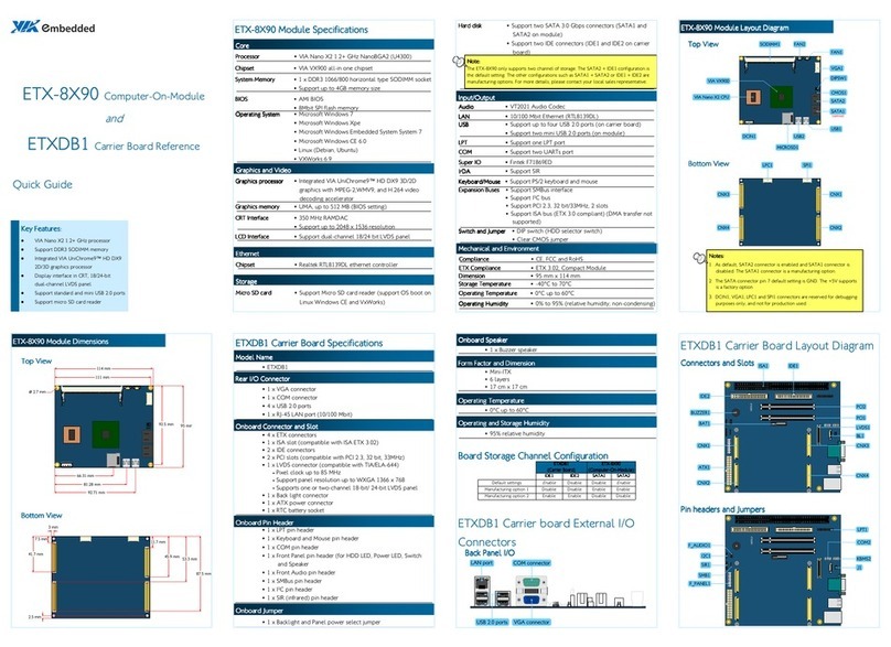
VIA Technologies ETX-8X90 User manual

VIA Technologies

VIA Technologies ETX-8X90 User manual

VIA Technologies SOM-9X35 Guide

VIA Technologies

VIA Technologies SOM-9X35 Guide

VIA Technologies VNT6656GUV00 User manual

VIA Technologies

VIA Technologies VNT6656GUV00 User manual

VIA Technologies WMP-G10 User manual

VIA Technologies

VIA Technologies WMP-G10 User manual

VIA Technologies VNT9271BB05B User manual

VIA Technologies

VIA Technologies VNT9271BB05B User manual

VIA Technologies VAB-600-B User manual

VIA Technologies

VIA Technologies VAB-600-B User manual

VIA Technologies QSM-8Q60 User manual

VIA Technologies

VIA Technologies QSM-8Q60 User manual

VIA Technologies QSM-8Q60 User manual

VIA Technologies

VIA Technologies QSM-8Q60 User manual

VIA Technologies ETX-8X90 User manual

VIA Technologies

VIA Technologies ETX-8X90 User manual

VIA Technologies VAB-3000 User manual

VIA Technologies

VIA Technologies VAB-3000 User manual

VIA Technologies SOM-3000-STK User manual

VIA Technologies

VIA Technologies SOM-3000-STK User manual

VIA Technologies VAB-600-C User manual

VIA Technologies

VIA Technologies VAB-600-C User manual

VIA Technologies VNT6656G6A10 User manual

VIA Technologies

VIA Technologies VNT6656G6A10 User manual

VIA Technologies VX800 Series Owner's manual

VIA Technologies

VIA Technologies VX800 Series Owner's manual

VIA Technologies SOM-9X35-STK User manual

VIA Technologies

VIA Technologies SOM-9X35-STK User manual

VIA Technologies SOM-6X80 User manual

VIA Technologies

VIA Technologies SOM-6X80 User manual

Popular Control Unit manuals by other brands

Sentiotec CK 31 Instructions for installation and use

Sentiotec

Sentiotec CK 31 Instructions for installation and use

Smartgen CMM365A-2G user manual

Smartgen

Smartgen CMM365A-2G user manual

ESA CC-10 instruction manual

ESA

ESA CC-10 instruction manual

Bola E 680-21 operating instructions

Bola

Bola E 680-21 operating instructions

LEGRAND 0 676 97 manual

LEGRAND

LEGRAND 0 676 97 manual

Kaysun KCCT-64 IPS Installation and operation instructions

Kaysun

Kaysun KCCT-64 IPS Installation and operation instructions

ABB NMBA-01 Installation and startup guide

ABB

ABB NMBA-01 Installation and startup guide

Pilz PNOZ mi1p product manual

Pilz

Pilz PNOZ mi1p product manual

Longsung U9507A user manual

Longsung

Longsung U9507A user manual

Ebyte E51 Series user manual

Ebyte

Ebyte E51 Series user manual

Digi XBee user manual

Digi

Digi XBee user manual

AXIOMTEK CEM501 Quick installation guide

AXIOMTEK

AXIOMTEK CEM501 Quick installation guide

ADTRAN Total Access 300 Series manual

ADTRAN

ADTRAN Total Access 300 Series manual

Bailey Infi 90 IMHSS02 Instruction

Bailey

Bailey Infi 90 IMHSS02 Instruction

Toa AT-063Ap instruction manual

Toa

Toa AT-063Ap instruction manual

Keysight VXI Bus 75000 C Series User and programming manual

Keysight

Keysight VXI Bus 75000 C Series User and programming manual

Telit Wireless Solutions M.2 N930 Series Hardware user's guide

Telit Wireless Solutions

Telit Wireless Solutions M.2 N930 Series Hardware user's guide

Mircom BBX-2000 Mechanical installation

Mircom

Mircom BBX-2000 Mechanical installation

manuals.online logo
manuals.online logoBrands
  • About & Mission
  • Contact us
  • Privacy Policy
  • Terms and Conditions

Copyright 2025 Manuals.Online. All Rights Reserved.