3. Connect the other end of the earthing cable to the earthing point.
7 Commissioning
WARNING!
Risk of injury due to unexpected movement of components.
• Protect the positioning range from unwanted intervention.
• Keep foreign objects out of the positioning range.
Input Description
0 Extend stop
1 Retract stop
Tab. 3
Output 1 Output 2 LED Open
(yellow)
LED Closed
(yellow)
Description
0 1
Off Lights up
Stop is extended
1 0
Lights up Off
Stop is retracted
Tab. 4
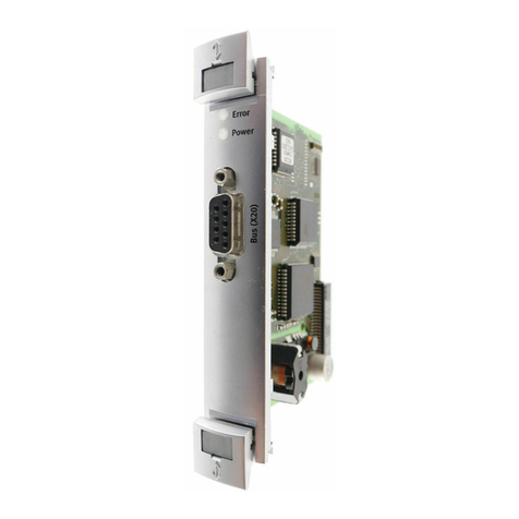
1. Switch on the supply voltage.
ÄThe "Power" LED lights up green. Depending on the position of the stop,
the LED "Open" or LED "Closed" lights up yellow.
2. Extend stop by creating a 0-signal at the input of the port1 è Tab. 2.
ÄThe LED "Closed" lights up yellow.
The switching status at output 1 of the port 2 is a 0-signal.
The switching status at output 2 of the port 2 is a 1-signal.
3. Travel with transported material into the stop position.
ÄThe stop is pushed into the stop position.
The LED "Closed" continues to light up yellow.
4. Retract stop by creating a 1-signal at the input of the port1.
ÄThe transported material is released. The LED "Open" lights up yellow.
The switching status at output 1 of the port 2 is a 1-signal.
The switching status at output 2 of the port 2 is a 0-signal.
5. Execute a test run. In doing so, check whether the stop moves through the
intended positioning cycle completely. If necessary, correct the cushioning
setting.
After a successful test run, the stopper cylinder is ready for operation.
Cushioning setting
6Cushioning setting
Fig. 8
• Turn screw for cushioning setting6:
– Clockwise (+) = increase in cushioning force
– Anti-clockwise (–) = decrease in cushioning force
ÄThe stop should reach the end position safely. Observe the maximum
load to be stopped dependent on the transport speed
è 12 Technical data.
8 Operation
WARNING!
Risk of injury from touching hot surfaces.
Contact with housing can cause burn injuries. This can frighten people and cause
them to act in an unpredictable manner. This can lead to other forms of secondary
damage.
• Avoid unconscious touching of the housing.
• Inform operating and maintenance staff about the possible hazards.
• Before maintenance work: Let the drive cool down to room temperature.
WARNING!
Risk of injury due to unexpected movement of components.
• Protect the positioning range from unwanted intervention.
• Keep foreign objects out of the positioning range.
9 Cleaning
• Clean the outside of the product with a soft cloth. Do not use aggressive
cleaning agents.
10 Malfunctions
10.1 Diagnostics
LED Meaning
Power lights up green Actuator supply voltage at the port 1 pin4is
24VDC±15%è Tab. 2.
Power flashes green
(4Hz)
Actuator supply voltage at the port 1 pin4 is outside the val-
id range.
Power off Power supply is switched off.
– Power flashes
green (1Hz)
– Open /Closed off
The stop has not reached the end position.
Note: The stopper cylinder conducts 3 attempts to reach the
end position. After that, the LED display occurs.
Tab. 5
10.2 Fault clearance
Fault description Cause Remedy
Tensions Install the product so it is free
of tension; maintain evenness
of the bearing surface
è 5 Installation.
Stop does not move.
Wear Send product to Festo for
repair.
No power supply Check the supply voltage.
Lateral force is too high. Reduce load.
Stop does not retract.
Lateral force is too high. Select a larger stopper cylinder.
Cushioning setting too high. Reduce cushioning force on the
cushioning setting 6
è 7 Commissioning.
Transported material load too
low.
Increase load.
Stop does not travel into the
stop position.
Dirt in the range of motion of
the stop.
Clean range of motion of the
stop.
Cushioning setting too low. Increase cushioning force on
the cushioning setting 6
è 7 Commissioning.
Conveyor speed too high. Reduce speed
Stop travels hard into the stop
position.
Cushioning performance too
low.
Select a larger stopper cylinder.
Transported material is above
the stop.
Transported material continues
to travel.
Stop does not extend.
No power supply. Check the supply voltage.
Tab. 6
10.3 Repair
Send product to the Festo repair service for repair.
11 Recycling
ENVIRONMENT!
Dispose of the packaging and product according to the valid provisions of envir-
onmentally sound recycling èwww.festo.com/sp.


